
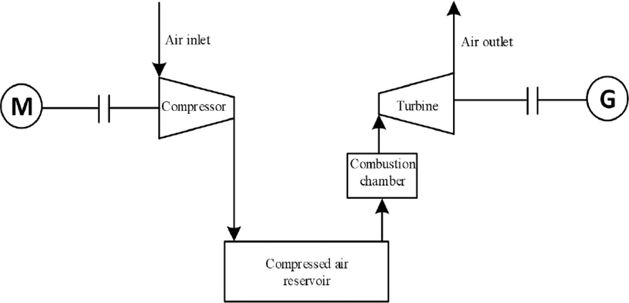
Figure 1
The scheme of basic CAES installation
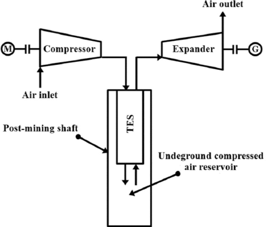
Figure 2
The scheme of adiabatic CGES system
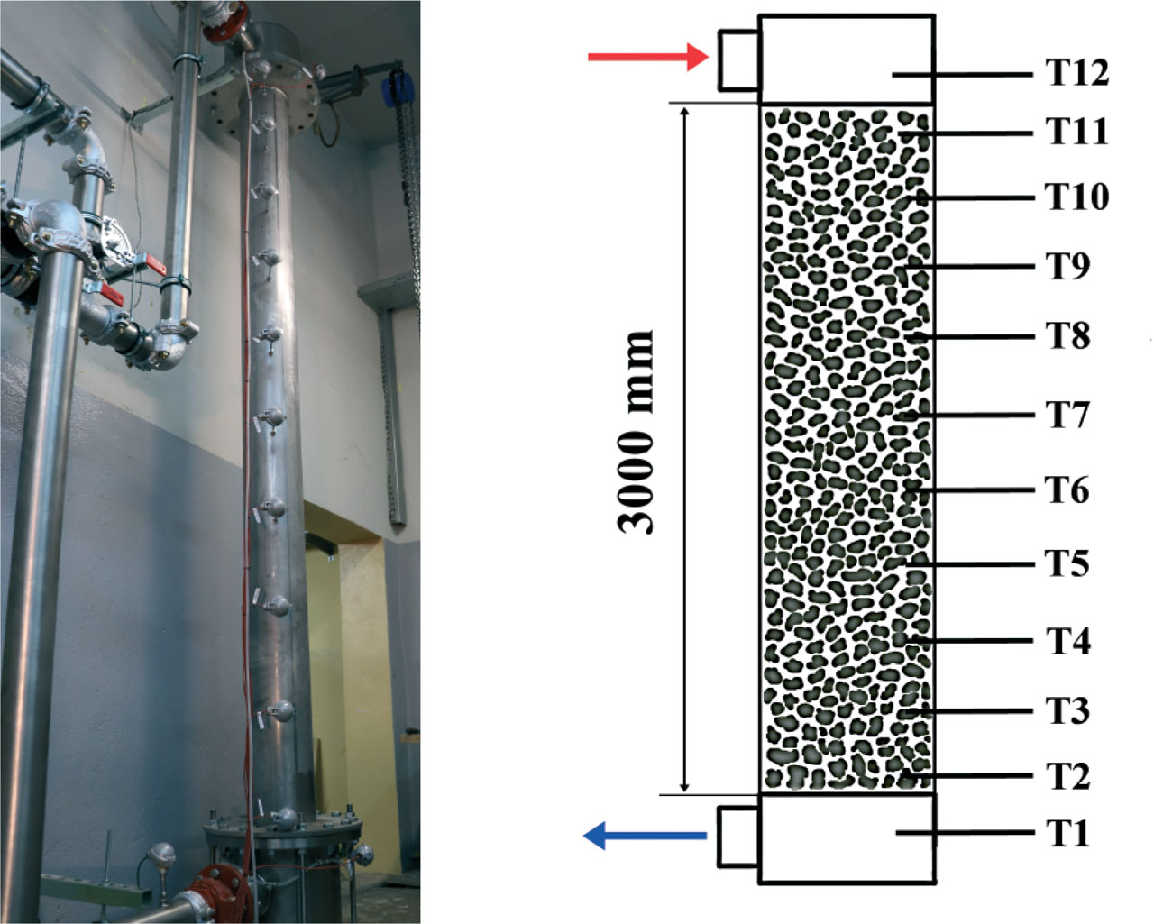
Figure 3
The laboratory bench of TES installation
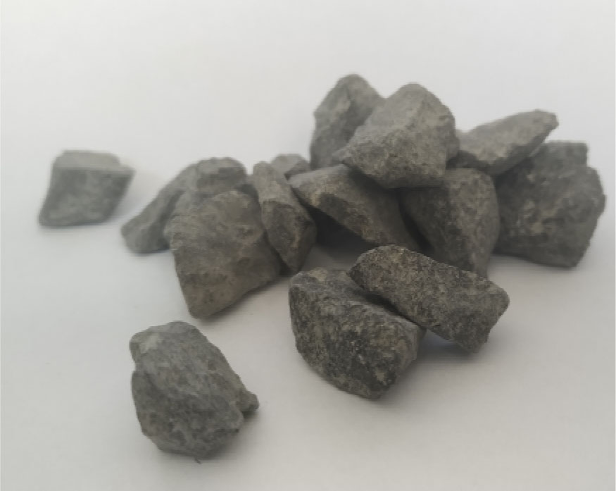
Figure 4
The studied basalt samples
Table 1
The obtained and assumed parameters of the investigated materials in TES installation
| Item | Basalt | Granite | Ceramics – alumina | Unit |
|---|---|---|---|---|
| Density | 2660 | 2400 | 3960 | kg/m3 |
| Heat capacity | 870–922 | 810–840 | 766–962 | J/kg · K |
| Thermal conductivity | 2.1–2.3 | 1.9–2.1 | 24.5–32.8 | W/m · K |
| Max. operating temperature | ~700 | 650 | 1600 | °C |
Table 2
The studied values of particle diameters and porosity for analyzed samples of materials in TES installation
| Item | No. 1 | No. 2 | No. 3 | No. 4 | Unit |
|---|---|---|---|---|---|
| Particle diameter Dp | 24.5 | 20 | 15.5 | 12 | mm |
| Porosity ɛ | 0.39 | 0.385 | 0.38 | 0.375 | - |
Table 3
The boundary conditions for the rock deposit in TES installation
| Item | Value | Unit |
|---|---|---|
| Inlet air temperature | 80 | °C |
| Inlet air mass flow | 0.04 | kg/s |
| Ambient temperature | 20.1 | °C |
| Ambient pressure | 101325 | Pa |
| Average external heat transfer coefficient | 5 | W/m2K |
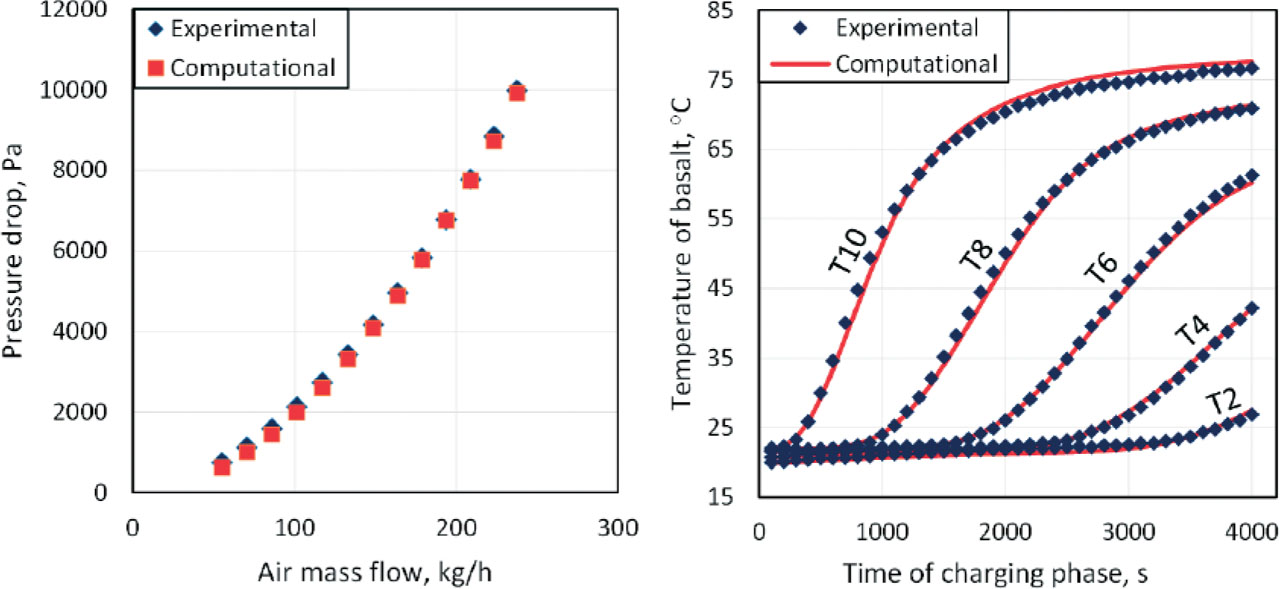
Figure 5
Example comparison of air pressure drop (left) and basalt temperature (right) functions
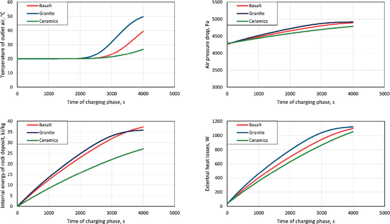
Figure 6
Characteristic of temperature of outlet air, air pressure drop, internal energy of rock deposit and external heat losses as a time functions for the investigated materials in TES installation
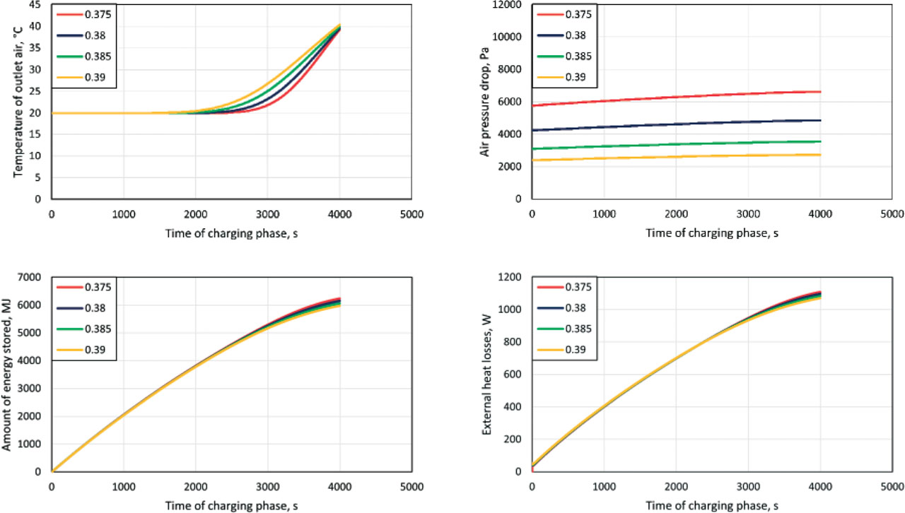
Figure 7
Characteristic of outlet air temperature, air pressure drop amount of energy stored and external heat losses as a time functions during the charging phase for different porosity value of basalt-filled reservoir in TES installation