

Introduction
Global climate change has intensified the need for scientists and engineers to design and construct environmentally friendly, sustainable coastal structures. In the coming decades, littoral areas are expected to face increasingly severe challenges, including higher design waves, unexpected overtopping, and greater risks of coastal flooding due to structural damage (Chen et al., 2025; Cunha et al., 2025; Gazi et al., 2025; Yuan et al., 2025). Breakwaters play a crucial role in coastal protection by mitigating the impact of wave action, thereby reducing the risk of flooding and coastal erosion. Their primary function is to dissipate wave energy, alleviate currents, and facilitate sediment deposition, which promotes beach formation and shoreline stability (Du et al., 2025; Fotopoulos et al., 2025; Yuksel et al., 2025).
Various types of breakwaters are widely employed in coastal engineering, such as detached and attached breakwaters or caisson-type structures constructed using materials, including concrete blocks, rock, and steel. Traditionally, the primary layer of breakwaters has been constructed using large natural stones to resist wave forces effectively. However, the availability of natural stones of suitable size and quality is becoming increasingly limited in many coastal regions because of resource depletion and environmental restrictions on quarrying activities. This scarcity has driven a shift toward mass concrete armored units that can be fabricated in controlled shapes, such as tetrapods, dolos, and tribars, tailored for optimal interlocking and wave energy dissipation. These engineered concrete units have become a popular and practical alternative in modern breakwater construction, offering consistent performance and adaptability to diverse design requirements (Anastasaki et al., 2016; Sukcharoen et al., 2024; Gísladóttir et al., 2025; Wijesekara et al., 2025).
However, the widespread use of concrete in breakwater construction has raised significant sustainability concerns. Concrete, which is the most widely used construction material, exemplifies this dilemma. Figure 1 illustrates several types of concrete armor units commonly employed for coastal protection. Among these, the earliest and most recognized is the tetrapod, which was developed in 1950 by Pierre Danel and Paul Anglès d'Auriac at the Laboratoire Dauphinois d'Hydraulique (now Artelia) in Grenoble, France. The tetrapod is a purpose-designed concrete block for wave energy dissipation, specifically engineered to resist coastal erosion in structures such as breakwaters and seawalls (Kim & Suh, 2013; Park et al., 2014; Mitsui et al., 2023). Its unique interlocking geometry enhances the stability by effectively dissipating wave forces and minimizing the displacement of individual units. This innovative design represents a significant advancement in coastal engineering and has since been widely adopted worldwide for shoreline protection.
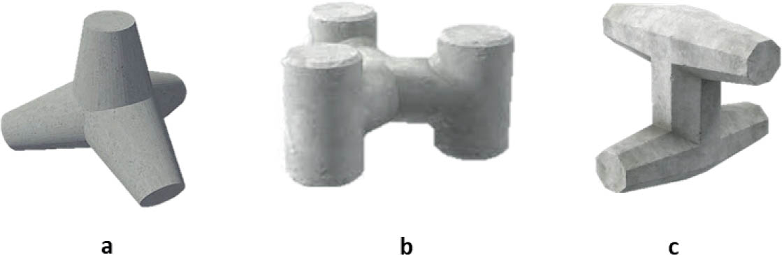
FIGURE 1.
Concrete armor units commonly used in rubble mound breakwaters: (a) tetrapod, (b) tribar, and (c) dolos
Source: own work.
While its mechanical versatility and the global abundance of its feedstocks underlie its prevalence, the manufacture of its binding agent, portland cement, is responsible for approximately 8% of worldwide CO2 emissions (Ishak & Hashim, 2015; Lehne & Preston, 2018; El-Gamal et al., 2023; Keintjem et al., 2024). As vital infrastructure, breakwaters protect coastlines, harbors, and marine installations from the prolonged forces of wave action, thereby maintaining regional structural stability and supporting the ecological balance. Given the high cost, substantial material consumption, and long-term durability challenges associated with traditional breakwater construction, it is essential to explore innovative and sustainable design solutions. In particular, optimizing armor unit shapes and breakwater slopes to improve material efficiency and reduce embodied carbon represents a promising pathway toward more sustainable coastal infrastructure.
Armor erosion caused by wave attacks is recognized as one of the primary failure modes in the design of mound breakwaters. Consequently, the hydraulic stability of the armor layer has been the subject of extensive research in recent decades. Hanzawa et al. (2012) investigated the stability of concrete armor blocks subjected to solitary wave conditions through hydraulic model experiments on breakwaters composed of wave-dissipating units. Similarly, Maruyama et al. (2014) and Mitsui et al. (2016) conducted hydraulic model tests and numerical analyses to examine the stability of armor units positioned behind composite breakwaters under overflowing tsunami waves. Safari et al. (2018) analyzed the hydraulic stability of Starbloc armor units and evaluated their influence on overtopping performance. Mares-Nasarre et al. (2022) performed physical model tests to assess the stability of cube-armored mound breakwaters in depth-limited breaking wave conditions, demonstrating that their observed stability was lower than predictions based on existing empirical formulas. Aiming to enhance breakwater stability while reducing construction costs and material usage, Yuksel et al. (2022) explored the performance of high-density cubes in the armor layers. These studies represent only a few examples of experimental and numerical investigations conducted to characterize the hydraulic behavior of armor units used in breakwater design.
Although numerous studies have examined the hydraulic stability of armor units under various wave conditions, most have focused on individual armor shapes or single slope configurations, with limited comparative assessments across multiple armor types and slopes. Furthermore, the integration of embodied carbon analysis into breakwater design has been largely overlooked, despite its growing importance for sustainable infrastructure. Therefore, this study aims to investigate the design efficiency of breakwaters constructed with different types of concrete armor units, quantifying the required material volumes and associated embodied carbon to identify optimal configurations that balance hydraulic stability, material efficiency, and environmental impact.
Methodology
This study investigates the design efficiency of breakwaters constructed with three concrete armor unit types – tetrapods, tribars, and dolos – across three slope configurations: 1 : 1.5, 1 : 2, and 1 : 3. The methodology involves determining the required armor unit weight and quantity for each slope–armor combination using empirical stability equations, calculating the total material volume, and assessing the associated embodied carbon emissions. This study focuses on the design and performance of the main armor layer because its hydraulic stability is a key factor in ensuring breakwater effectiveness under wave attack. The assessment is limited to the material efficiency and environmental performance of the armor layer; aspects related to wave attenuation effectiveness and the structural durability of individual armor units are not explicitly evaluated and are considered outside the scope of this study.
The general cross-sectional configuration of the rubble mound breakwater used in this study is illustrated in Figure 2. The breakwater consists of a central core, an underlayer filter, and an outer armor layer constructed with concrete armor units. The slope of the armor layer varies according to the three configurations investigated. Key geometric parameters of the breakwater include the armor layer thickness, which is determined based on the size of the selected armor units, and the structure height, extending from the seabed level (ESB) at −8.0 m to a crest level designed to prevent overtopping under the design wave conditions.
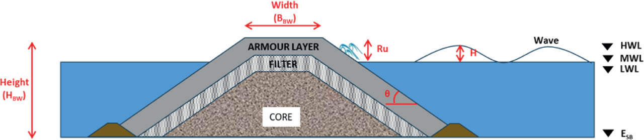
FIGURE 2.
Breakwater configuration used in this study
Source: own work.
Hydrodynamic design parameters were established to reflect typical severe storm conditions, and a significant wave height (H) of 3.0 m and a peak wave period (T) of 10 s were adopted for the stability calculations. Water level variations are defined by the high water level (HWL) at +1.85 m, mean water level (MWL) at +1.05 m, and low water level (LWL) at +0.30 m relative to chart datum. These values ensure that the analysis considers the most critical scenarios for armor stability, including the maximum expected wave attack combined with high water levels, which may increase overtopping risks. The adopted parameters provide a consistent and realistic basis for evaluating the performance of different armor types and slope configurations under severe coastal conditions.
The design of the armor layer followed established empirical methods to ensure hydraulic stability under the adopted design wave conditions. The procedure consists of determining the breakwater crest elevation, calculating the required armor unit weight, and estimating the number of armor units needed to achieve the specified layer thickness and stability.
The total height of the breakwater crest (HBW) was determined to prevent overtopping under the design wave conditions. This value was calculated using the following equation:
where: ESB is the elevation of seabed level, HWL is the high water level, Ru is the wave run-up and 0.5 m is the additional freeboard for safety.The wave run-up (Ru) was estimated based on the Iribarren number (Ir), which characterizes the slope and wave steepness using empirical relationships between Ir and the relative wave run-up (Ru/H), as presented in Figure 3. The Iribarren number (Ir) is calculated as follows:
where: θ is the slope angle of the breakwater, H is the design wave height and L0 is the deepwater wavelength, given by where: T is the peak wave period.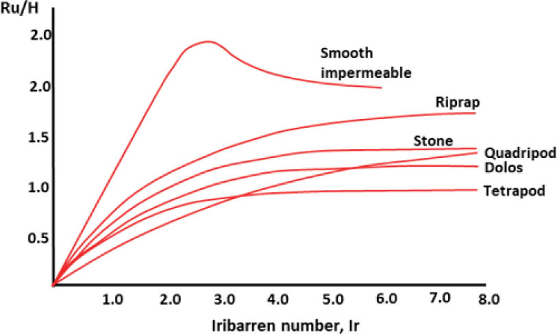
FIGURE 3.
Iribarren number (Ir) and relative wave run-up (Ru/H) curves for different types of armor
Source: Triatmodjo (2016).
The required armor unit weight (W) is calculated using Hudson's formula (Hudson, 1959), which ensures stability against wave forces:
where: γr and γa are the unit weights of the armor material (concrete) and seawater, respectively, and KD is the stability coefficient, which depends on the armor unit type (values provided in Table 1).TABLE 1.
Stability coefficient for different armor types
| Armor | Stability coefficient (KD) [-] | Layer coefficient (kΔ) [-] | Porosity (P) [%] |
|---|---|---|---|
| Tetrapod | 8.0 | 1.04 | 50 |
| Tribar | 10.0 | 1.13 | 54 |
| Dolos | 31.8 | 1.0 | 63 |
[i] Source: Triatmodjo (2016).
The width of the breakwater crest (BBW) was calculated to accommodate the minimum number of armor units, ensuring sufficient layer thickness and structural stability. It is given by:
where: n is the number of armor units across the crest (typically above 3) and kΔ is the layer coefficient, dependent on the armor type, as shown in Table 1.The total number of armor units required per armor layer area (N) was determined to ensure complete coverage, taking into account the armor porosity. It is calculated using:
where: A is the layer plan area, and P is the porosity percentage of the armor layer (values in Table 1).In this study, the armor units were assumed to be constructed from plain unreinforced mass concrete. This approach reflects the standard practice for armor units of moderate size (up to approximately 2–3 t), where the risk of structural failure due to tensile stresses is minimal under typical handling and hydraulic loading conditions. Moreover, avoiding reinforcement reduces both material costs and the overall environmental footprint of the breakwater, aligning with the objective of identifying material-efficient and low-carbon design solutions.
The embodied carbon assessment for the armor units in this study was conducted using a ‘cradle-to-gate’ framework, encompassing life cycle stages A1–A3 as defined in BS EN 15978 (British Standards Institute [BSI], 2011). The total embodied carbon (EC) associated with each design scenario was calculated using the following equation:
where: C is the quantity of concrete material used [kg] and CF is the embodied carbon factor, taken as 0.138 kg CO2e·kg−1.This carbon factor corresponds to concrete grade C32/40, which is widely employed in marine structures, and was established based on a comprehensive carbon and energy inventory compiled using the circular ecology approach (Circular Ecology, n.d.). This methodological approach adheres to recognized standards for life cycle assessment, ensuring a consistent and robust evaluation of the carbon footprint associated with the production of concrete armor units from raw material extraction to the completion of manufacturing processes at the factory gate.
Results and discussion
This section presents and analyzes the calculated armor unit requirements, total material quantities, and embodied carbon estimates for each slope-armor combination investigated. The results allow a comparative assessment of the design efficiency across the three armor unit types – tetrapods, tribars, and dolos – under three breakwater slope configurations of 1 : 1.5, 1 : 2, and 1 : 3. The discussion highlights trends in the required armor sizes, number of units, total material volume, and their implications for embodied carbon, stability performance, and sustainable breakwater design.
Figure 4 presents the required armor unit weights for each armor type (tetrapods, tribars, and dolos) across the three investigated slope configurations (1 : 1.5, 1 : 2, and 1 : 3). The results show a clear trend: as the slope becomes gentler, the required individual armor unit weight decreases substantially for all armor types. These trends reflect the fundamental relationship between the slope angle and wave energy dissipation: gentler slopes spread the wave energy over a larger area, reducing the forces acting on individual armor units and allowing for smaller units to achieve hydraulic stability. Among the three armor types, dolos consistently requires the lowest individual unit weights for all slope configurations, which aligns with their high stability coefficient (KD) and superior interlocking performance. This highlights the potential for significant material and embodied carbon savings when dolos are used, particularly when combined with gentler slopes. However, these material advantages should be weighed against practical considerations such as placement complexity and potential breakage risk during construction.
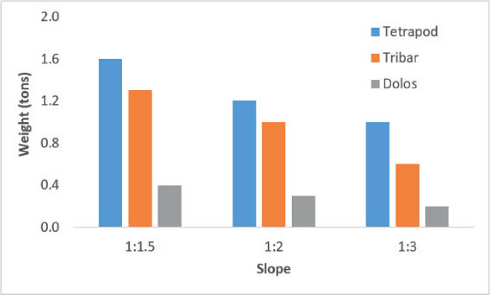
FIGURE 4.
Required armor unit weights for tetrapods, tribars, and dolos across different breakwater slope configurations
Source: own work.
The calculated total crest height of the breakwater, determined using the design wave conditions and run-up calculations, was consistently 13 m above the seabed level for all armor types and slope configurations. This consistent crest height ensures comparable protection against overtopping across design scenarios, allowing a direct assessment of other geometric parameters, such as crest width.
Figure 5 presents the required widths of breakwater crests for tetrapods, tribars, and dolos across the three investigated slopes. The results indicated that the crest width generally decreased as the slope became gentler. For example, in the tetrapod case, the crest width reduced from approximately 2.6 m at a 1 : 1.5 slope to 2.1 m at a 1 : 3 slope. A similar trend was observed for tribars and dolos, with dolos consistently requiring the narrowest crest widths across all the slopes. This is attributed to the higher stability coefficient (KD) of dolos, which allows fewer and smaller units to achieve the required layer thickness, thereby reducing the required crest width.
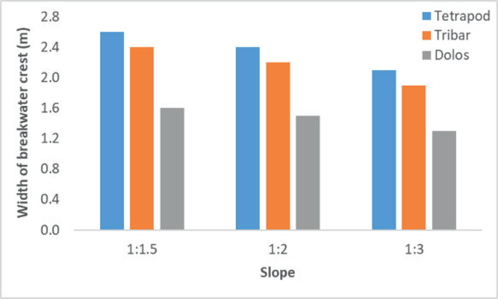
FIGURE 5.
Required breakwater crest widths for tetrapods, tribars, and dolos across different slope configurations
Source: own work.
These findings imply that selecting armor units with higher hydraulic stability not only minimizes the required material volumes but also allows more compact crest dimensions. This can be advantageous in projects with limited spatial availability or where minimizing the footprint of the structure is a priority. However, as with armor weight reduction, these geometric benefits must be balanced with practical considerations related to construction feasibility, placement accuracy, and long-term maintenance.
Figure 6 shows the calculated number of armor units required per 10 m2 of armor layer area for tetrapods, tribars, and dolos across the three slope configurations. The results reveal a clear trend: as the slope becomes gentler from 1 : 1.5 to 1 : 3, the number of armor units required per unit area increases significantly for all armor types. For example, the number of tetrapod units per 10 m2 increased from 15 units on a 1 : 1.5 slope to 24 units on a 1 : 3 slope. Similarly, tribars increased from 16 to 25 units, while dolos showed the largest increase, from 27 to 42 units, over the same slope range.
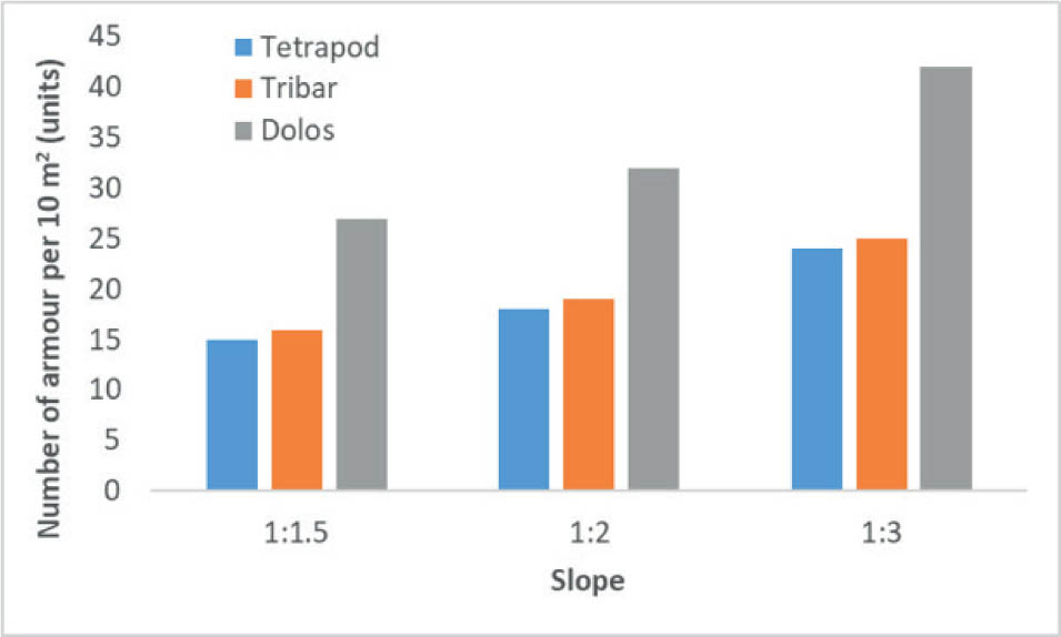
FIGURE 6.
Required number of armor units for tetrapods, tribars, and dolos across different slope configurations
Source: own work.
This increase in the number of units with gentler slopes is expected because a flatter slope expands the surface area of the armor layer, thus requiring more units to maintain the necessary layer thickness and porosity. Among the three armor types, dolos consistently requires the highest number of units per area on each slope, despite their smaller individual unit sizes. While the high stability coefficient of dolos allows smaller units to achieve hydraulic stability, their interlocking geometry requires a greater quantity of units to form a stable layer.
These findings highlight an important trade-off: although gentler slopes with efficient armor types such as dolos reduce individual unit weight and total material mass, they also lead to a substantial increase in the number of units to handle and place. This can complicate construction logistics and increase placement time and costs. Therefore, practical considerations, such as available construction resources, placement accuracy, and long-term maintenance, should be carefully evaluated when selecting slope configurations and armor types.
While the preceding discussions have detailed the required armor unit weights, crest widths, and number of armor units necessary for each slope and armor type, a comprehensive evaluation of breakwater design efficiency must also account for environmental impacts. The use of concrete in armor units contributes substantially to the overall carbon footprint of coastal structures, given the high emissions associated with portland cement production. Therefore, in addition to assessing material quantities, this study evaluates the embodied carbon associated with each slope-armor combination to provide a more holistic understanding of the sustainability implications of breakwater design choices. The results of the embodied carbon calculations are presented in Figure 7.
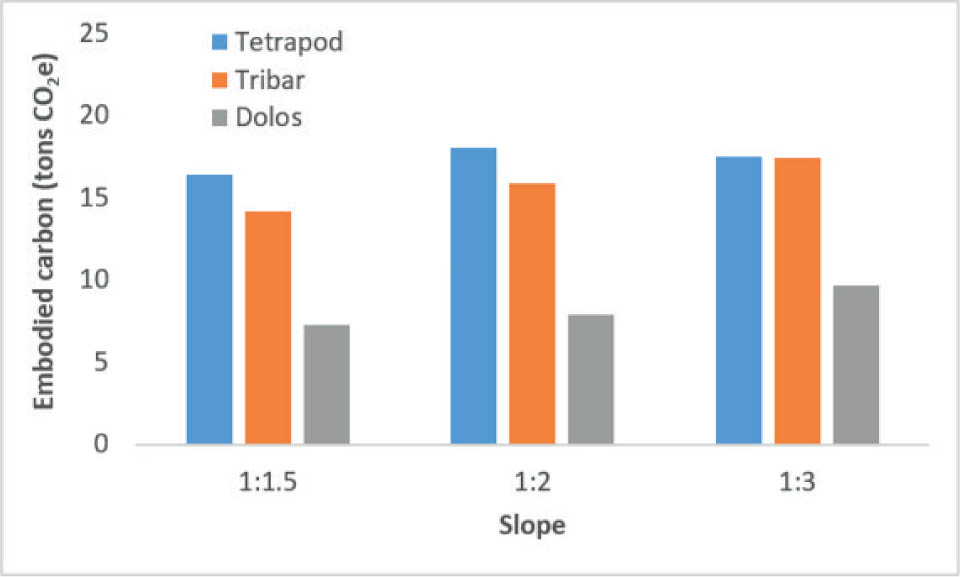
FIGURE 7.
Embodied carbon emissions per meter length of breakwater across different slope configurations
Source: own work.
The results show that embodied carbon increases consistently as the slope becomes gentler from 1 : 1.5 to 1 : 3 for all armor types. For example, in the tetrapod case, the embodied carbon increases from approximately 16 t CO2e at a 1 : 1.5 slope to over 22 t CO2e at a 1 : 3 slope. A similar trend was observed for tribars, which increased from approximately 14 to 18 t CO2e, while dolos showed the lowest embodied carbon across all slopes, rising from approximately 7 t CO2e to 10 t CO2e.
Although embodied carbon is calculated using a constant carbon factor (0.138 kg CO2e·kg−1) and is therefore linearly proportional to concrete mass, the trend observed in Figure 7 differs from that shown in Figure 4 because the two figures represent different mass bases. Figure 4 presents the required weight of individual armor units, which decreases as the slope becomes gentler. In contrast, Figure 7 reflects the total embodied carbon per meter length of breakwater, which depends on the total concrete volume required to construct the armor layer.
For gentler slopes, while smaller individual armor units are sufficient to maintain hydraulic stability, the surface area of the armor layer per meter length increases substantially. This leads to a significantly higher number of armor units, as shown in Figure 6, and consequently a larger total concrete volume. As a result, the total embodied carbon increases with gentler slopes despite the reduction in individual unit weight. Similar trade-offs between armor unit size, quantity, and overall material demand have been reported in previous hydraulic studies focusing on armor stability and slope effects (Hanzawa et al., 2012; Maryuama et al., 2014; Mitsui et al., 2016; Safan et al., 2018; Mares-Nasarre et al., 2022; Yuksel et al., 2022). However, those studies primarily addressed hydraulic performance, whereas the present results extend this body of knowledge by demonstrating that slope geometry and armor type selection also exert a significant influence on the carbon footprint of breakwater structures.
Despite the increase in total material demand for gentler slopes, dolos consistently result in substantially lower embodied carbon than tetrapods and tribars across all slope configurations. This advantage is attributed to the high stability coefficient of dolos, which enables the use of smaller unit sizes and lower total concrete volumes, even when accounting for the increased number of units. These findings highlight the importance of jointly considering slope geometry, armor type, and total material demand when aiming to minimize the environmental impact of rubble mound breakwaters.
Conclusion
In this study, the design efficiency of rubble mound breakwaters armored with three types of concrete armor across three slope configurations (1 : 1.5, 1 : 2, and 1 : 3) was investigated. The analysis focused on the required armor unit sizes, number of units per area, crest geometry, and embodied carbon emissions to identify optimal combinations for material efficiency and sustainability.
The results showed that gentler slopes significantly reduced the required individual armor unit weights owing to the decreased wave energy per unit area. However, flatter slopes simultaneously increased the number of armor units required per unit area as the armor layer surface area expands. Dolos consistently demonstrated the highest material efficiency, requiring the smallest individual unit sizes, and resulting in the lowest total concrete volumes and embodied carbon across all slope configurations. In contrast, tetrapods and tribars demanded larger total volumes and generated higher embodied carbon emissions, particularly on gentler slopes.
Despite these material and environmental advantages, the increased number of armor units associated with flatter slopes, especially for dolos, can introduce practical challenges during construction, including more complex placement logistics and potentially higher labor costs. These findings underscore the importance of balancing the hydraulic stability, material efficiency, and embodied carbon considerations with practical construction constraints.
Overall, this study highlights that selecting high-efficiency armor units, such as dolos, combined with appropriately optimized slope configurations, offers a viable strategy for reducing material consumption and carbon footprint in breakwater design. Integrating embodied carbon assessments into the early stages of coastal infrastructure planning provides valuable insights into achieving more sustainable, cost-effective, and resilient shoreline protection solutions.
Acknowledgments
The authors express their sincere gratitude to the Karbonara Research Institute for the invaluable support and resources provided throughout this research. Special thanks are extended to the Civil Engineering Department of BINUS University for its continuous guidance, encouragement, and access to the necessary facilities and equipment.