
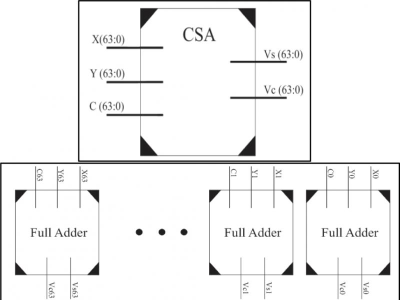
Figure 1.
Carry save Adder: (a) Top View Design (b) Internal Architecture
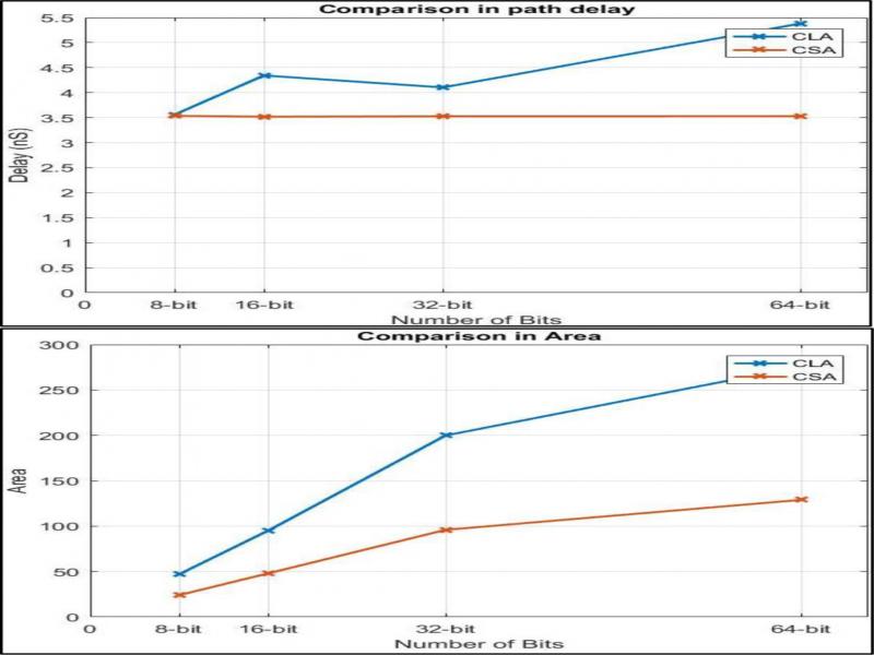
Figure 2.
Delay-Area analysis of CSA vs CLA implementations (8–64 bit)
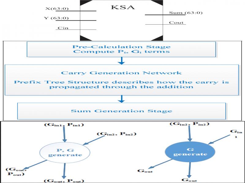
Figure 3.
Kogge Stone Adder: (a) Top View Design of KSA (c) KSA Stages (c) Group generation and propagation
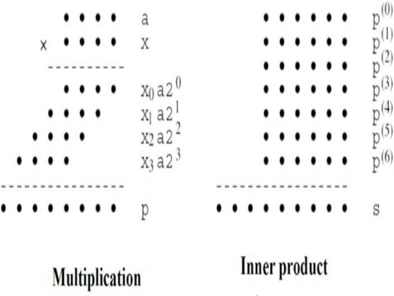
Figure 4.
Dot notation of Multi-operand addition for multiplication and inner-product computation
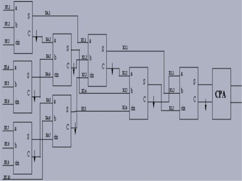
Figure 5.
Multi-operand addition for 10 operands.
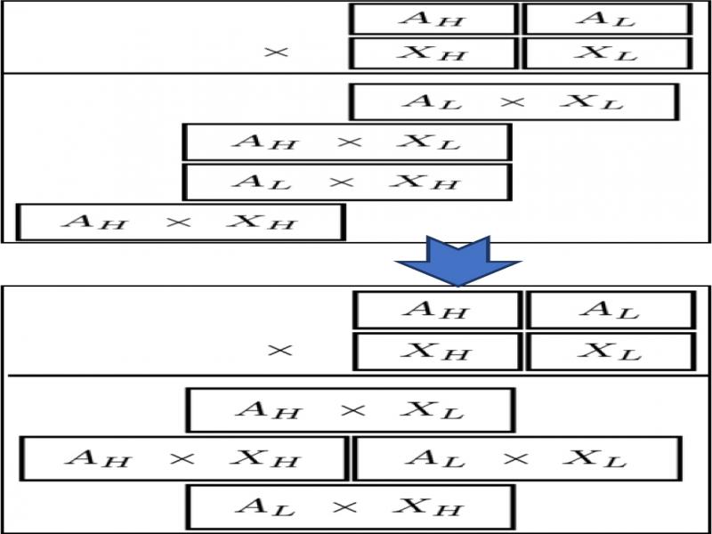
Figure 6.
Aligning Partial Products.
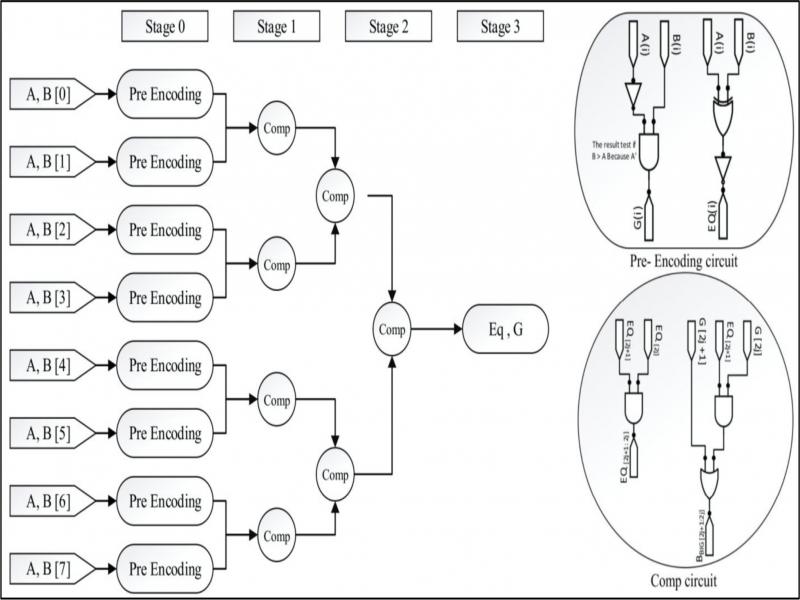
Figure 7.
The complete design of8- Bit Comparatorincluding Pre- Encoding circuit and Comp circuit
TABLE I.
RADIX-8 BOOTH ENCODING.
| Inputs (bits of M-bit multiplier) | Partial Product | |||
|---|---|---|---|---|
| xi+2 | xi+1 | xi | xi−1 | PPRi |
| 0 | 0 | 0 | 0 | 0 |
| 0 | 0 | 0 | 1 | A |
| 0 | 0 | 1 | 0 | A |
| 0 | 0 | 1 | 1 | 2A |
| 0 | 1 | 0 | 0 | 2A |
| 0 | 1 | 0 | 1 | 3A |
| 0 | 1 | 1 | 0 | 3A |
| 0 | 1 | 1 | 1 | 4A |
| 1 | 0 | 0 | 0 | -4A |
| 1 | 0 | 0 | 1 | -3A |
| 1 | 0 | 1 | 0 | -3A |
| 1 | 0 | 1 | 1 | -2A |
| 1 | 1 | 0 | 0 | -2A |
| 1 | 1 | 0 | 1 | -A |
| 1 | 1 | 1 | 0 | -A |
| 1 | 1 | 1 | 1 | 0 |
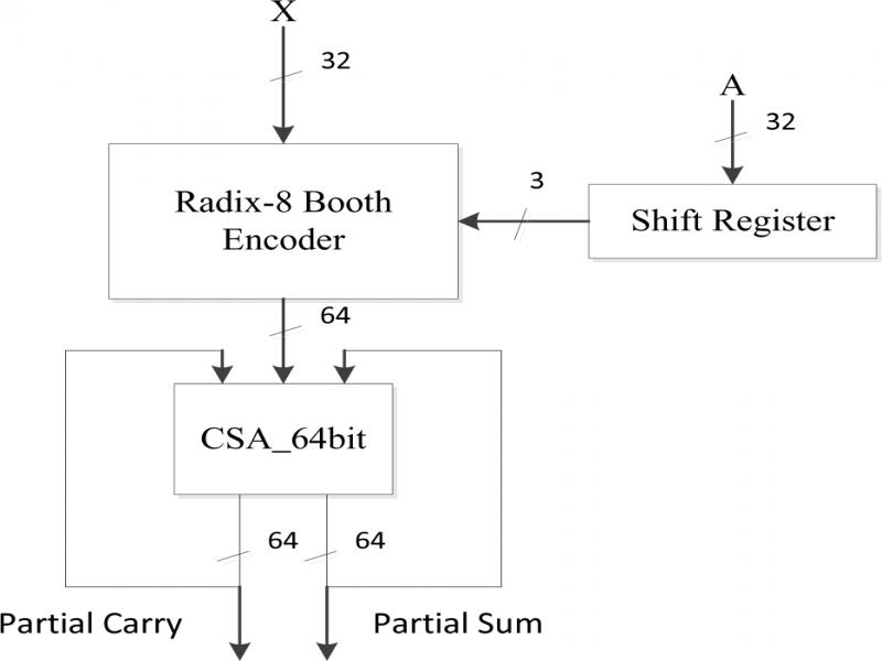
Figure 8.
Design of Radix-8 Booth 32-bit multiplier
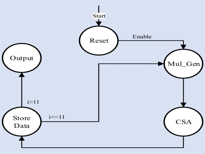
Figure 9.
State machine diagram for 32-bit Booth multiplier.
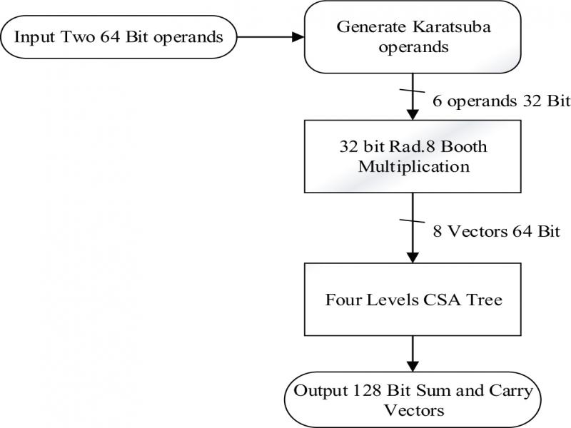
Figure 10.
Design of 64-bit CSA Based Radix-8 Booth, Wallace Tree Karatsuba multiplier.
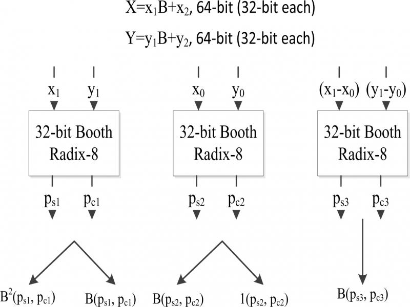
Figure 11.
Graphical approaches to demonstrate the carry error (the mid-carry problem), here we have two cases: Case I- ps1+ pc1 = might result in carry, result = 65-bit (wrong). Carry must be discarded and Case II- ps1+ ps2 = might result in carry, result = 65-bit (correct). Carry must be considered.
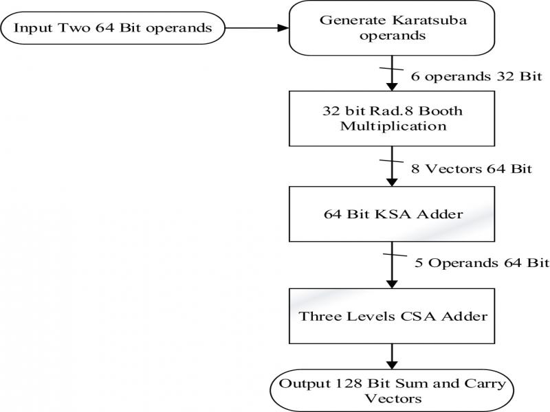
Figure 12.
Design of 64-bit: 64-bit CSA Based Radix-8 Booth, KSA Based Karatsuba multiplier.
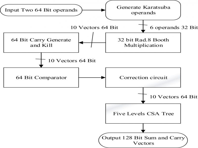
Figure 13.
Karatsuba multiplication based on CSA and comparator.
TABLE II.
COMPARISON BETWEEN DESIGN II & DESIGN III.
| Design Solutions # | Delay (gate delay) | % Optimization | Area (# of gates) | % Optimization |
|---|---|---|---|---|
| Solution I: using KSA Adder. | 23 | +15% | 6130 | |
| Solution II: using Comparator unit. | 27 | 3712 | +50% |
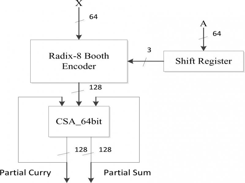
Figure 14.
Design of CSA based Radix-8 Booth 64-bit multiplier.
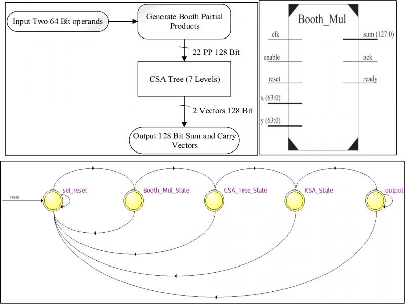
Figure 15.
(a) Design Architecture of WCBM (a) Top Level DiagramWCBM (C) FSM Diagram for WCBM.
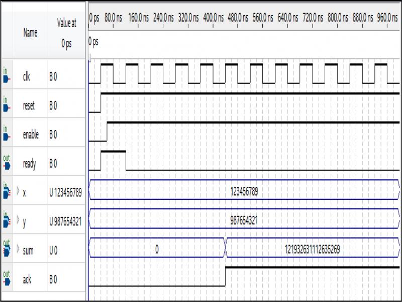
Figure 16.
Sample run example of WCBM process of two 64-bit numbers
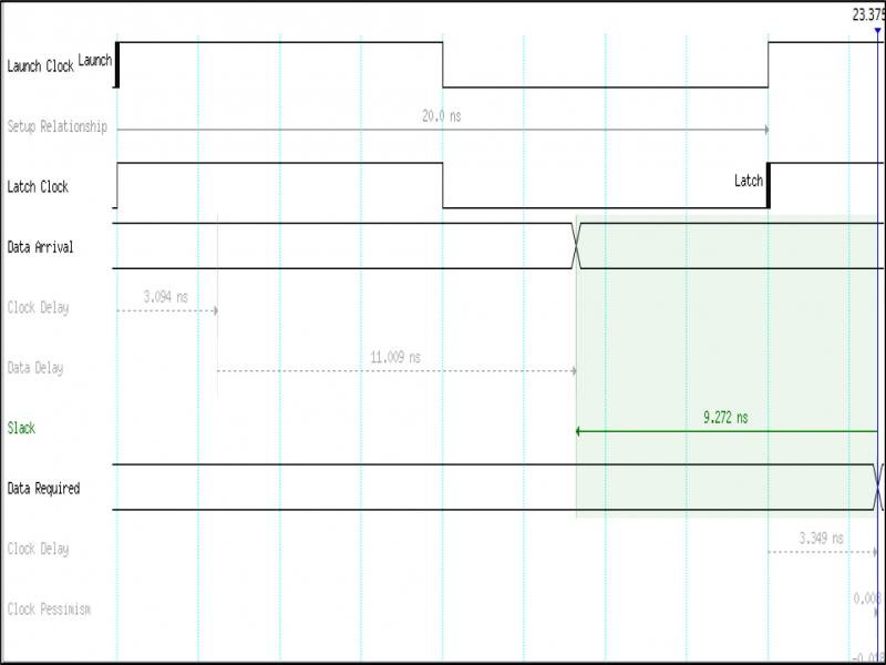
Figure 17.
Waveform sample of the proposed WCBM data delay