
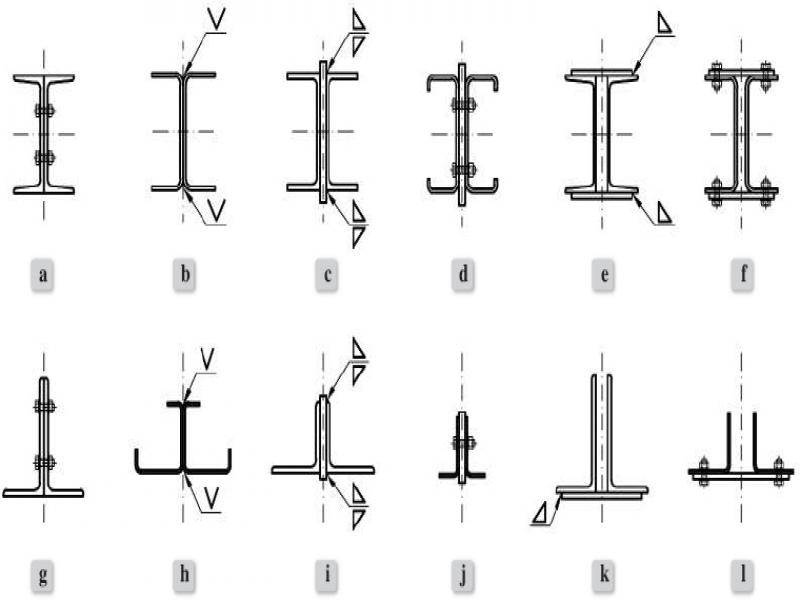
Figure 1.
Examples of composite closely spaced built-up member (CSBUM) sections built of a pair of: (a)–(f) channel sections, (g)–(l) angle sections
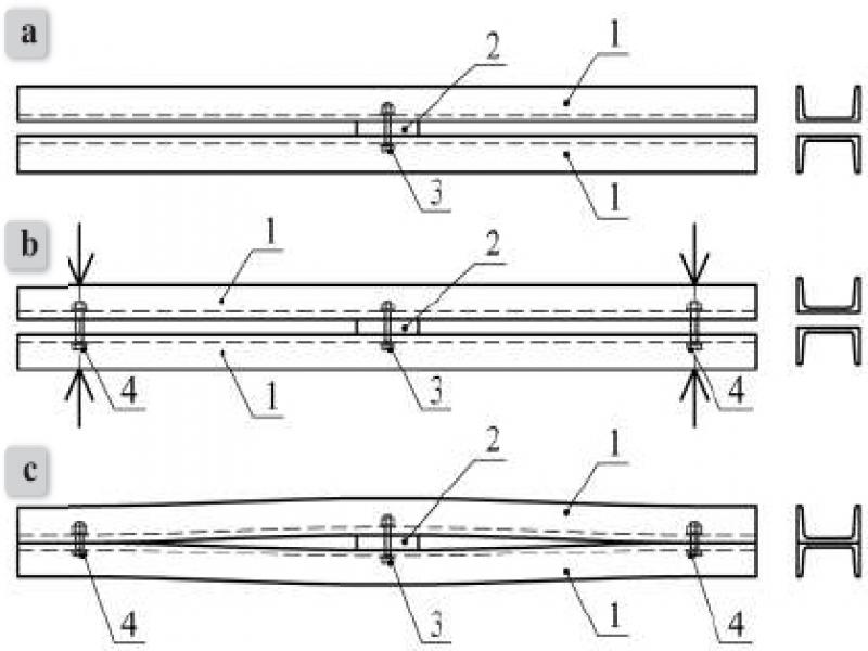
Figure 2.
Bipolar prestressing diagram of prestressed CSBUM with symmetrical boundary conditions [42]
(a) part A, (b) part B, (c) bipolarly prestressed closely spaced built-up member (BPCSBUM)
1 – chord of the CSBUM, 2 – spacer, 3 – spacer connector, 4 – friction grip bolt
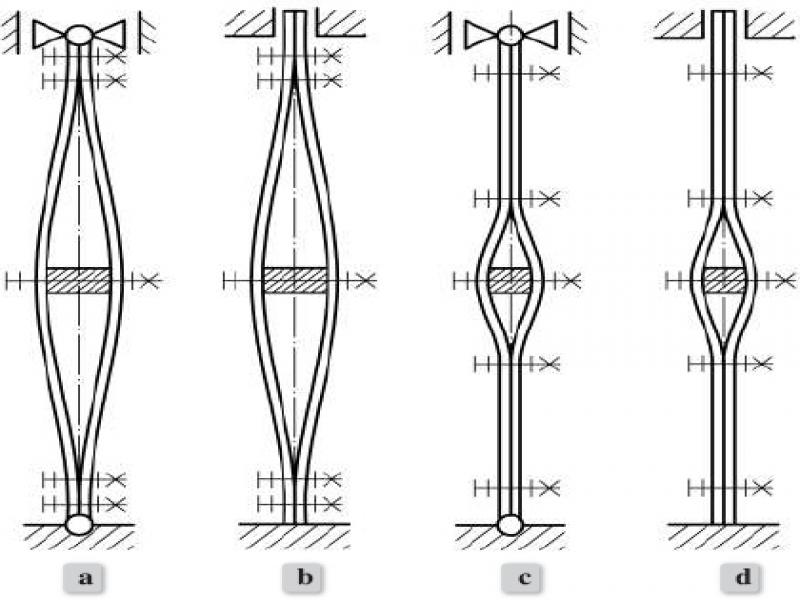
Figure 3.
Exemplary diagrams of BPCSBUMs
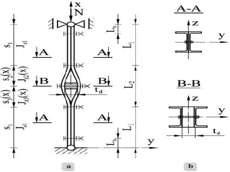
Figure 4.
Geometry of an example BPCSBUM with two-sided pinned support (a) view, (b) cross-sections
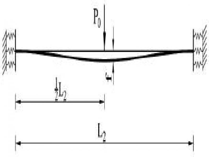
Figure 5.
Static model of the CSBUM chord in the prestressing zone
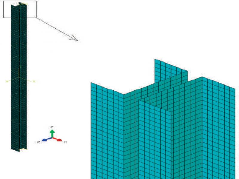
Figure 6.
An example of finite element grid
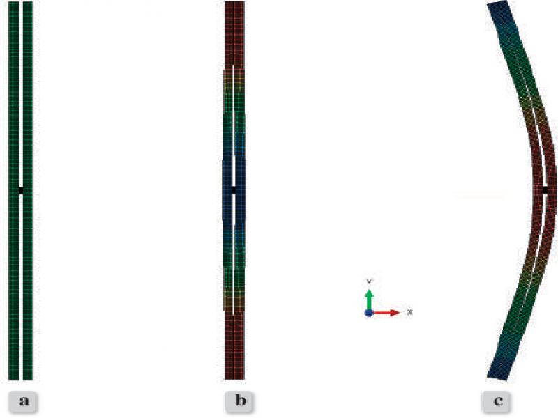
Figure 7.
An example of a BPCSBUM – calculation steps: (a) Initial, (b) Prestressing, (c) Buckling analysis
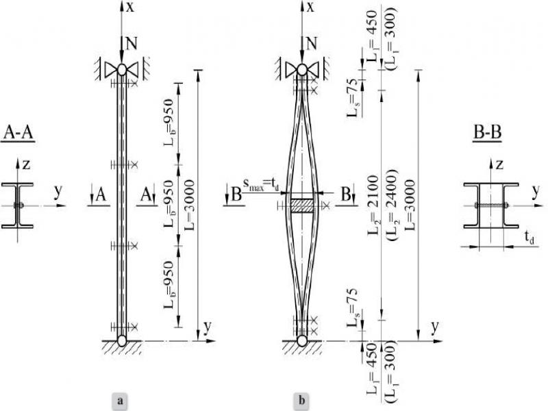
Figure 8.
Calculation example (a) standard CSBUM (b) BPCSBUM
Table 1.
Geometric characteristics of UPE120 and UPE160
| Section | Ach | Jy,ch | Jz,ch | iz,ch | ez,ch |
| [cm2] | [cm4] | [cm4] | [cm] | [cm] | |
| UPE120 | 16.8 | 392 | 60.7 | 1.90 | 2.02 |
| UPE160 | 23.7 | 965 | 114 | 2.19 | 2.20 |
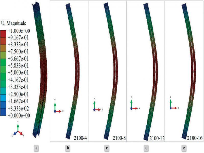
Figure 9.
The result of FEM simulation on BPCSBUM built from a pair of UPE120 channel sections with the length of the prestressing zone L2 = 2100 mm: (a) 3D view, (b)–(e) 2D view according to the thickness of the spacer td: (b) td = 4 mm, (c) td = 8 mm, (d) td = 12 mm, (e) td = 16 mm
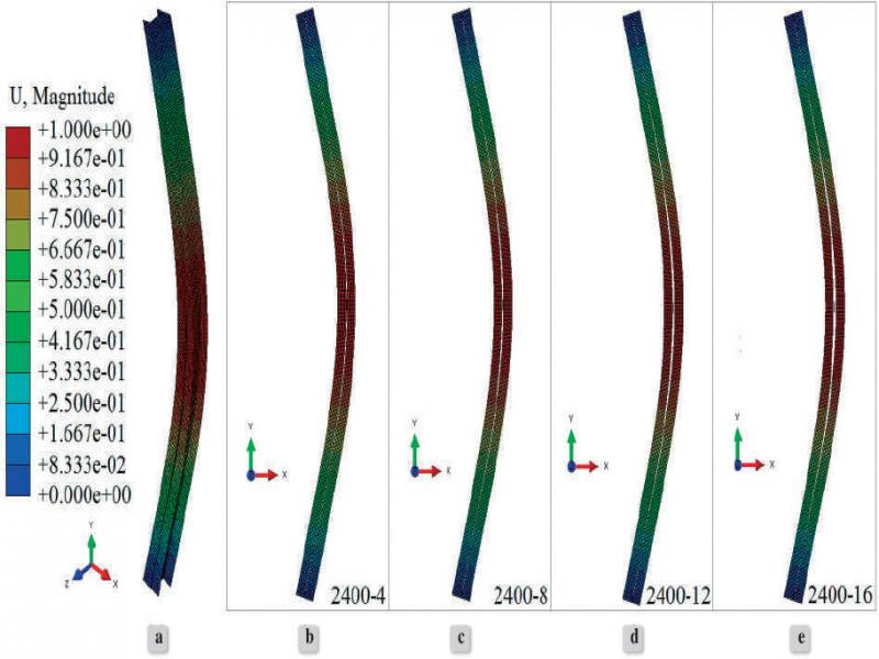
Figure 10.
The result of FEM simulation on BPCSBUM built from a pair of UPE120 channel sections with the length of the prestressing zone L2 = 2100 mm: (a) 3D view, (b)–(e) 2D view according to the thickness of the spacer td: (b) td = 4 mm, (c) td = 8 mm, (d) td = 12 mm, (e) td = 16 mm
Table 2.
Description of the BPCSBUM geometry
| 2xUPE120 | |||||||||
| L2 | [mm] | 2100 | 2400 | ||||||
| td | [mm] | 4 | 8 | 12 | 16 | 4 | 8 | 12 | 16 |
| Jz1(8) | [cm4] | 258.50 | |||||||
| Jz2(x=150.0) (9) | [cm4] | 286.99 | 318.18 | 352.04 | 388.60 | 286.99 | 318.18 | 352.04 | 388.60 |
| Jz,sr (14) | [cm4] | 268.48 | 279.39 | 291.24 | 304.04 | 269.90 | 282.37 | 295.92 | 310.54 |
| 2xUPE160 | |||||||||
| L2 | [mm] | 2100 | 2400 | ||||||
| td | [mm] | 4 | 8 | 12 | 16 | 4 | 8 | 12 | 16 |
| Jz1(8) | [cm4] | 457.42 | |||||||
| Jz2(x=150.0) (9) | [cm4] | 501.02 | 548.42 | 599.62 | 654.60 | 501.02 | 548.42 | 599.62 | 654.60 |
| Jz,sr (14) | [cm4] | 472.68 | 489.27 | 507.19 | 526.43 | 474.86 | 493.82 | 514.30 | 536.29 |
Table 3.
Critical load capacity of BPCSBUM
| L2 | td=Smax | Ncr mod(23) | Ncr,PBSB MES | ζ1 | ζ2 |
|---|---|---|---|---|---|
| [mm] | [mm] | [kN] | [kN] | [%] | [%] |
| 2xUPE120 | |||||
| 2100 | 4 | 601.2 | 594.4 | 1.14 | 18.72 |
| 8 | 624.9 | 631.8 | -1.09 | 23.40 | |
| 12 | 650.6 | 671.1 | -3.06 | 28.48 | |
| 16 | 678.3 | 712.0 | -4.73 | 33.95 | |
| 2400 | 4 | 615.2 | 570.9 | 7.76 | 21.49 |
| 8 | 643.4 | 608.1 | 5.81 | 27.05 | |
| 12 | 673.9 | 647.7 | 4.05 | 33.08 | |
| 16 | 706.8 | 689.5 | 2.51 | 39.57 | |
| 2xUPE160 | |||||
| 2100 | 4 | 1060.3 | 1043.0 | 1.66 | 17.32 |
| 8 | 1096.5 | 1097.0 | -0.05 | 21.32 | |
| 12 | 1135.5 | 1154.2 | -1.62 | 25.64 | |
| 16 | 1177.3 | 1180.2 | -0.25 | 30.26 | |
| 2400 | 4 | 1083.1 | 1005.8 | 7.69 | 19.84 |
| 8 | 1125.9 | 1061.0 | 6.12 | 24.57 | |
| 12 | 1172.1 | 1119.1 | 4.74 | 29.69 | |
| 16 | 1221.7 | 1187.8 | 2.85 | 35.17 | |
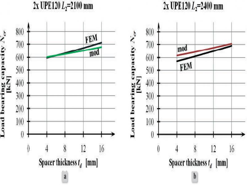
Figure 11.
Comparison of numerical (FEM) and analytical (mod) results for BPCSBUM: (a) 2xUPE120, L2 = 2100 mm, (b) 2xUPE120, L2 = 2400 mm
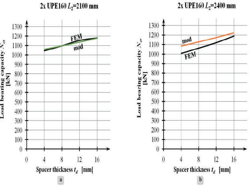
Figure 12.
Comparison of numerical (FEM) and analytical (mod) results for BPCSBUM: (a) 2xUPE160, L2 = 2100 mm, (b) 2xUPE160, L2 = 2100 mm
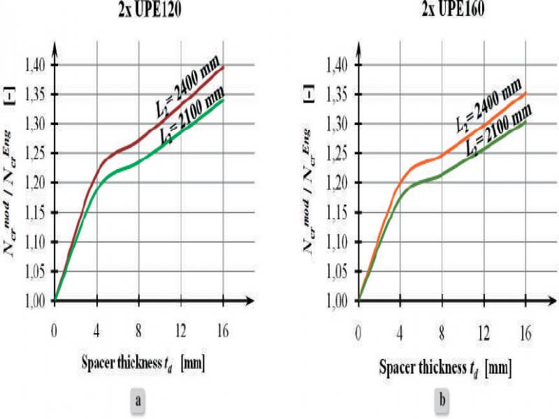
Figure 13.
Critical load bearing capacity of BPCSBUM built of: (a) 2xUPE120, (b) 2xUPE160