

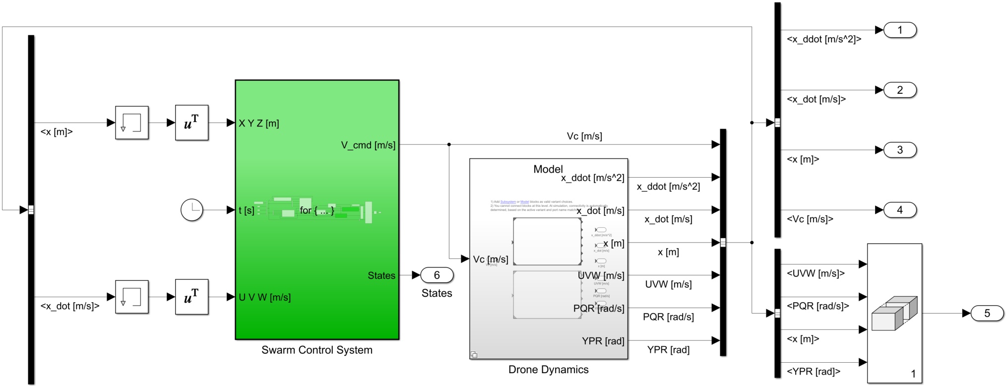
Figure 1.
Top-level block diagram of the swarm simulator
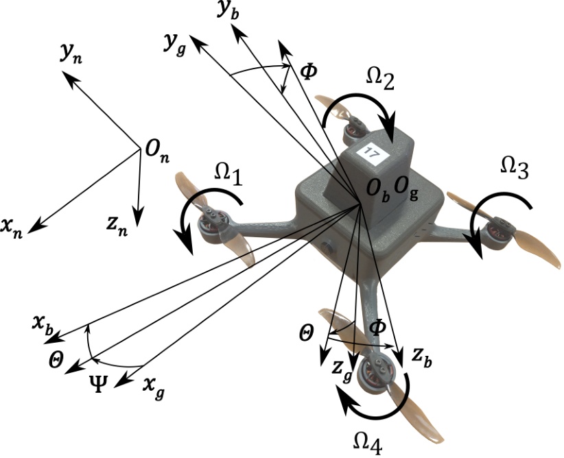
Figure 2.
Coordinate systems used in the simulation
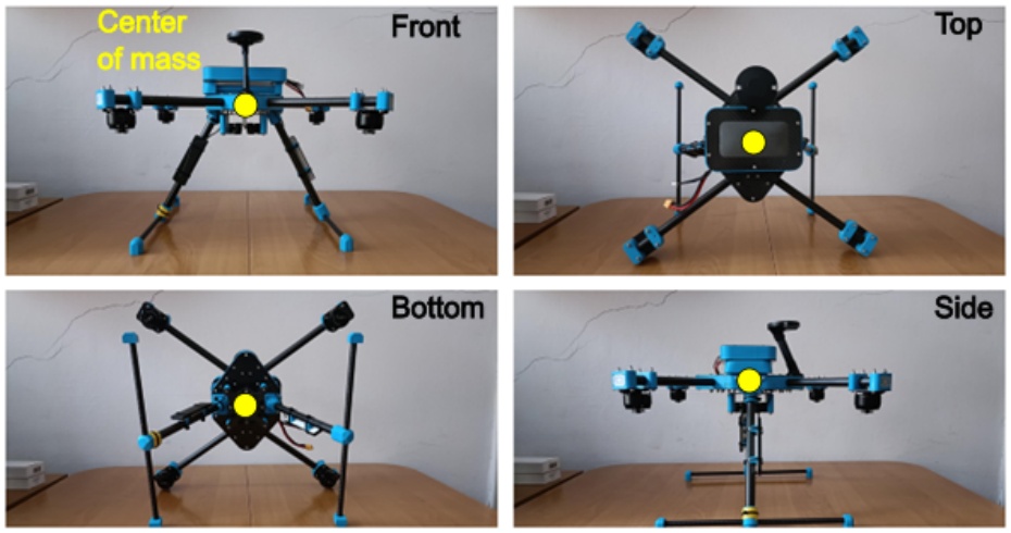
Figure 3.
Leader (with propellers removed)
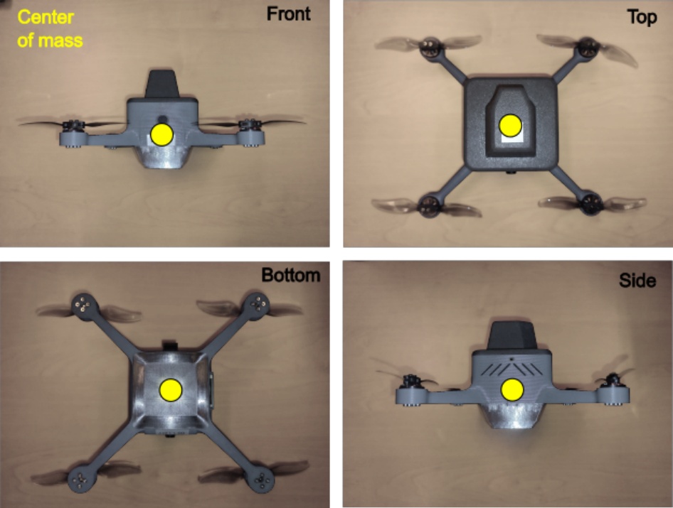
Figure 4.
Follower
Table 1.
Leaders’ parameters
| Parameter | Value |
|---|---|
| Mass [kg] | 2.182 |
| Moment of inertia Ixx [kg m2] | 0.055744 |
| Moment of inertia Iyy [kg m2] | 0.058427 |
| Moment of inertia Izz [kg m2] | 0.068685 |
| 1-st rotor location r1 [m] | [0.195, 0.135, 0]] |
| 2-nd rotor location r2 [m] | [-0.195, 0.135, 0] |
| 3-rd rotor location r3 [m] | [-0.195, -0.135, 0] |
| 4-th rotor location r4 [m] | [0.195, -0.135, 0] |
| Propeller diameter [m] | 0.3048 |
Table 2.
Followers’ parameters
| Parameter | Value |
|---|---|
| Mass [kg] | 0.274 |
| Moment of inertia Ixx [kg m2] | 0.000466 |
| Moment of inertia Iyy [kg m2] | 0.000476 |
| Moment of inertia Izz [kg m2] | 0.002024 |
| 1-st rotor location r1 [m] | [0.0775, 0.0775, 0] |
| 2-nd rotor location r2 [m] | [-0.0775, 0.0775, 0] |
| 3-rd rotor location r3 [m] | [-0.0775, -0.0775, 0] |
| 4-th rotor location r4 [m] | [0.0775, -0.0775, 0] |
| Propeller diameter [m] | 0.1016 |
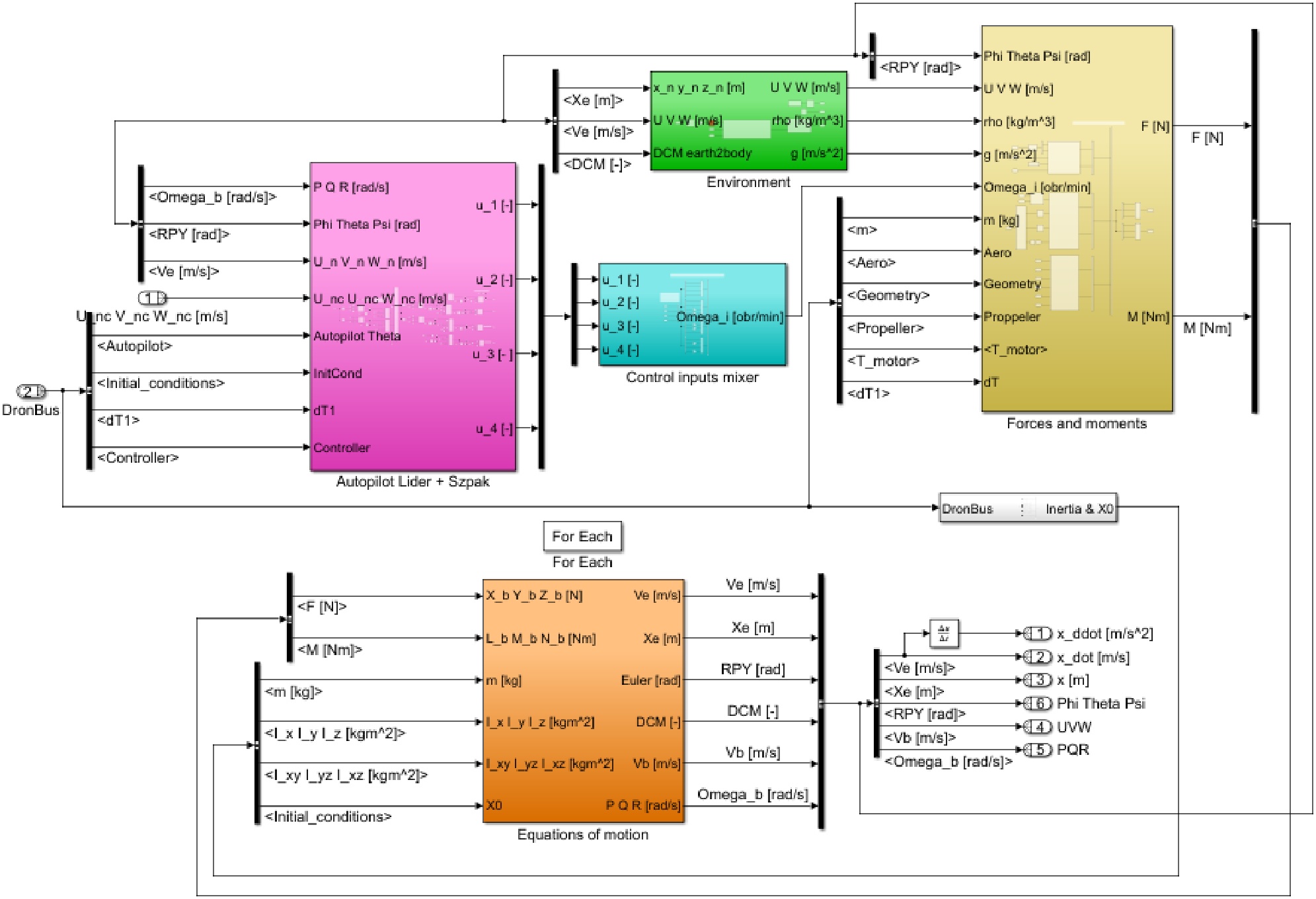
Figure 5.
Drone’s dynamic model developed in Simulink
Table 3.
Leaders’ control rules
| Rule | Description |
|---|---|
| Alignment | It ensures that the Leaders fly at an average velocity of all Leaders. |
| Cohesion | It ensures that the Leaders fly in a flock. |
| Separation | It ensures that the Leaders do not collide with each other. |
| Avoidance | It ensures that the Leaders do not collide with known, static obstacles. |
| Targeting | It ensures that the Leaders fly through their designated waypoints. |
Table 4.
Followers’ control rules
| Rule | Description |
|---|---|
| Alignment | It ensures that the Followers fly with the velocity of their Leader. |
| Cohesion | It ensures that the Followers tend to move to their Leader’s position. |
| Separation | It ensures that the Followers do not collide with each other within their formation. |
| Avoidance | It ensures that the Followers do not collide with known, static obstacles. |
| Formation | It ensures that the Followers keep the designated distance from each other within their formation. |
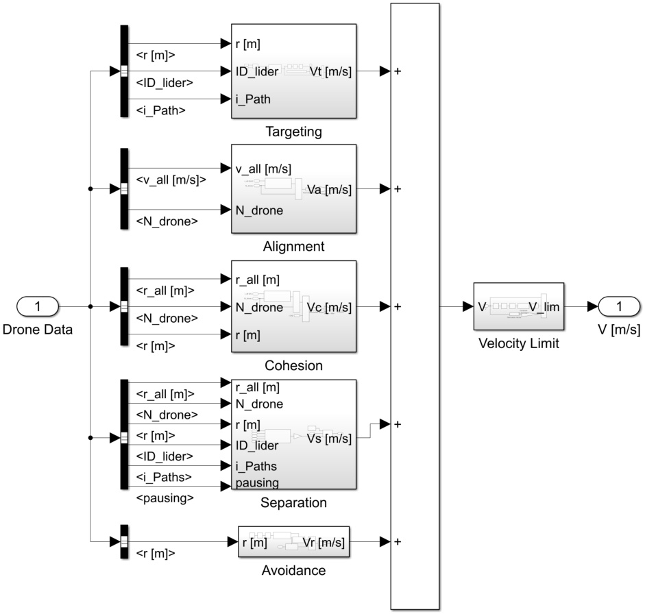
Figure 6.
Leaders’ control rules applied in Simulink
Table 5.
Leaders’ states
| No. | Name | Description |
|---|---|---|
| 0 | Cruise | Main state in which the Leader flies through its designated waypoints. The Leader is allowed to wait in each of them for a specified amount of time, before flying to the next one. |
| 1 | Takeoff | State that is applied to the Leaders at the beginning of the mission. It indicates that the Leader is waiting in the base for the time when it is supposed to ascend or that it is ascending and waiting for the Followers to join it. |
| 2 | Landing | State in which the Leader, after reaching the last waypoint, is descending until it touches the ground. |
| 3 | Malfunction | State in which all communication with the Leader was lost and it is excluded from further calculations. |
| 4 | Standby | State in which the Leader awaits in the base for further instructions. |
| 6 | Return | State in which the Leader returns to the base. |
Table 6.
Followers’ states
| No. | Name | Description |
|---|---|---|
| 0 | Cruise | Main state in which the Follower flies in a formation and follows its Leader. |
| 1 | Takeoff | State that is applied to the Followers at the beginning of the mission. It indicates that the Follower is waiting in the base for the time of ascend or that it is ascending vertically before joining its Leader and forming a formation. |
| 2 | Landing | State in which the Follower is descending until it touches the ground. |
| 3 | Malfunction | State in which all communication with the Follower was lost and it is excluded from further calculations. |
| 4 | Standby | State in which the Follower awaits in the base for further instructions. |
| 5 | Flight to the Leader | State in which the Follower performs an independent flight to the Leader after takeoff from the base when one of the formations needs reconfiguration. |
| 6 | Return | State in which the Follower returns to the base after one of the formations needed reconfiguration. |
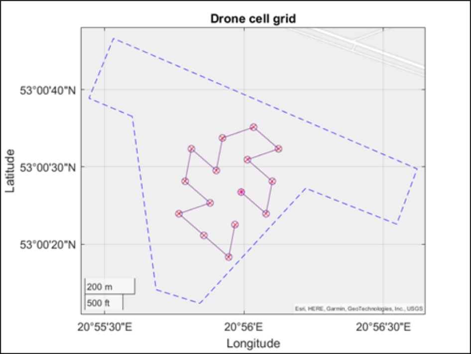
Figure 7.
The snake pattern for a grid coverage
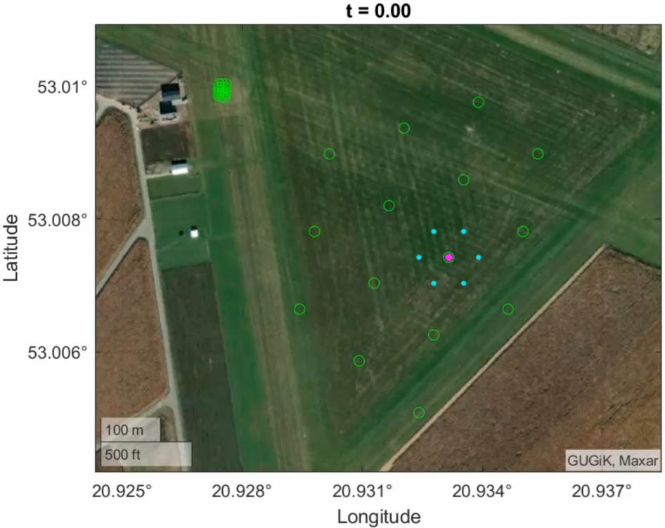
Figure 8.
Beginning of the mission
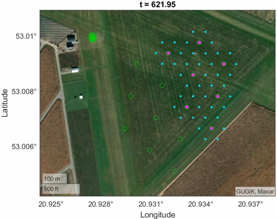
Figure 9.
Drones filling up the grid
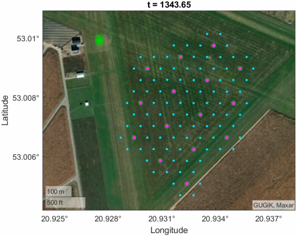
Figure 10.
All of the drones are in the air
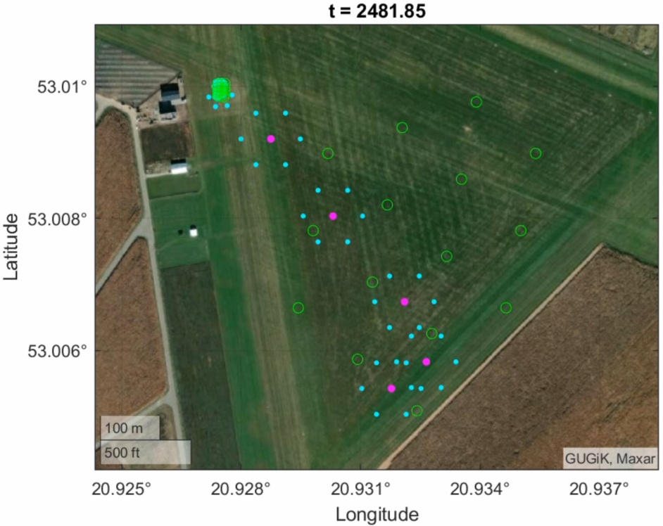
Figure 11.
Return to the landing zone