

1. Introduction
The integration of robotics into everyday human activities has seen significant advancements in recent years, particularly in the domain of HRI [1, 2]. HRI focuses on the collaborative interactions between humans and robots, emphasizing the importance of intuitive communication methods. As robots are increasingly deployed in service roles, ranging from healthcare [3] to domestic assistance, the need for natural and efficient control mechanisms has become paramount. Gesture recognition, as a form of non-verbal communication, offers a promising solution, allowing users to control robots through simple hand movements without the need for physical interfaces [4].
In the context of gesture recognition, various methodologies have been explored. Traditional approaches often rely on depth sensors and complex algorithms, which can be cumbersome and limited in dynamic environments. Recent advancements in machine learning and computer vision have facilitated the development of more sophisticated gesture recognition systems. Notably, the MediaPipe library has emerged as a powerful tool for real-time hand tracking and gesture recognition, enabling the extraction of key points from hand movements with high accuracy [5]. Deep learning techniques have been used to recognize hand gestures in real time for controlling wheeled robots [8]. Artificial neural networks have also been applied to detect hand gestures for smart home functions [9]. Machine learning methods, particularly MediaPipe, have been used for gesture-based computer mouse control [10].
Recent advances in hand gesture recognition have led to the development of more accurate and efficient models across diverse data modalities. A real-time online gesture recognition system using Continual Graph Transformers was proposed, achieving robust recognition with spatial and temporal modeling through S-GCN and a Transformer-based Graph Encoder, evaluated on SHREC’21 [15]. A comprehensive survey covering the period from 2014 to 2024 reviewed RGB, skeleton, depth, EMG, EEG, and multimodal data, identifying trends and challenges in continuous gesture recognition [16]. A hybrid architecture combining BiLSTM, metaheuristic optimization, and a U-Net-MobileNetV2 encoder was introduced for sEMG-based classification, achieving over 90% accuracy across six datasets [17]. Deep learning with EMG signals has also been used to enhance hand gesture recognition performance, highlighting its potential in prosthetics and assistive technologies [18]. Moreover, the TCNN-KAN model, integrating Kolmogorov-Arnold Networks and pruning techniques, was proposed to optimize CNN-based gesture recognition using semg, significantly improving accuracy and computational efficiency [19]. Collectively, these works demonstrate the potential of hybrid deep learning models and advanced optimization techniques to improve gesture recognition performance across modalities and real-world applications.
Furthermore, the implementation of machine learning techniques, particularly Support Vector Machine (SVM), has proven effective for gesture classification tasks. SVM models excel in high-dimensional spaces, making them well-suited for applications involving complex feature sets derived from hand gestures [6, 7]. The use of these techniques not only enhances recognition accuracy but also contributes to the seamless integration of HRI systems within robotic frameworks.
The Robot Operating System (ROS) has significantly influenced the development of robotics applications by providing a flexible framework for robot software development [11]. The introduction of ROS 2 has further improved capabilities, offering enhanced communication protocols and support for real-time systems. This has facilitated the integration of various sensors and control algorithms, thus streamlining the development of intelligent robotic systems capable of real-time interaction with humans [12]. The incorporation of ROS 2 in the design of robotic systems has been thoroughly explored in the literature, emphasizing its advantages in modularity and real-time communication [13]. Studies have demonstrated how ROS 2 can facilitate the integration of machine learning models with robotic control systems, enabling autonomous decision-making based on real-time data inputs [14].
This paper presents the design and implementation of a gesture-controlled differential-drive mobile robot specifically developed for gesture-based HRI, utilizing the advanced capabilities of the ROS 2 framework. At the core of this system is a novel, robust, and optimized vision-based gesture recognition module, which distinguishes this work from conventional implementations. As robots increasingly integrate into service environments, healthcare, and collaborative workspaces, there is a growing demand for interaction methods that are intuitive, natural, and non-invasive. Traditional control mechanisms—such as remote controllers or touch interfaces—often require users to engage with physical devices, which can be limiting or impractical in dynamic and hands-busy scenarios. To address this challenge, the present study explores a vision-based gesture control approach that enables seamless, contactless communication between humans and robots. The system utilizes a Raspberry Pi as the embedded processing unit, interfaced with a camera that continuously captures visual data. A custom-designed spatial artificial intelligence algorithm processes these inputs in real time to identify a set of predefined hand gestures—including commands such as start, stop, forward, backward, left, and right. Unlike many prior works that rely on heavy models or controlled environments, the proposed method incorporates lightweight machine learning models specifically optimized for real-time inference on resource-constrained embedded hardware. These models are trained and fine-tuned to maintain high classification accuracy while ensuring low computational overhead, enabling robust gesture recognition in diverse, unpredictable indoor environments.
The robustness of the system is achieved through several key innovations. Firstly, the gesture recognition pipeline is designed to be resilient to variable lighting conditions and background clutter, making it suitable for deployment in real-world, uncontrolled settings. Secondly, the algorithm integrates temporal filtering and noise-reduction techniques to prevent false positives and enhance consistency in gesture detection. Thirdly, the modularity of the recognition engine allows easy adaptation to new gestures or environments with minimal retraining. ROS 2 plays a central role in this architecture by acting as a middleware platform that ensures reliable communication between the perception module, decision-making logic, and motor control systems. Its support for real-time communication, distributed computing, and modular development enables seamless integration of the vision system with the differential-drive control, allowing the robot to execute basic motion commands such as moving forward, reversing, turning, and stopping with high precision.
Comprehensive testing was conducted in indoor settings featuring dynamic lighting and environmental conditions to evaluate the system’s performance. Results demonstrated strong accuracy, responsiveness, and adaptability, confirming the effectiveness of the gesture-based control method for real-world HRI scenarios. The successful fusion of embedded AI, computer vision, and robotics middleware underscores the feasibility of creating low-cost, contactless, and user-friendly robotic systems. By synthesizing these advancements, this research contributes a practical and scalable solution to the field of intuitive human–robot interaction, laying the groundwork for future developments in gesture-controlled service robotics, assistive technologies, and collaborative autonomous systems.
2. Hardware Architecture
To design the robot’s chassis, the various components were first sketched on paper. After making some adjustments, the final design was simulated using SOLIDWORKS, preparing it for laser cutting or 3D printing. The assembly process involved drilling and cutting in certain sections of the chassis. For example, the chassis did not initially account for space to accommodate the DC geared motor with an encoder (YGY6138-R528C, 12V, 65RPM). Therefore, a section was cut using a grinder to fit the motor. The motor has a voltage of 12V DC, operates at a current of 3A, features a 6mm shaft, provides a torque of 5.5Kg/cm, and has a no-load speed of 65RPM. The chassis of the robot is composed of four parts. The first part is the main chassis where all components are mounted. The second part relates to the suspension system, which supports the wheels and ensures smooth movement. The third part comprises the outer body surrounding the robot, and the fourth part is the top section, which holds the load, the camera, and the LiDAR sensor.
In this paper, a Raspberry Pi 4 board is used. This board features a Broadcom BCM2711 chip and a quad-core Cortex-A72 processor running at 1.5 GHz, with 4 GB of memory. Additionally, an 8-megapixel V2 camera module is used, which supports both Raspberry Pi and Jetson Nano boards. This module, equipped with a Sony IMX219 image sensor, is lightweight, compact, and easy to install, making it ideal for many applications.
Two wheels with a diameter of 7 cm and a thickness of 0.9 cm are used for the robot’s movement. To supply the necessary voltage for the stepper motor, two 6V, 4.5Ah UPS batteries (EURONET model EUR456) are utilized. A 10,000 mAh power bank is also used to power the Raspberry Pi. A DC buck converter module is employed to reduce the voltage and control the current, with a maximum output of 5A. One potentiometer adjusts the output voltage, while the other regulates the current. Figure 1 shows the robot components, and Figure 2 illustrates the fully assembled system. The robot is equipped with two independent motors, enabling it to achieve linear velocity v and angular velocity ω around its axis. These velocities are influenced by the wheel diameter and the distance between the wheels. By utilizing the angular velocities of the left and right wheels, ωL and ωR, the equations of motion are derived to control the robot’s movements. This ensures that the robot receives only the necessary speed inputs to perform its movements accurately. The relationship between the velocities is given by the following equations:
where vR and vL are the linear velocities of the right and left wheels respectively, ωR and ωL are the angular velocities of the right and left wheels respectively, r is the radius of the wheels, and L is the distance between the left and right wheels.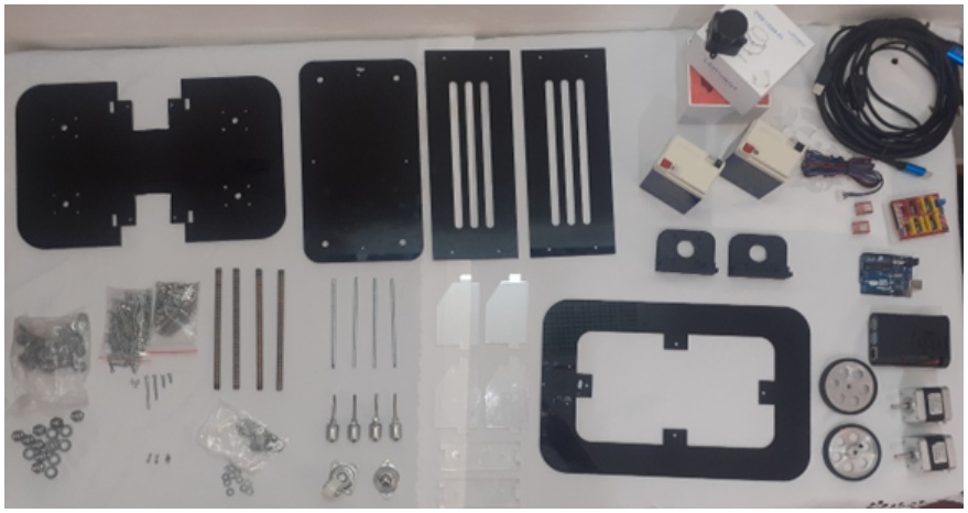
Figure 1.
Robot components used in the proposed mobile robot platform
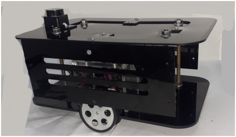
Figure 2.
Fully assembled differential-drive mobile robot system
3. Data Collection and Processing
In this section, a webcam was used to capture images for hand gesture recognition. Hand movement data was extracted using the MediaPipe library. For the predefined gestures shown in Figure 3, such as forward, backward, left, right, and stop, images and the corresponding hand key-point features were collected. Each gesture included a specific number of samples (in this case, 150 samples) recorded using the webcam and hand detection methods. After data collection, the data processing stage begins. The collected data consists of the coordinates of hand key points extracted by MediaPipe, along with labels corresponding to each gesture. These labels categorize the data into their respective classes, helping to define the meaning of each sample. The data is then transformed into a DataFrame, where each row represents a sample of hand movements and its associated features. This transformation is necessary to structure the data in a format that can be understood by the machine learning algorithm. During this stage, data quality is also assessed, and the accuracy of the labels is verified, as any errors in the data will directly lead to inaccuracies in the learning model.
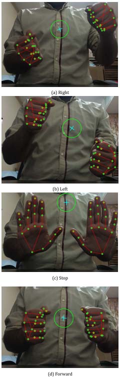
Figure 3.
Hand gestures for controlling the system: Right, Left, Stop, and Forward
To evaluate the data, a scatter plot is used. By placing data points in a two-dimensional space, the scatter plot allows researchers to observe the distribution of data and examine relationships between variables. It is an efficient tool for visualizing potential patterns, identifying anomalies, and detecting relationships between features and labels. In machine learning projects, examining data features through scatter plots helps researchers understand the distribution and correlation of features before proceeding with model development. This initial understanding of the data is crucial for building accurate and effective models. Figure 4 shows the scatter plot of the collected data.
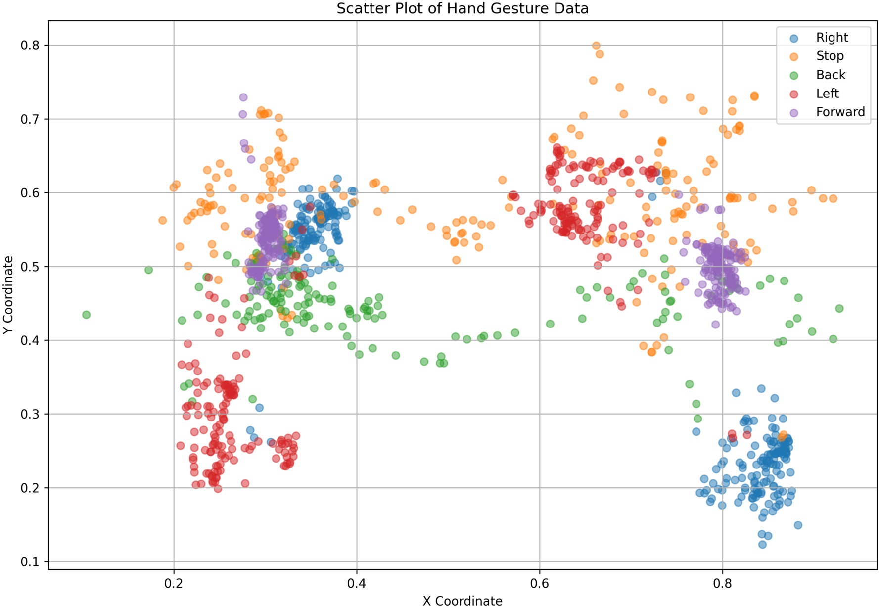
Figure 4.
Scatter plot of the data collected
4. Modeling and Training
After creating the Data Frame, the data is divided into three main sets:
- Training Set: Used to train the model.
- Validation Set: Used for tuning the model’s hyperparameters and preventing overfitting.
- Test Set: Used for the final evaluation of the model after training and validation.
The dataset was divided into training, validation, and test sets using a 60:20:20 ratio. It’s important to note that typically, data is split into two sets, training and test. However, this method may not provide an accurate assessment of the model’s performance. A separate validation set, containing data the model hasn’t seen before, offers a better evaluation of its accuracy. In this project, the train_test_split function from the sklearn library is used to split the data into specific proportions. This ensures that the label distribution is consistent across all three sets. The model used in this project is a Support Vector Machine (SVM), designed for hand movement classification. This model is trained using features extracted from the data. The training process includes utilizing the fit method for the SVM model with training data. The model’s hyperparameters, such as the kernel and the C parameter, are also tuned during this stage.
SVM has gained popularity due to its powerful data separation capabilities and effective performance, especially in high-dimensional datasets. SVM operates based on the concept of the maximum margin. The goal of this algorithm is to create a line (in two dimensions) or a hyperplane (in higher dimensions) that best separates the different data points. This hyperplane is selected in such a way that the distance between it and the closest data points, known as support vectors, is maximized. This feature enables SVM to generalize well to new data and prevents overfitting. SVM utilizes a kernel function to process data in higher dimensions. During the training phase, SVM computes the optimal hyperplane using labeled data. In the prediction phase, this hyperplane is used to classify new data. In addition to classification, SVM can also be applied to regression problems where the goal is to predict continuous values. In the present project, SVM is used to recognize hand movements and convert them into control commands for a robot. This algorithm accurately analyzes the data collected from hand movements, delivering precise results that are applied to control the robot in various environments.
5. Validation and Implementation
After training the model, its performance is evaluated on the validation set using the predict method. This method generates predicted labels for the validation data. For an initial assessment, the accuracy metric is used, which indicates the percentage of correct predictions. Accuracy is calculated using the accuracy score function. Although accuracy is an important metric, it is not sufficient on its own, especially when dealing with imbalanced data. To improve the evaluation of the model and to gain a better understanding of its performance across different categories, more advanced metrics such as the confusion matrix and F1-Score are used.
The confusion matrix is a key tool for evaluating classification models, allowing for a more precise examination of the model’s performance. This matrix is a square table where the rows represent the actual classes and the columns represent the predicted classes by the model. The confusion matrix includes four key pieces of information:
True Positive (TP): Samples correctly classified.
False Positive (FP): The number of samples incorrectly assigned to a class.
False Negative (FN): Samples wrongly classified into another category.
True Negative (TN): Samples correctly identified as belonging to other classes.
This matrix is particularly useful for analyzing the model’s errors. High FP or FN values in specific areas highlight the model’s weaknesses in classification. The confusion matrix is also used to compute important evaluation metrics such as Precision, Recall, and F1-Score, which provide a more detailed analysis of the model’s performance. For instance, if the model performs well in recognizing gestures like moving forward but struggles with identifying gestures such as turning left, these issues will be visible as FP or FN errors in the matrix. This powerful tool helps improve the model by allowing us to analyze its mistakes. In Figure 5, the confusion matrix of the collected data model is presented.
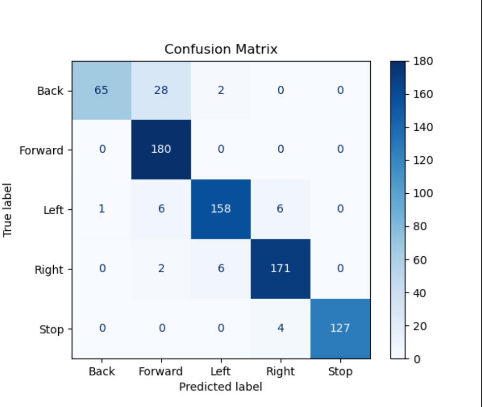
Figure 5.
Confusion matrix of the model
5.1. Model evaluation
The F1-score is a fundamental metric for evaluating the performance of classification models, particularly when the data is imbalanced or when both precision and recall are equally important. The F1-Score is the harmonic mean of Precision and Recall, ensuring that if either metric is low, the F1-Score also decreases. Precision indicates the percentage of instances correctly assigned to a specific class (of the predicted samples in that class, how many truly belong to it). Recall shows how many of the actual instances of a class were correctly identified by the model. These metrics together provide a comprehensive view of the model’s performance and help identify areas for improvement, particularly in imbalanced datasets.
The F1-Score is calculated using the following formula:
The F1-Score is particularly valuable in situations where both False Positive (FP) and False Negative (FN) errors are equally important. For instance, in a gesture recognition system, if the model incorrectly classifies the gesture ”turning left” as ”moving forward” (False Positive), or fails to correctly identify a ”turning left” gesture (False Negative), both errors can negatively affect the overall system performance. The F1-Score helps evaluate this balance, ensuring that the model not only has high precision but also maintains good recall. Therefore, the F1-Score is especially useful in scenarios where there is an imbalance in class distribution, or when both types of errors (FP and FN) are equally significant. This metric offers a more comprehensive view of the model’s performance, particularly when the focus is on balancing precision and recall, helping to identify and improve the model’s weaknesses. Table 1 presents the F1-score of the model.
5.2. Implementation and discussion
In the final stage, a ROS 2 node was developed to classify hand gestures and convert them into motion commands for the robot. This node uses the trained model to interpret user commands and execute the corresponding actions. The node uses the trained machine-learning model to classify hand gestures and enables the robot to respond to the corresponding commands. This process integrates image processing and machine learning technologies, combining precise gesture recognition with robot control. The node, referred to as ”Hand Gesture”, is developed in ROS 2 and its main function is to predict hand gestures through visual data captured by a webcam. It uses the MediaPipe library to process images and detect key points on the hands. MediaPipe automatically identifies critical hand landmarks (such as fingertips), and these points are passed as input features to the machine learning model.
Once the data is processed, the pre-trained machine learning model makes predictions based on the detected gestures. These predictions correspond to five main commands: ”Forward”, ”Back”, ”Left”, ”Right”, and ”Stop”. In the image processing workflow, video frames captured by the camera are first converted to RGB format and then analyzed. For each hand detected in the image, MediaPipe provides a set of key points, represented as (x, y) coordinates in the image space. Since hand gestures involve specific movements that alter the position of these hand points, this information is used effectively to identify different movement commands. This node simultaneously tracks both hands, crucial for simulating human-like natural robot movement (such as steering with two hands). After identifying the fingertips, the distance between them is calculated, and a large circle is drawn on the image as a ”steering wheel,” visually showing the user that the robot is receiving motion commands.
The machine learning model used is SVM, which acts as a classifier for predicting hand gestures based on extracted hand features. The training data used to build the model consists of features representing the position of various hand points, predicting whether a specific gesture like ”Forward” or ”Stop” is being performed. After training, the model is saved as a pickle file and loaded into the node. The model achieved a training accuracy of 0.9497, with both validation and test accuracies equal to 0.9286. It is important to note that since an SVC was used, the model performs global optimization over the entire dataset rather than using iterative updates as in neural networks. As a result, the number of epochs is not applicable in this context. Moreover, the internal loss function of the SVC is not accessible or stored during training, and therefore, it is not possible to report a loss curve or stage-wise average loss. As soon as new hand features are received, the model makes predictions that are converted into commands for the robot. The model automatically predicts one of the five commands, and based on these predictions, the robot’s linear and angular velocity is updated. For instance, the ”Forward” gesture increases the robot’s linear speed, while the ”Stop” gesture results in a full stop.
After the gestures are predicted, they are translated into motion commands for the robot. For example, the ”Forward” prediction increases the robot’s linear velocity, while the ”Left” or ”Right” predictions adjust its angular velocity. These commands are sent from the node through Twist messages, which set the robot’s linear (linear.x) and angular (angular.z) velocity values essential for movement. Finally, the robot can respond in real-time, moving according to the user’s hand movements. The node operates continuously, processing new frames and data and sending appropriate commands to the robot. Under the tested indoor lighting conditions, the system recognized the defined gestures at distances of up to 1.8 m. This means it works well in typical room lighting conditions and does not require special lighting or very close proximity to function effectively.
6. Conclusion
This paper has presented the design and implementation of a gesture-controlled differential-drive mobile robot utilizing the ROS 2 framework for gesture-based control in HRI. The integration of machine learning techniques, specifically through gesture recognition using the MediaPipe library, has enabled intuitive, real-time control of the robot without the need for physical interfaces. Through extensive testing, the proposed system has demonstrated its potential to enhance natural, non-invasive interactions in service robotics and collaborative environments. The use of ROS 2 not only provided a flexible and modular framework for developing the robotic system but also facilitated seamless real-time communication, crucial for effective HRI. This research contributes to the growing field of intuitive robot control systems, providing a robust foundation for future work. Potential areas for further development include optimizing the system for use in dynamic and complex environments, improving gesture recognition accuracy, and expanding its application to other HRI scenarios such as healthcare and industrial settings. The current implementation uses discrete gesture categories mapped to fixed motion commands, including predefined speed and turning angles. However, this could be extended in future work to incorporate gesture intensity or hand movement dynamics for variable-speed control. Additionally, a suggestion is made to integrate a steering wheel interface to improve ergonomics and realism, providing users with a more familiar and physically engaging control option.