

1. Introduction
The Robot Operating System (ROS) has served as the backbone for numerous robotics applications over the past decades. Although ROS 2 has introduced significant enhancements [1], such as distributed communication via Data Distribution Service (DDS) and improved real-time capabilities, its deployment on resource-constrained microcontrollers remains challenging. Prior work [2] demonstrated that the micro-ROS system can extend ROS 2 capabilities to devices with limited computational resources (e.g., ESP32). In this paper, we present the results of the research on the integration approach for mobile robots by porting micro-ROS to the TurtleBot3 platform on the OpenCR1.0 board [3] with ARM Cortex M7, including a floating-point unit (FPU).
Traditionally, TurtleBot3 architecture incorporates a Raspberry Pi to run ROS 2 nodes and an OpenCR1.0 board for low-level control of Dynamixel servos, and communication between these components is achieved using rosserial over a USB connection. However, this dual-controller scheme may increase architectural complexity and power consumption. Our objective is to consolidate control and communication functions on a single hardware platform, improving security, reducing power consumption, and simplifying the overall design while using the new software.
Here we propose an update to the general framework of the robot by the introduction of the microROS system, installing it directly onto the OpenCR1.0 board. The updated software stack introduces several key capabilities, including support for the DDS, a node-based modular architecture, and standardized communication interfaces. In our streamlined approach, the Raspberry Pi is removed entirely, with the ROS 2 node running directly on the microcontroller while simultaneously managing low-level control. Furthermore, to maintain the complete functionality of the initial system, wireless communication was implemented in two variants: first including Grove Bluetooth module and UART communication; second including Grove WiFi-UART module and UDP protocol.
2. TurtleBot3 Overview
The TurtleBot3 platform, developed by Robotis in collaboration with Open Robotics, represents a widely adopted standard for research and education in mobile robotics. Designed as a low-cost modular system compatible with ROS and ROS 2, it balances affordability with robust functionality, enabling applications ranging from autonomous navigation to human–robot interaction studies. Among its two primary variants: the Waffle, optimized for manipulation tasks with its broader chassis, and the Burger, a compact model prioritizing agility, this research focuses on the Burger variant (Figure 1). Its minimalist design reduces mechanical complexity while retaining core capabilities, making it an ideal candidate to evaluate embedded ROS 2 solutions.
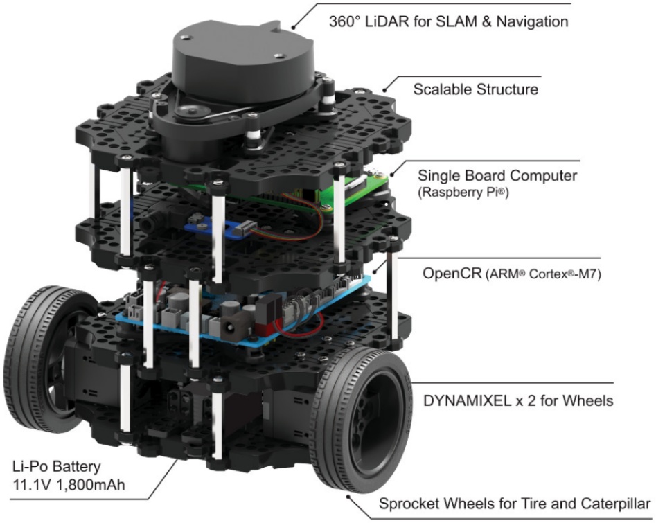
Figure 1.
TurtleBot3 general layout [3]
At its core, the TurtleBot3 Burger relies on a bifurcated architecture that segregates high-level computation from low-level control. The higher layer traditionally employs a single board computer (SBC), a Raspberry Pi (e.g., Pi 4), which hosts ROS 2 nodes for tasks such as simultaneous localization and mapping (SLAM), path planning, and sensor fusion. This subsystem runs on a Linux distribution and communicates with the actuators of the robot through a secondary microcontroller board, the OpenCR1.0. Beyond actuation, TurtleBot 3 is equipped with the platform sensing suite, including a LiDAR (LDS-01) for environmental mapping and a 9-axis inertial measurement unit (IMU) for orientation estimation. Communication between the SBC and the microcontroller occurs via serial communication using USB connectivity.
More resource-intensive tasks, such as RViz visualization, can instead be executed on a separate networked computer that also supports ROS communication.
3. OpenCR1.0 Microcontroller Board
The OpenCR1.0 (Figure 2), developed by Robotis, serves as a bridge between software abstraction and physical hardware. Built around an STM32F746NGH6U microcontroller (216 MHz ARM Cortex-M7 core, 1 MB Flash, 320 KB SRAM), it executes real-time control loops for the Dynamixel AX-12A smart servos that drive the robot wheels. These actuators integrate positional feedback via built-in encoders, enabling closed-loop control. Communication between OpenCR1.0 and Dynamixel servos occurs over a half-duplex TTL bus. Consequently, OpenCR1.0 serves as the embedded control center within the TurtleBot3 project.
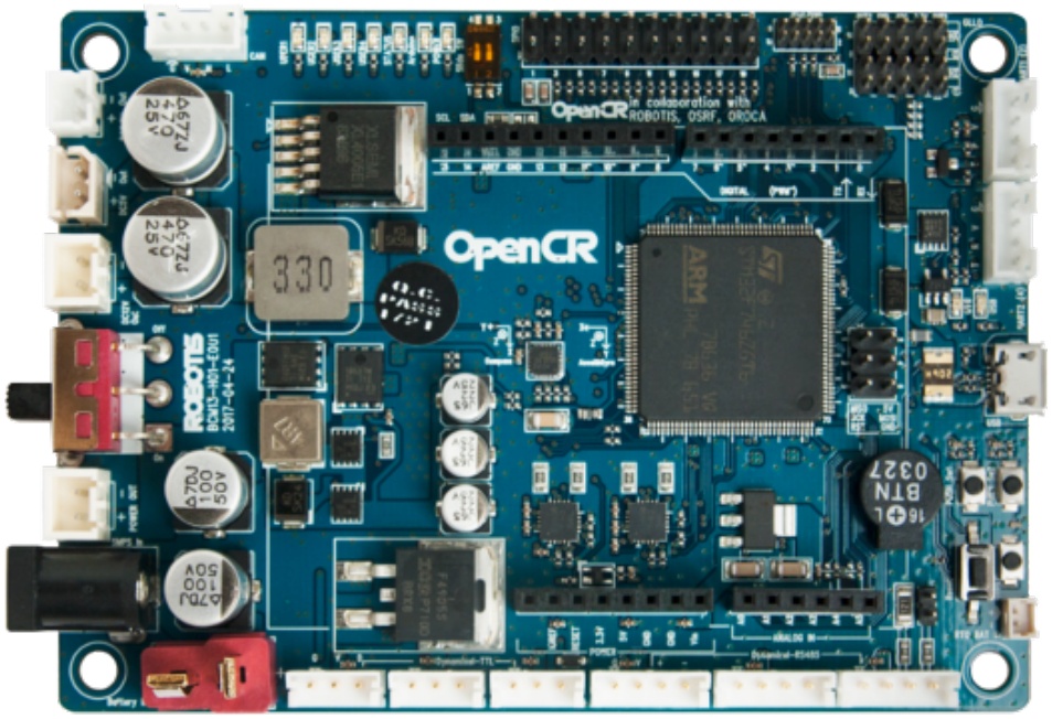
Figure 2.
OpenCR1.0 layout [3]
The microcontroller utilizes an Arduino-based framework through the Arduino IDE. This software provides dedicated libraries and allows for a simplified development process and rapid prototyping with easy firmware updates via a Device Firmware Upgrade (DFU). At its core, OpenCR1.0 interfaces with Dynamixel AX-12A servos through the dedicated Dynamixel2Arduino library of Robotis, which abstracts the complexities of the Dynamixel TTL communication protocol (Protocol 2.0). This library provides methods for configuring servo parameters (e.g. operating modes, velocity limits), reading positional feedback from built-in encoders, and executing synchronized motion commands. For instance, wheel velocity control is achieved by converting ROS geometry_msgs/Twist messages into Dynamixel-specific angular velocity targets, leveraging the function of the provided library. The OpenCR1.0 firmware parses incoming Twist commands from the Raspberry Pi into Dynamixel actuator instructions while simultaneously aggregating sensor data (e.g., IMU readings, wheel odometry) into ROS sensor_msgs and nav_msgs formats for upstream processing.
However, this architecture imposes inherent constraints: Rosserial lacks native support for ROS 2 Quality of Service (QoS) policies, and its serialization/de-serialization routines introduce latency during high-frequency data exchanges.
4. RPi Based Architecture
In the default configuration, a Raspberry Pi communicates with an OpenCR 1.0 board using Rosserial [4], a legacy protocol inherited from ROS 1. Operating over a USB–UART connection, Rosserial converts ROS messages into a serialized byte stream with a custom protocol, establishing a client–server communication model. Messages from the standard ROS network are serialized and transmitted via a serial link to a Rosserial client using the defined packet format; the reverse process occurs when data from the microcontroller are sent to the Rosserial server. The protocol implements custom methods for data negotiation to determine publish–subscribe pairs by querying embedded devices for necessary information such as topic names, message types, and other metadata. In the Rosserial frame structure, a typical message begins with a synchronization flag, followed by protocol version information, a payload length indicator, and then additional fields such as CRC length, topic ID, serialized payload, and finally CRC message. Furthermore, time synchronization between devices is achieved by transmitting std_msgs::Time messages and applying the necessary clock offset.
Although functional, the protocol has several drawbacks that could limit its usage. For example, it lacks native compatibility with ROS 2, which introduces significant challenges when attempting to integrate legacy systems with the modern ROS 2 ecosystem. The architectural changes in ROS 2, such as the introduction of DDS-based communication and enhanced security features, render Rosserial less adaptable.
For instance, the adopted standard for microcontroller interfacing with ROS 2 is the eProsima Micro XRCE-DDS allowing for communication eXtremely Resource Constrained Environments (XRCEs) with the DDS framework. A detailed comparison with Micro XRCE-DDS reveals some of the inherent shortcomings of Rosserial.
Although rosserial lacks standardized framing techniques, Micro XRCE-DDS over serial transport employs HDLC framing, providing a more defined and reliable structure. In Rosserial, the CRC used for message verification is based on a simplistic modulo 256 calculation, which is less rigorous compared to the CRC-16-CCITT standard adopted by Micro XRCE-DDS. These differences reflect a larger issue: Rosserial error-checking and data integrity measures are not as robust, leaving room for potential reliability issues in more demanding applications.
Memory usage is another area where Rosserial shows limitations. The serialization process in Rosserial requires the hardware buffer to be as large as the serialization buffer, leading to potentially higher memory overhead. In contrast, Micro XRCE-DDS makes use of a more efficient buffer management strategy, reducing memory consumption by decoupling the size of the hardware buffer from that of the serialization buffer. This not only optimizes resource usage, but also allows for larger message sizes dictated by the uxr_stream rather than the physical limitations of the hardware buffer [5].
5. Researched Micro-ROS Based Architecture
The micro-ROS system extends the core concepts of ROS 2 to resource-constrained devices by introducing its lightweight but fully compatible implementation. It utilizes a layered architecture that reuses many of the foundational components of ROS 2, ensuring consistency in node design, communication protocols, lifecycle management, and system interoperability. The following points summarize the key aspects of micro-ROS:
- Resource-Constrained Adaptation: Unlike traditional ROS 2 implementations that require significant computational resources, micro-ROS is specifically tailored for microcontrollers and embedded systems. It achieves this by employing a design that minimizes dynamic memory allocation after the initialization phase, thereby ensuring efficient and deterministic operation in real-time environments.
- Distributed and Modular Design: micro-ROS embraces a decentralized architecture of the traditional ROS 2 system. Using the discovery system, the nodes broadcast their presence via the DDS API, allowing a modular fault-tolerant system where each component can operate independently.
- Middleware Integration: At its core, micro-ROS uses Micro XRCE-DDS middleware to interface with DDS communication [6]. This middleware layer enables micro-ROS to adopt the DDS communication model, including support for publish–subscribe and client–service interactions. However, discovery processes (node broadcasting its presence via the DDS API) and Quality of Service (QoS) mechanisms are offloaded by the ROS Agent, as they would be too computationally expansive for an embedded device. As such, the ROS Agent is expected to run on a host capable of running standard ROS 2 application.
- Lightweight Abstraction Layers: To bridge the gap between resource-limited devices and the full-fledged ROS 2 ecosystem, micro-ROS introduces the RCLC library, a compact C API that mirrors the functionality of the more comprehensive RCLCPP. This enables developers to implement executors, manage node lifecycles, and schedule callbacks with minimal overhead.
The architectural design of micro-ROS not only preserves the familiar concepts of ROS 2 but also introduces innovations that make it suitable for embedded systems, as seen in the architecture layout in the Figure 3. This balance of compatibility and optimization supports diverse robotic uses, ranging from small-scale sensors to mobile platforms, effectively bridging the gap between high-level robotics frameworks and low-level hardware constraints.
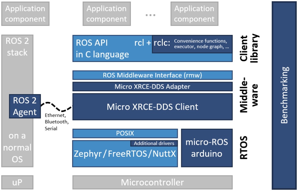
Figure 3.
Architecture of the micro-ROS stack [7]
However, when using micro-ROS, the microcontroller is always the client within the network, while the host role is taken by the ROS Agent. It imposes some limitations on system usage; it is particularly impossible for the microcontroller to use ROS 2 software to communicate directly with another MCU through peer-to-peer architecture.
6. Proposed Architecture
The proposed architecture (Figure 4) eliminates the necessity of the Raspberry Pi SBC by embedding complete ROS specific components directly on the OpenCR1.0 board. For that, the micro-ROS software was installed on the existing OpenCR1.0 board and combined with the already present software for low-level control, together fulfilling application needs as a sole hardware component. The OpenCR1.0 board falls within the scope of micro-ROS supported devices [7], with the restriction of official support limited to Arduino framework with serial communication protocol for interfacing with the ROS Agent. Since the board lacks the ability for wireless communication, it was complemented with the necessary modules in two variants: One with the Grove series Bluetooth v3; Second with Grove UART Wifi V2.
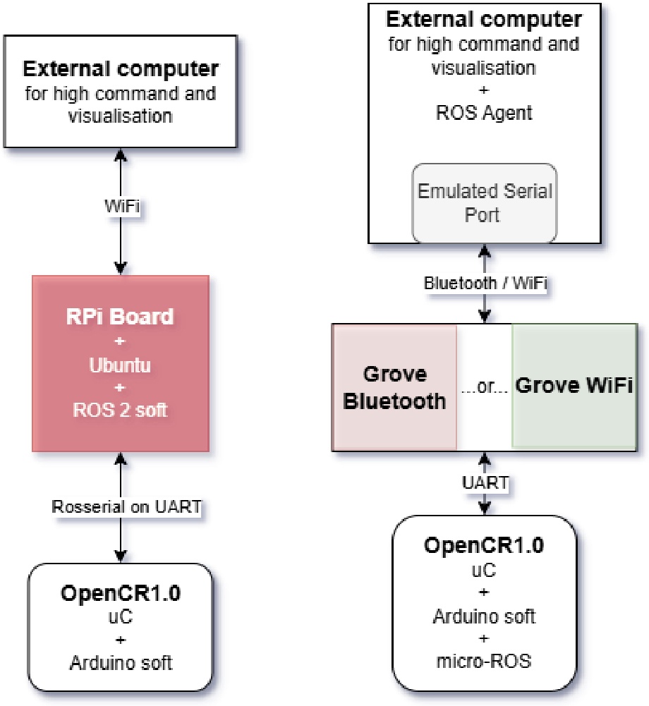
Figure 4.
Original architecture compared to proposed one
Each module enables the transmission of serial data by connecting it to the RX/TX pins of the microcontroller (Serial 1), passing the data wirelessly via Bluetooth or WiFi, thus enabling message exchange with the ROS 2 application running on a host system.
For the Bluetooth variant, the host system was paired using the rfcomm [8] utility. This involved binding the module MAC address to a virtual serial port (e.g., /dev/rfcomm0, listing 1), enabling the ROS Agent to interact with the device as a standard serial interface. On the microcontroller side, the Bluetooth module was pre-configured via AT commands to operate at a baud rate of 115200 bps, with persistent settings for device visibility and pairing mode. For ROS integration, the micro-ROS agent was initialized with the designated virtual port, treating the Bluetooth link as a conventional serial channel for publishing sensor data and subscribing to control topics.
Following the Bluetooth setup, interchangeable steps can be prepared for the WiFi variant. The Grove UART WiFi V2 module was configured through AT commands executed during microcontroller initialization. The configuration sequence set the module to station mode, established persistent WiFi credentials, verified network parameters, and initiated UDP connectivity to a designated host IP and port. Crucially, transparent transmission mode was enabled to allow continuous data streaming. On the host system, the socat utility bridged the UDP packets to a virtual serial interface (e.g., /dev/ttyWiFi, listing 1), which served as the communication endpoint for the ROS system. The ROS Agent was subsequently launched against this virtual port at 115200 bps, identical to the Bluetooth configuration, ensuring consistent ROS API exposure regardless of the underlying wireless technology.
Listing 1. Binding connection to virtual serial port
rfcomm connect /dev/rfcomm0 <MAC> # Bluetooth
socat -d -d PTY,raw,echo=0,link=/dev/ttyWiFi UDP6-LISTEN:8888,reuseaddr # WiFi
Although the micro-ROS Agent natively supports UDP transport, the official OpenCR1.0 micro-ROS client distribution is provided and tested for serial transport only. To use an IP-based link (WiFi/UDP) from the OpenCR board, we implemented a custom transport that carries the Micro XRCE-DDS wire protocol over an ESP-AT based WiFi module. The micro-ROS middleware allows for interfacing with the lowest-level transport layer at runtime, essentially making the Micro XRCE-DDS wire protocol transmittable over any communication mechanism. As such, a custom transportation can be tailored specifically for our use case. Following the official guide [9], it is required to implement external transport callbacks as in the listing 2 in the form of functions for opening, closing, reading from, and writing to the custom link.
Integration was made by reusing the upstream official micro-ROS Arduino codebase [10], where WiFi specific code was provided. The repository has compatibility with ESP-AT modules upon defining the BOARD_WITH_ESP_AT macro. Our Grove UART WiFi V2 module falls into this category, as it is configured via AT commands over a serial interface. This code utilizes an underlying library to manage the WiFi module via AT commands, establishing a UDP client that connects to the IP address and port of the host running the micro-ROS agent. Consequently, the agent can be launched in UDP mode, allowing the OpenCR1.0 board to communicate directly over WiFi without an intermediate serial-to-UART bridge.
Listing 2. Custom transport definition
rmw_uros_set_custom_transport(
false , // Framing disabled here
(void *) &locator ,
arduino_wifi_transport_open ,
arduino_wifi_transport_close ,
arduino_wifi_transport_write ,
arduino_wifi_transport_read
);
7. Environment Setup
With Arduino as the main framework of the board, the entirety of the application was hosted and built using the PlatformIO IDE solution for VS Code, enabling easier dependency management with support for micro-ROS libraries. As OpenCR 1.0 is not officially supported by PlatformIO, we applied a set of community-contributed patches following the approach described in the Dragonbot blog [11]. This required manually creating package metadata files in PlatformIO directories to register the modifications. After applying these changes, PlatformIO recognizes OpenCR as a board, meaning projects targeting OpenCR could be initialized and built using platformio init –b opencr commands.
The listing 3 directs PlatformIO to use the patched STM32 platform with OpenCR board metadata, including the Arduino core. The lib_deps entries explicitly reference both the micro-ROS PlatformIO integration and the Dynamixel2Arduino library, ensuring hardware-specific servo control capabilities. Enabling deep+ library resolution ensures that nested includes from micro-ROS are discovered correctly. Specifying the micro-ROS distribution as Humble aligns the firmware expectations with the host-side packages and tools; in practice, this setting propagates into build scripts so the correct client libraries and settings are selected for Humble, which is a recommended ROS 2 release. By default, the transport of micro-ROS is set to serial and can be switched to a custom one that enables a UDP connection via the WiFi module. Furthermore, with the board framework using its own boot loader called opencr_ld, the upload command needs to be customized by directly invoking the OpenCR tool rather than a generic STM32 programmer.
Listing 3. Example configuration in platformio.ini file
[env:opencr]
platform = ststm32
board = opencr
framework = arduino
lib_deps =
robotis-git/Dynamixel2Arduino @ ~0.7.0
jandrassy/WiFiEspAT@^2.0.0
lib_ldf_mode = deep+
board_microros_distro = humble
board_microros_transport = custom
On the host side (a personal computer, e.g., RPi SBC), the application setup for communication with the micro-ROS is resolved with Docker images [12]. Firstly, for interfacing with the microcontroller, a ROS Agent needs to be present; as such, running the command with the specified serial port (or UDP mode with the port number) is enough to have a functional application. Secondly, to run ROS 2 applications on the TurtleBot3, a container with installed ROS 2 dependencies was prepared, along with packages providing functionalities for common messages, visualization, and a teleoperation interface.
8. Application Development
Application development starts with mirroring the code of the TurtleBot3 repository to have the original codebase as a baseline. The first task is to identify and remove all code, libraries, and configuration tied to rosserial-based communication while preserving the core control loops and the low-level hardware abstraction (motor drivers, sensor reads, IMU handling, and encoder processing). Once the Rosserial references are stripped out, the remaining code is organized into clear modules:
- Hardware Abstraction Module: contains low-level drivers for Dynamixel servos, IMU, encoders, and any serial peripherals (e.g., Bluetooth/WiFi module). These routines expose simple C/C++ functions for reading sensors and commanding motors.
- micro-ROS Client Module: encapsulates initialization of the micro-ROS node, RCLC support setup, allocator configuration, publishers/subscribers, timers, and executors. This module handles all interactions with the ROS Agent via XRCE-DDS over the chosen serial transport.
- Control Logic Module: implements control loops (e.g., odometry calculations, goal-velocity updates, safety checks), which invoke hardware abstraction functions and publish sensor data or act on incoming commands.
- Connectivity and Diagnostics Module: manages transport setup, monitors ROS Agent connectivity, handles reconnection logic, and manages LED/error indicators for status feedback.
After organizing into the four modules, we proceed with incremental integration. First, hardware abstraction is verified standalone. Then, we embed the micro-ROS setup in a compact initialization function. Listing 4 shows a minimal publisher that replaces Rosserial communication:
Listing 4. Example of micro-ROS publisher definition
RCCHECK(rclc_publisher_init_best_effort(
&publisher_sensor_state ,
&node,
ROSIDL_GET_MSG_TYPE_SUPPORT(
turtlebot3_msgs , msg, SensorState),
"sensor_state"));
In order to address bottlenecks, the communication type was configured to a predefined setting of best_effort. This guaranties the delivery of the most up-to-date data and avoids the retransmission mechanics that could impose a significant strain on the network, particularly under unstable conditions.
The control loops were resolved using RCLC timers paired with dedicated publishers, enabling scheduled publications on different types of topics (listing 5). Timers need to be assigned to the executor; then, an executor needs to have a specified number of handlers for proper initialization: Each timer or subscription added will increment this number. In our case, we grouped publishing timers into one executor and created another executor dedicated to subscription handling; Thus, we minimize callback interference with more consistent loop timing and guaranty easier scalability.
Listing 5. Example timer definition with executor initialization
RCCHECK(rclc_timer_init_default(
&timer_drive_info ,
&support ,
RCL_MS_TO_NS(1000 / PUBLISH_FREQUENCY),
publishDriveInformationCallback));
RCCHECK(rclc_executor_init(&executor , & support.context , 3, &allocator));
RCCHECK(rclc_executor_add_timer(&executor , &timer_drive_info));
To maintain a common interface of messages native to the TurtleBot3, a package containing their definitions is required to be present at build time.
Because micro-ROS rebuilds message interfaces through its own framework, the TurtleBot3 message package had to be included in the workspace before building. To automate this, custom or vendor-specific packages can be placed inside extra_packages directory at the repository root, either by adding them directly or by creating an extra_packages.repos file with entries pointing to their GitHub repository URLs. During the build, the micro-ROS setup fetched and compiled these definitions so that the common TurtleBot3 interfaces were maintained seamlessly.
As of today, microROS does not fully support the standard transformation package, which is called the TF2 – its usage is limited to the underlying tf2_msgs and elementary math utilities, assuming their placement in extra_packages directory. To work around this, one can implement transform broadcasting manually: instantiate a TransformStamped message, populate its header (stamp, frame IDs) and transform fields (translation and quaternion), then publish it on the /tf topic at the desired rate. In practice, this means creating a dedicated micro⍰ROS publisher and timer callback that periodically fills out and emits the TransformStamped message, replicating the behavior of TransformBroadcaster without requiring the full TF2 library.
The connection to the ROS Agent was confirmed via the built-in rmw_uros_ping_agent command, which allowed the application setup to block until the agent responded. If the ping fails, the system automatically retries and waits, resuming initialization as soon as the agent is reachable. Finally, the connection with the ROS Agent was complemented with calls to the rmw_uros_sync_session function, enabling time synchronization between devices using built-in tooling.
9. Experimental Results
The application assumes an active connection to the TurtleBot 3 ecosystem. In addition to running the ROS Agent and the robot itself, we leveraged key components of the TurtleBot 3 software stack, such as RViz visualization, the robot description package, teleoperation modules, and other related packages for seamless compatibility.
Using the ros2 launch turtlebot3_bringup rviz2.launch.py we start all core TurtleBot 3 drivers, TF broadcasters, and the RViz visualization. Next, in another terminal, we run ros2 run turtlesim turtle_teleop_key with the proper topic remap to send keyboard commands to the /cmd_vel topic. Each key press is picked up by the robot’s micro⍰ROS subscriber, translated by the hardware abstraction layer into Dynamixel servo instructions, and executed by the motors. The robot successfully reads and processes the message and sends back all the required data, including the odometry and sensory information. Figure 5 shows the output of the RViz tool, in which the odometry of the moving robot is displayed, reconstructing the robot trajectory relative to its starting pose.
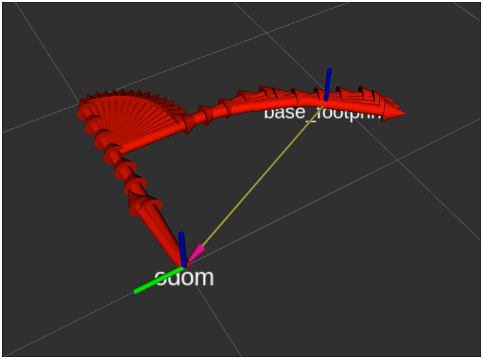
Figure 5.
Visualized odometry of robot moving within 1x1m square
For an experiment, we quantified the end-to-end transport delay using the built-in CLI utility ros2 topic delay. This tool subscribes to a topic and computes the time difference between each message header/stamp and the host reception time. With enough message count, the statistics are provided as follows: minimum, maximum, mean, and standard deviation, presenting a compact view of latency and jitter without custom parsing. Because accurate one-way measurements require synchronized clocks, the micro-ROS client was configured to perform time synchronization with the ROS Agent (via the rmw_uros_sync_session calls), so header/stamp values emitted on the OpenCR1.0 are directly comparable to host timestamps. While the TurtleBot3 runs the full set of topics and TF broadcasters (each with best_effort QoS policy), we deliberately selected a single representative telemetry stream for the transport comparison. The tested topic is /sensor_state (turtlebot3_msgs/SensorState), a custom message that aggregates multiple sensor readings and status fields into a single payload; because it contains many fields, it provides a realistic measure of both serialization overhead and network behavior for typical robot telemetry. For the experiments, this topic publish rate was set at 10 Hz, with the window of 10 000 samples. The test was prepared for every variant of the application:
- custom micro-ROS transport with WiFi module and direct UDP protocol,
- serial micro-ROS transport with WiFi module and Socat mapping of UDP to virtual serial port,
- serial micro-ROS transport with Bluetooth module and rfcomm mapping to virtual serial port.
Each configuration was evaluated in two variants: first, via direct topic analysis, and then with a constant 30 Hz background input stream published to the robot /cmd_vel topic to emulate a sustained teleoperation load and observe its effect on latency and jitter.
The results (Table 1) show that native UDP transport yields the lowest mean latency and the tightest dispersion in our setup, whereas the Socat based WiFi bridge introduces substantially higher and more variable delays.
Table 1.
One-way latency statistics for /sensor_state (times in milliseconds)
| Test (ms) | Mean | Min | Max | Std |
|---|---|---|---|---|
| UDP | 16 | 14 | 37 | 1.72 |
| UDP + input | 28 | 14 | 114 | 15.60 |
| UDP (Socat) | 90 | 72 | 284 | 32.53 |
| UDP (Socat) + input | 80 | 76 | 225 | 9.50 |
| Bluetooth | 78 | 32 | 169 | 20.39 |
| Bluetooth + input | 123 | 41 | 256 | 35.14 |
Bluetooth results lie between the two, with moderate baseline latency but greater sensitivity to conditions. Introducing a constant 30 Hz command stream increased mean latency and jitter on multiple transports, indicating that link contention and bridging/buffering behavior materially affect end-to-end timing by prioritizing the input stream. Interestingly, the Socat bridge showed slightly lower latency under additional load, likely due to buffering and flushing effects in the pseudo-terminal mapping rather than a genuine transport improvement.
10. Comparison with Original TurtleBot3 Layout
To quantify the effect of reintroducing the Raspberry Pi, we set up a hybrid configuration: the OpenCR1.0 board still runs the identical micro-ROS application but now communicates over USB serial to a Raspberry Pi 4, which hosts the ROS Agent. The RPi is connected via WiFi to the host PC running RViz and diagnostic tools. This mimics the original TurtleBot3 split architecture (with micro-ROS instead of rosserial) and allows us to directly compare performance against the single-board design. In this setup, the micro-ROS node on OpenCR1.0 and the ROS Agent on the RPi form a chained data path, so messages from the MCU must traverse the USB link to the RPi, and then the wireless network to the host.
Accurate time synchronization across all devices is critical for valid latency measurements. We configured the host PC as an NTP time server (Chrony [13]) and the Raspberry Pi as its client. On the host, we added a network-wide allow rule in /etc/chrony/chrony.conf; on the Pi, we added server <host_ip> iburst and restarted Chrony on both machines. This ensures the RPi’s clock tracks the host’s clock. Concurrently, the OpenCR1.0 microcontroller uses the built-in time-sync mechanism of micro-ROS (rmw_uros_sync_session) to align its timestamps with the ROS Agent. With these steps, all components share a common time base, and the topic delay utility can yield accurate one-way latency values.
We then repeated the latency experiment exactly as before. The OpenCR1.0 micro-ROS node publishes the /sensor_state topic at 10 Hz. On the host PC, we ran the topic delay command to measure one-way message latency. Tests were performed both under idle conditions and with a sustained 30 Hz command stream on /cmd_vel to simulate high-load operation.
All timestamps originate from the MCU micro-ROS publisher, and due to our synchronization setup, the experimental results directly reflect the true transit time. We obtained latency statistics suitable for direct comparison by collecting the same number of samples as in the previous experiment.
Analyzing the results (Table 2), the single-board OpenCR1.0 with native UDP transport achieves more consistent low-latency behavior and avoids OS-induced spikes, supporting the claim that removing the Raspberry Pi simplifies the architecture and improves determinism. The RPi intermediary shows competitive or better average latency under load (because it can absorb bursts); however, the worst response time is significantly larger.
Table 2.
One-way latency statistics for RPi intermediary vs. best uC standalone (times in milliseconds)
| Test (ms) | Mean | Min | Max | Std |
|---|---|---|---|---|
| RPi | 14 | 6 | 415 | 16.03 |
| RPi + input | 18 | 13 | 334 | 3.86 |
| μC UDP | 16 | 14 | 37 | 1.72 |
| uC UDP + input | 28 | 14 | 114 | 15.60 |
In addition to communication performance and system complexity, power consumption plays a critical role in mobile robotics. To quantify the impact of the architectural simplification, we conducted direct power measurements of both configurations under typical runtime conditions, as presented in Table 3. Energy measurements made with a USB power tester show that the OpenCR1.0 + UART-WiFi configuration draws, on average, 1.19 W (≈237 mA at 5 V), whereas the OpenCR1.0 with a Raspberry Pi 4 intermediary draws 3.77 W (≈754 mA at 5 V). This corresponds to an ≈68.6% reduction in average power when the Raspberry Pi is removed, saving about 2.58 Wh per hour. Taken together, these results show that the single-board OpenCR 1.0, with a native UDP design driven by the micro-ROS framework, is a viable alternative to the RPi intermediary.
11. Conclusion
This study demonstrates that micro⍰ROS can be effectively ported onto the TurtleBot3 OpenCR1.0 board, enabling the consolidation of processing and control into a single embedded system. The resulting architecture reduces system complexity, power consumption, and preserves the performance expected from a ROS 2⍰based platform.
Our transport experiments between application variants indicate that native UDP provides the best latency characteristics for time-sensitive telemetry, while serial bridges (Bluetooth or socat-based WiFi) introduce larger and more variable delays that should be considered when designing control loops. Furthermore, Bluetooth typically consumes less power and is easy to set up for short-range, low-bandwidth control links. However, it has a limited range and throughput, and it can perform poorly in noisy RF environments. Compared to Bluetooth, WiFi offers substantially higher throughput, longer range, and stronger standardized security (WPA2/WPA3), making it better for high-rate telemetry and remote operation, at the expense of more complex configuration.
Future research will further investigate the scalability of this approach, with particular emphasis on communication robustness and the integration of additional microcontrollers for extended functionality. With reliable low-latency links and additional sensors, the platform can naturally support higher-level functionalities, such as map-based goal sending and local obstacle handling.