

1. Introduction
Electricity is important to improve people’s living standards. Without electricity we cannot imagine life. It plays an important role in enhancing the economy of any country [1]. Fossil fuels are available all the time and most generation plants use it for the generation of electrical power. Since the sources of fossil fuels are limited and emit toxic gases in the environment, it is required to use substitutes [2]. Now we can focus on renewable energy sources that are environmentally friendly and fulfill the demands of the people. A wind energy conversion system is the best substitute for classical fossil fuel generation plants.
Wind power plants have one major problem: The airflow is not constant. Due to such changes in airflow, transients arise in wind generators. These transients induced many power quality issues in the generated power. Transients can affect the reactive power, frequency, and voltage profiles. Control of the transient operation of a wind power plant with a doubly-fed induction generator using PI controller is implemented in this work. For accurate control of the DFIG generator gain, the PI controller is tuned using a hybrid optimization technique. The DFIG is a type of electrical generator used in wind turbines to generate renewable electrical energy [6]. DFIG wind energy conversion system is shown in Figure 1. For stability of operation and control of active and reactive power, the stator and rotor currents of DFIG must be controlled.
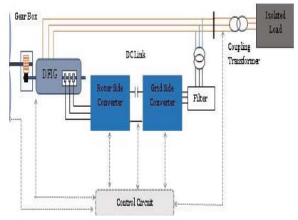
Figure 1.
Schematic diagram of the DFIG-WECS
The main objective of this work is to improve the transient response of the DFIG-WECS. For this purpose, a PI controller is mathematically modeled. After that, the goal is to find the optimized tuning of PI controller parameters used to control the operation of DFIG-WECS. A novel modified hybrid (Gray Wolf and Cuckoo Search) algorithm is used to find out optimal values of the PI controller gain parameters (Kp and Ki). The output results of the DFIG are verified by comparing the results in terms of THD values. The unique approach of this suggested work is the use of the modified hybrid algorithm which has never been suggested by the any other researcher for DFIG operation and control.
In the first section of the paper, an introduction to the current scenario of renewable and wind power generation is given, and it is explained that DFIG-WECS are a very important part of the wind power system. Section 2 presents the literature review and existing research in this field and discusses the research gap. The mathematical modeling of DFIG and its controller design are explained in Section 3 of the paper. In the subsection of this section, the vector-oriented control strategy is applied to the design of a rotor-side controller. The MGWOCS optimization method was developed by proposing small modifications to the hybrid methods of the Cuckoo search algorithm and the Gray Wolf algorithm describe in Section 4. In the Section 5, the implementation of MGWOCS in an experimental model is explained. In the same section, we implemented simulation of Jaya optimization, MGWOCS method, and the Whale optimization method for tuning of PI controller parameters. The results of the proposed experimental model are obtained in terms of graph and numeric values and listed comparatively for results of the Jaya optimization and Whale optimization algorithm. The final section of the paper draws conclusions from the research work.
2. Related Work
Vector and direct control methods are suggested for the stable operation of the DFIG system. Such control schemes are good but fail when loads are increased [1]. Wind conversion system with maximum power point tracking to enhance the harvest of wind generation is suggested in article [2]. MPPT moves the position of the head of the generator in the direction of the flow of air, and hence the rotor of the wind generator maintains good speed and generates high power [2]. The slip power recovery control technique used in article [3]. They used a power converter attached to the rotor windings to recover part of the slip power The productivity of the entire system can be improved by feeding this recovered energy back into the grid.
Pitch control in turbines refers to changing the angle of the turbine blades to regulate the aerodynamic load on the rotor. This helps to prevent over speeding and overloading of the generator in high wind flow conditions [4]. The DFIG’s power converter enables precise control of active and reactive power. This is crucial for grid integration and stability, as the generator can respond to grid demands and support voltage regulation [5].
The power converter of the DFIG can regulate the terminal voltage of the generator and thus ensure that it remains within the permissible limits even under changing operating conditions. In the event of short-term faults, DFIG systems must maintain the grid connection and continue operation [6]. In many cases, DFIG systems must remain connected to the grid in order to operate during short-term grid faults [7]. Modern control techniques allow the generator to withstand these faults without shutting down. By limiting the maximum permissible rotor current [8], the control system can prevent overloading and overheating of the rotor and associated power electronics. These techniques are often implemented with advanced control algorithms and real-time monitoring systems to ensure optimal performance, grid stability, and efficient energy conversion in DFIG-WECS [9].
The optimal design of proportional-integral-derivative (PID) controllers for DFIG wind generators is suggested in article [10]. They control the DFIG-based wind generators with a grid interconnection system. The fundamental principles of PID control, which include proportional, integral, and derivative components, form the basis for developing effective controllers for DFIG wind generators used by [11]. Researchers have explored various tuning methods to optimize PID parameters. Classical approaches such as Ziegler-Nichols [12] and Internal Model Control (IMC) [13] have been adapted and extended for DFIG applications.
More recent studies have explored advanced optimization techniques and adaptive strategies for tuning the PI controller in DFIG wind generators. Metaheuristic algorithms, such as particle swarm optimization [14], genetic algorithms [15], and artificial bee colony [16], have been employed to search for optimal PI parameter sets that balance stability, performance, and energy capture.
In addition, adaptive PI control strategies that adjust controller gains in real time based on system dynamics have shown better transient response and higher robustness. The integration of advanced control methods with PI controllers has shown promise in improving the overall performance of DFIG wind generators [17]. Fuzzy logic, artificial neural networks, and model predictive controllers (MPC) have been combined with PI strategies to improve fault tolerance, power tracking, and grid synchronization [18]. These hybrid approaches leverage the strengths of multiple techniques to overcome complex challenges.
The study of the transient behavior of DFIG, which includes faults in DC links, converters, rotor terminals, and other forms of stator terminal faults, such as phase-to-phase and phase-to-ground, is still lacking in the literature. However, these studies are only able to investigate and analyze the response of DFIG in three-phase short circuits. There is still a lack of research on the optimal design of regulators. To fill this gap, swarm intelligence is used in this proposed study, namely the modified Gray Wolf Optimization (GWO) method. The aim of this work is to design an optimal controller for DFIG-WECS. A novel modified hybrid Gray Wolf Cuckoo search algorithm is proposed and applied for obtaining the optimum parameters of the PI controller. To the best of the author’s knowledge, this optimization method has never been applied to DFIG-WECS in the past.
3. Mathematical Modeling
Mathematical modeling of the DFIG using the direct-quadrature (d-q) transform is a fundamental step in the development of the controller to control the transient behavior of DFIG systems [19]. The d-q transform, often referred to as the Park transform, provides a powerful mathematical tool to simplify the analysis of three-phase system as shown in figure 2.
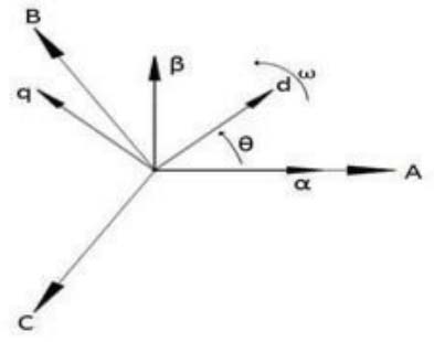
Figure 2.
Three-dimensional positioning of the vectors
The d-q transformation comprises two orthogonal components: The direct (d-axis), which is connected to the rotor flow, and the quadrature (q-axis), which is orthogonal to the d-axis. The three-dimensional distribution of the dq-transformation is explained in mathematical equations as follows [20]
Flux linkages for stator and rotor in d-q frame are given as:
In the above equations, Vqs, Vds, Vqr, Vdr, iqs, ids, iqr, idr, λqs, λqr, λqr, λdr, λds are the stator and rotor emf, currents, and the flux-linkages respectively, rs and rr denote resistance, Ls, Lr, self-inductance of stator and rotor windings, Lm, is the mutual-inductance and ωs, ωr are the synchronous and rotor angular speed.
The active, reactive power, and torque in the d-q frame in mathematical form can be written as:
In above equations “*” denotes the complex conjugate of quantity.
3.1. Controller designing using Vector Control Strategy
The vector-oriented control strategy was used for the design of a rotor-side controller [21]. The basic equations of current, flux and Emf of DFIG is given by assuming a reference frame connected to the stator flux (i.e. λds = λs, λqs = 0).
Equations (1) to (4) can be modified as follows (assuming stator resistance is negligible, and stator flux linkage is constant ( ),)
Real and reactive powers and electromagnetic torque is given as:
Where,
In Equations (20) and (21), by putting
Then we get,
by solving equations (27) and (28), we get:Gain for the current control is given by
Equation (27) and (28) is shown in Figure 3. The modified system is given in Figure 4 for the d-q axis.
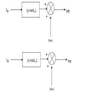
Figure 3.
Depiction of the relationship between voltage and rotor current in d-q frame
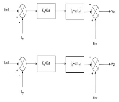
Figure 4.
Modified system after adding PI block in the d-q System
After adding PI controller, the governing equations are as follows.
So, the transfer function of current controller is,
A closed-loop feedback PI controller with the current control system is shown in Figure 5 and the proposed control system is sustainable energy grids and networks shown in Figure 6.
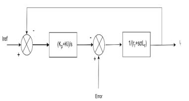
Figure 5.
PI current control system using close loop feedback system
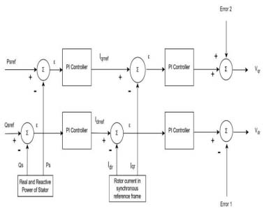
Figure 6.
Block diagram of RSC controller
4. Optimization Techniques
This article implemented a new technique, which is a modification of hybrid Gray Wolf and Cuckoo search algorithm (MGWOCS). The MGWOCS method was developed by changes to the hybrid methods of the Cuckoo search and the Gray Wolf algorithm (GWOCS).
Advantages of using MGWOCS and GWOCS over other methods is as follows:
These techniques have a better balance between exploration and exploitation.
These techniques convergence rate is very fast and gives the globally best solution.
These techniques handle complex and multimodal problems easily.
4.1. Cuckoo Search Algorithm (CSA)
The CSA method is based on the behavior of young cuckoos, which fly in the surrounding area to search for new nests efficiently. The random walk model known as Lévy’s flight, whose name goes back to the mathematician Paul Lévy, is characterized by the step length and obeys the power law [19].
The probability distribution length of run or jump steps is given by
Via Lévy’s flight Cuckoo search a new position as given by equation (37):
where, α is the length of the step taken after the Lévy flight distribution, which has variance and infinite mean value [20] and, s is the step range is given as;4.2. Gray Wolf Optimization (GWO) Method
The social structure and hunting strategy of gray wolves serve as inspiration for the metaheuristic method of GWO [21]. This algorithm mimics the hierarchy and hunting patterns found in wolf packs. In GWO, a population of predicted solutions (wolves) is developed and updated in iterations to search for optimal solutions to complex optimization problems. Alpha is the first optimum solution of the GFO’s algorithm; similarly, beta, gamma, and omega are the second, third, and next optimum solutions, respectively. It is assumed that the remaining possible solutions are omega [21].
The hunt in the GWO method is led by these three wolves (α, β, and δ) and followed by the ω-wolves. The alpha wolf, representing the best solution candidate, surrounds the prey (optimal solution) to reduce the search space. The wolves coordinate their hunting efforts to approach and catch the prey together. This hunting behavior is transferred to the optimization process, in which the candidate solutions work together to refine the search space. This hunting process involves (i) chasing, running, and moving towards the prey; (ii) following and circling until the prey keeps moving; and (iii) capturing the prey [21, 22]. The mathematical equations to represent the encircling behavior are given below [22].
Where t is the initial iteration, A, C and, D are constants, Kp(t) is the gray wolf position vector, K(t) is the gray wolf position vector at initial iteration. Constant A and C are given as: Where n1, and n2 are random vectors between [0, 1] and q decrease from 2 to 0 as the iteration increases.Gray wolf hunting’s best three solutions are saved. The remaining other agents update their potions. It is mathematically expressed by the following equations [23, 24]:
Gray wolves attack when their prey pauses movement. The value of A lies randomly between -2n and 2n, and a declines from 2 to 0 with the iterations. Wolves attack the prey if |A| is less than one, which is called exploitation activity. If |A| is greater than one, it indicates the wolves are searching for others, so they diverge from the present prey [25]. This process aims to make a tradeoff between exploration and exploitation, helping the algorithm efficiently navigate the search space and converge towardsoptimal solutions.
4.3. Modified Hybrid Gray Wolf Optimization and Cuckoo-Search Method (MGWOCS)
To improve the exploration process in the GWO method, a new modified GWOCS technique is used in this work. A new factor γ is applied to amend the encircling and position update calculations [22]. The next phase of the MGWOCS is encircling, which comes after population initialization, where gray wolves work together to encircle the prey before attack. A vector sum approach is used for writing the equation of encircling. Factor γ is applied to measure the distance appropriately and to have the wolves in an improved loop. The improved encircling process of GWO is shown by the following equations [22],
where D is the position from the prey, and are position of prey and the current wolf, γ is the scaling factor (γ=1.4 is the optimum value to get effective results) [22].The MGWO-CS hybrid method is developed by suggesting small changes in the GWO and CSA algorithms. GWO is a metaheuristic technique created based on how gray wolves hunt the prey. In the hybrid MGWO-CS algorithm, location updates for GWO are added to the updated position equation of CSA to achieve faster convergence.
The equation is changed to include a fourth term in the numerator to generate the position update in the MGWO-CS algorithm, as indicated in the following equation [23].
Above, , , and are the positions of hunting agents. After the best hunting agent’s position Gα, the following and next best hunting position are Gβ and Gδ [23]. Position vector is estimated using the CS update rule [19].
Every egg in the nest is a solution and is replaced by more effective ones. Such a process is used to update the locations of terms in the hybrid MGWO-CS algorithm. It is given by equations as given below [24].
Here, is the candidate’s position in the current iteration, the step dimension α, is multiplied by the input and has a 0 to 1 range. The proposed algorithm gets more effective as is introduced since it uses Lévy flights for exploring the search space.
Figure 7 shows the flow chart for the implementation of the MGWOCS algorithm. The following steps are adopted for the implementation of the MGWOCS algorithm:
1) Generate the initial population of gray wolf X (Let population = n).
2) Set vector A, C, and a.
3) Compute the fitness of every gray wolf (search agent) and find the three best gray wolves and assign them name α, β, δ. After that find the magnitude of Xα, Xβ, Xδ 4. While t<iterationmax (
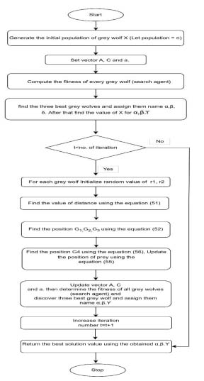
Figure 7.
Flow chart of the MGWOCS method
For each gray wolf.
1) Initialize random value of r1, r2.
2) Find the value of distance Gα, Gβ, Gδ using the equation (51)
3) Find the position G1, G2, G3 using the equation (52)
One more term G4 is find out using the equation (56)
Update the position of prey using the equation (55)
Update vector A, C, and a, then determine the fitness of all gray wolves (search agent) and discover three best gray wolf and assign them name α, β, δ. After that update the magnitude of Xα, Xβ, Xδ.
Increase iteration number t=t+1.
5. Repeat step 4 until criteria fulfills or maximum number of iterations achieved.
5. Implementation of the Proposed Techniques
An experimental model of a 2 MW DFIG-operated wind generation system is used in this work. A Simulink model of the DFIG-based wind generation system is developed in MATLAB to test and validate the proposed controller optimization by the MGWOCS method. A simulation model of DFIG [25, 26, 30] is given in Figure 8. The data for the test DFIG system are given in Table 1.
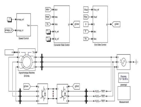
Figure 8.
Simulink model of DFIG
Table 1.
Datasheet of the 2 MW DFIG systems
| Specifications | Values |
|---|---|
| Rotor Equivalent Resistance Rr | 0.00289Ω |
| Stator Equivalent resistance Rs | 0.00259Ω |
| Inductance of Rotor Lr | 0.002586 H |
| Stator load Ls | 0.002587 H |
| Mutual-Inductance M | 0.0025 H |
| Real power proportional gain KP | 2.42 |
| Reactive power proportional gain KQ | 2.34 |
| Rated power P | 2MW |
| Frequency f | 50 Hz. |
| Generator (EM) Torque Tem | 13000 N-M |
The optimum tuning of the PI controller parameter is obtained by running the MGWOCS algorithm in Matlab. These tuned values of PI controller parameters are fed into the Simulink model of DFIG. In this model, a sudden change in load for t = 4 seconds is created to simulate the fault conditions. And the output waveform is plotted for true power, reactive power, emf, and current, as shown in the result section. The Jaya algorithm and the Whale optimization algorithm are also implemented on the same experimental model Simulink. Results obtained by MGWOCS and are compared with the Jaya algorithm and the Whale optimization algorithm.
6. Results and Analysis
In this section, the result waveforms acquired from the experimental model are plotted and compared for different methods. Values obtained through the Jaya optimization method [27, 28], the MGWOCS method, and Whale optimization [29] are fed into the model of DFIG, and the results are mapped.
Figure 9 shows the active power variation when the PI controller is tuned by the MGWO-CS method (blue color), the Jaya optimization method (yellow color), and the Whale optimization controller (green color), respectively. Figure 9 depicts that the output power of DFIG optimized by MGWO-CS and Jaya optimization is much better than the output with the Whale optimization controller.
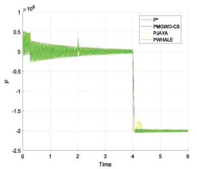
Figure 9.
Variation of the active power
Figure 10 shows the change in reactive power when the controller is implemented over time. The diagram in Figure 10 illustrates that the output power of DFIG optimized by MGWO-CS and Jaya optimization is much better than the output with the Whale optimization controller. When the machine is loaded, load torque is increased, which results in an increase in reactive power demand, which disturbs the voltage profile of the dc link as well. Figure 11 shows that MGWO-CS [30] gives better results and contains fewer transients than Whale optimization and the Jaya algorithm.
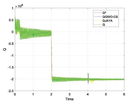
Figure 10.
Reactive power variation with respect to time for DFIG with different optimization method
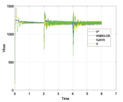
Figure 11.
DC link voltage variation with different optimization method
It is observed here that there is a large overshoot in the bus voltage. This large overshoot is due to an increase in the sensitivity of the system. It is well known that feedback control systems increase the sensitivity of the system, which increases the overshoot [30,31,32]. This may be considered the drawback of using the feedback control system with the PI controller, but in the DFIG system, stator winding is linked directly to the grid; hence, our main objective is to control the stator output, which is fulfilled in this work. The DC link is not directly linked to the load or grid, so it is not directly affecting the output power quality.
This transient is also not harmful for the grid or load because this DC link is not directly fed to the grid or load. To control this voltage, there is a capacitor or battery in between two converters that acts as an eliminator for these spikes, and this transient in voltage can also be controlled through a grid-side converter. The comparative results of the proposed methods with other techniques are given in Table 2.
Table 2.
Comparative results of different methods
| Parameters | Normal PI | PI optimized by WOA [28] | PI optimized by MGWO-CS | PI optimized by Jaya Optimization |
|---|---|---|---|---|
| Rise Time | 0.0885 | 0.0314 | 0.0263 | 0.0287 |
| Settling Time | 0.1363 | 0.0535 | 0.0386 | 0.0412 |
| Overshoot | 1.9099 | 1.12 | 1.08 | 1.10 |
| Undershoot | 0.85 | 0.809 | 0.913 | 0.956 |
| Peak | 1.6171 | 1.415 | 1.378 | 1.504 |
Responses obtained by different optimization techniques for the proposed practical wind generation model with the DFIG system are shown in Table 2.
Table 2 depicts that WOA, MGWO-CS, and JOA are all three methods improving the response and among the three best responses obtained from PI optimized by the MGWO-CS method.
The best value of a new factor γ, which is used in the suggested MGWOCS to modify the encircling and position update calculations, is also tested by comparing the convergence speed. It is observed that convergence speed varies with γ.
Convergence is compared for different values of γ. The values of γ are taken as 0.93, 1, 1.2, and 1.4. From Figure 12, it can be concluded that the function converges fast when the value of γ is 1.4. Figure 13 shows the THD measurement of output current from DFIG optimized by MGWO-CS Optimization.
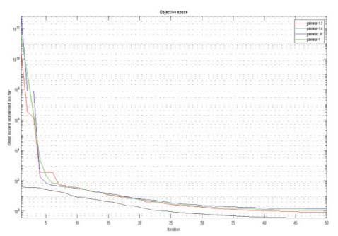
Figure 12.
Effect of γ on convergence plot
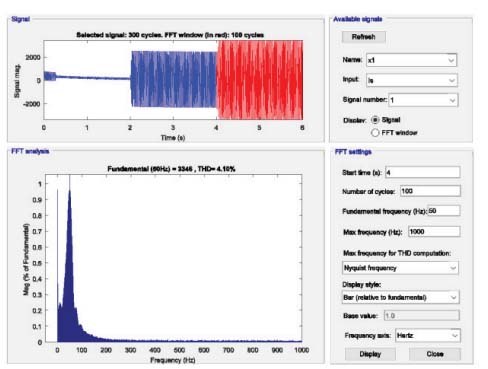
Figure 13.
THD measurement in DFIG optimized by MGWO-CS Optimization
Figure 13 shows the FFT analysis input load is tested at 5 sec, where the fundamental frequency is 50 Hz, and the achieved THD (total harmonic distortion) is 4.10%, which is less than 5% at the acceptable limit [32, 33].
6.1. Comparative Analysis in Terms of Convergence and THD Values
The convergence characteristics of GWO, MGWO-CS, and Jaya optimization methods are shown in Figures 14, 15, and 16, respectively.
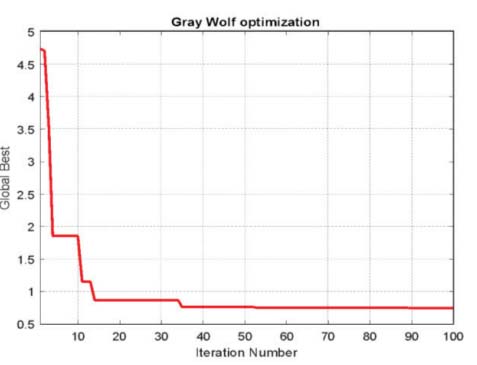
Figure 14.
Graph of Convergence for GWO method
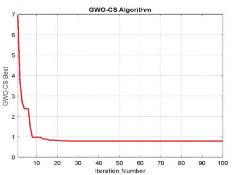
Figure 15.
Graph of Convergence for MGWO-CS method
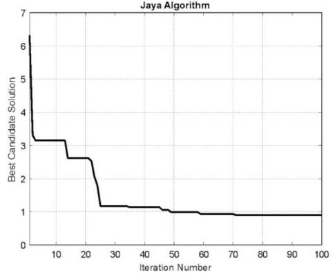
Figure 16.
Graph of Convergence for Jaya Optimization Method
Table 3.
Comparison of obtained THD values and convergence speed of different techniques
| S. No. | Technique used for optimization | THD Values | Number of iterations required to converge |
|---|---|---|---|
| 1 | Jaya Optimization Method | 4.49 | 71 |
| 2 | GWO Method | 5.52 | 52 |
| 3 | MGWO-CS Method | 4.10 | 12 |
THD values of stator current obtained through different controllers are also compared. Table 3 shows that THD values and convergence rate are found to be better for the MGWOCS method than the GWO and Jaya optimization methods.
7. Conclusion
DFIG-WECS is mathematically modeled, and its rotor-side PI controller is successfully designed. The Novel Modified Hybrid Gray Wolf Cuckoo Search Algorithm is applied in this work to obtain the optimum value of the parameters of the controller. The value of gains obtained from the optimization method is fed to the 2 MWDFIG Simulink model. Simulation results are compared with those obtained using the Jaya algorithm and the Whale Optimization algorithm. A sudden transient is created at t = 4 seconds, and the waveform of voltage, current, and power is analyzed. From analyzing the waveforms, it is concluded that MGWOCS gives satisfactory results. Performance is also evaluated in terms of rise time, settling time, overshoot time, and undershoot time, and it was found that MGWOCS is giving much better results than other methods. The convergence rate is also compared for different values of γ. It is found that the convergence rate depends on γ, and the convergence rate is highest when the value of γ is 1.4. The results of MGWOCS and GWO are illustrated. THD and convergence speed are compared, and it is concluded that convergence speed is increased. Also, THD values are found to be lowest when using a controller optimized through MGWOCS. The work’s future objective is to analyze the efficacy of the MGWOCS method on other DFIG test systems. Also, this method can be compared with more new Metaheuristic optimization methods.