

Table 1.
Survey related to the traditional MPPT approaches
| References | Methodology | Advantages | Limitations |
|---|---|---|---|
| Shaik rafi kiran et al (2022) [21] | artificial neural network (ANN) based MPPT | It achieves better tracking efficiency with minimized oscillation of MPP. | However, this system applicable for partially shaded PV system. |
| Faizan Mehmood et al (2020) [22] | Fuzzy-based MPPT | At the period of transient condition, this technique attains better performance with efficient power delivery. | Nevertheless, it has steady state oscillations and system complexity. |
| Sara et al (2021) [23] | ANFIL-based MPPT | It has higher accuracy, faster response with better tracking. | However, due to increasing number of rules, the system complexity is enhanced. |
| Chaoping rao et al (2022) [24] | Perturb observe (P&O)-Based MPPT | It attains minimized steady-state error with better tracking efficiency. | Nonetheless, the fluctuation around MPP and complexity leads to degradation of system performance. |
| Pawan Kumar Pathak et al (2021) [25] | modified incremental conductance (INC)-based MPPT | MINC attains high tracking efficacy with effectual convergence speed. | However, execution time needs to be considered in further studies. |
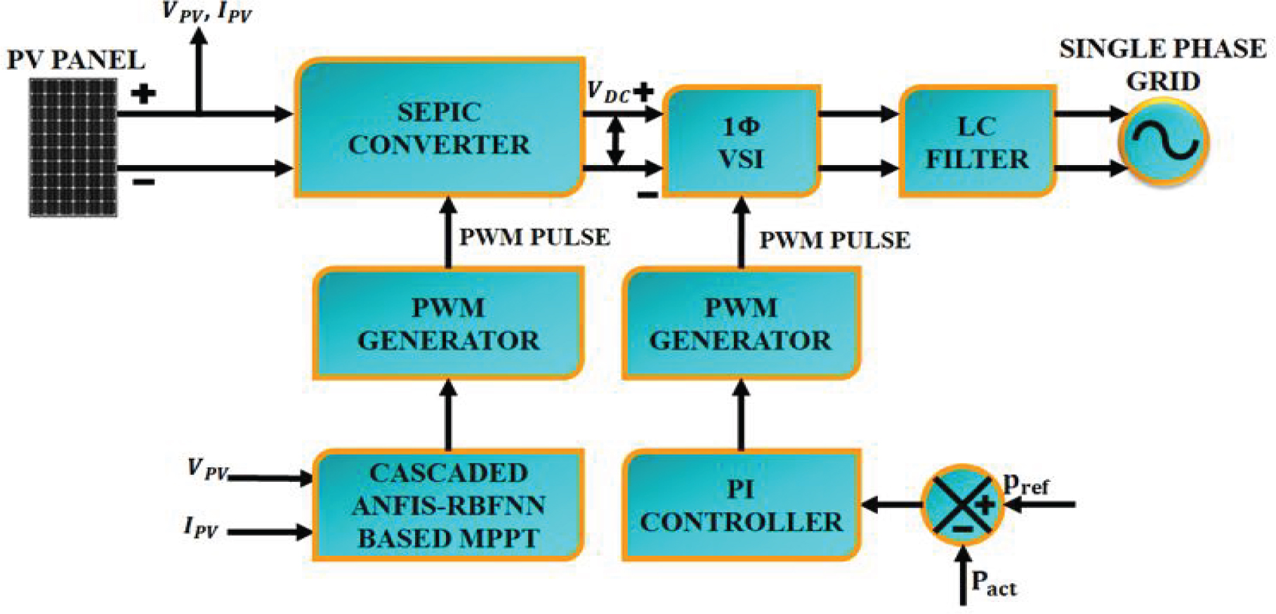
Figure 1.
Block diagram of the proposed work
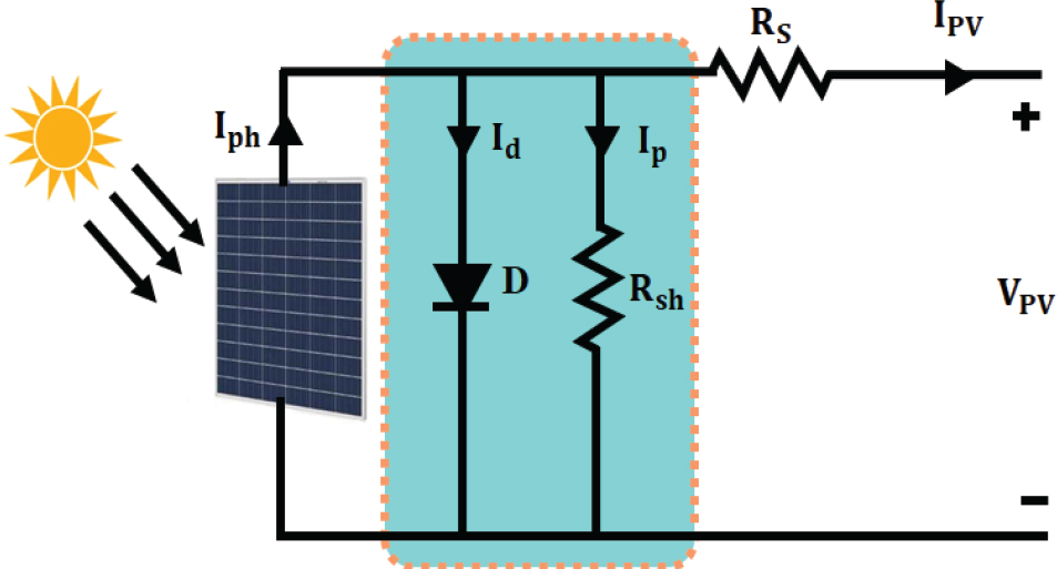
Figure 2.
Circuit diagram of a PV module
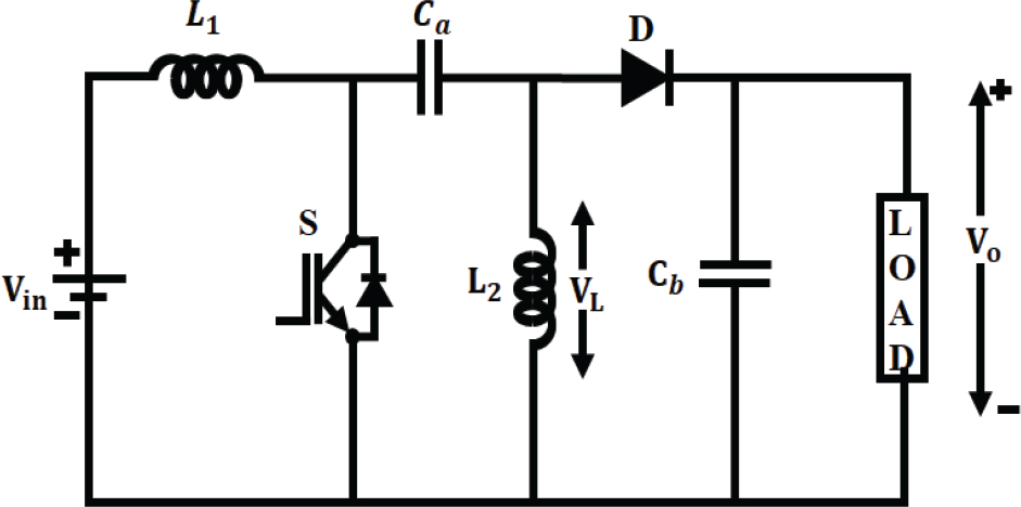
Figure 3.
SEPIC converter circuit diagram
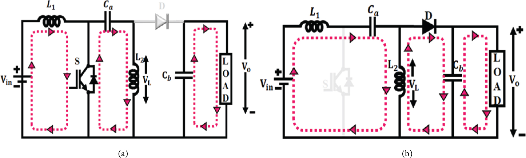
Figure 4.
Modes of operation
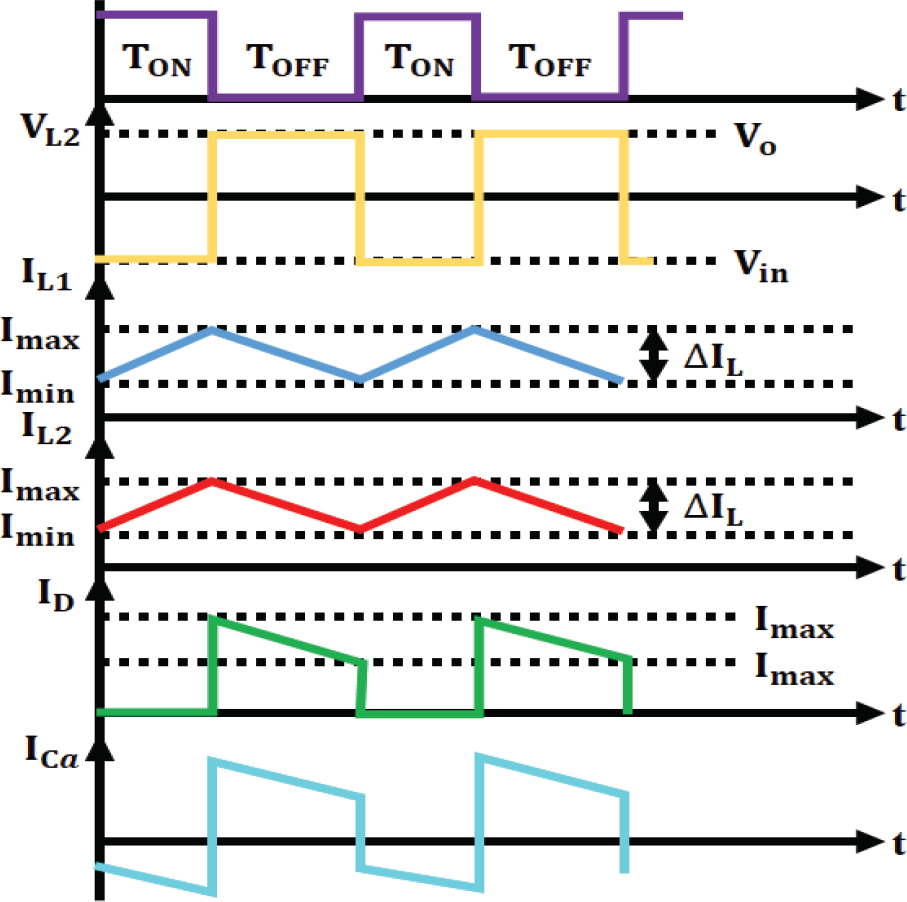
Figure 5.
Switching waveform for the proposed converter
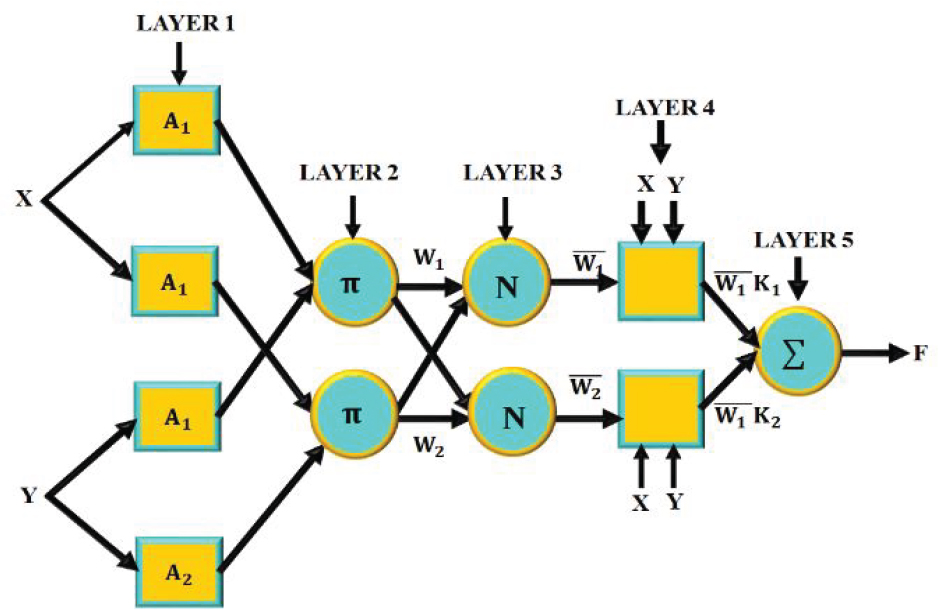
Figure 6.
Structure of ANFIS
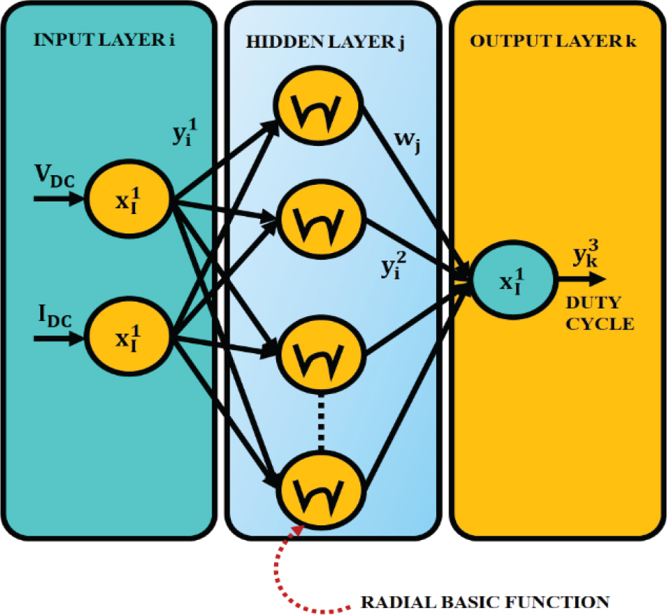
Figure 7.
RBFNN architecture
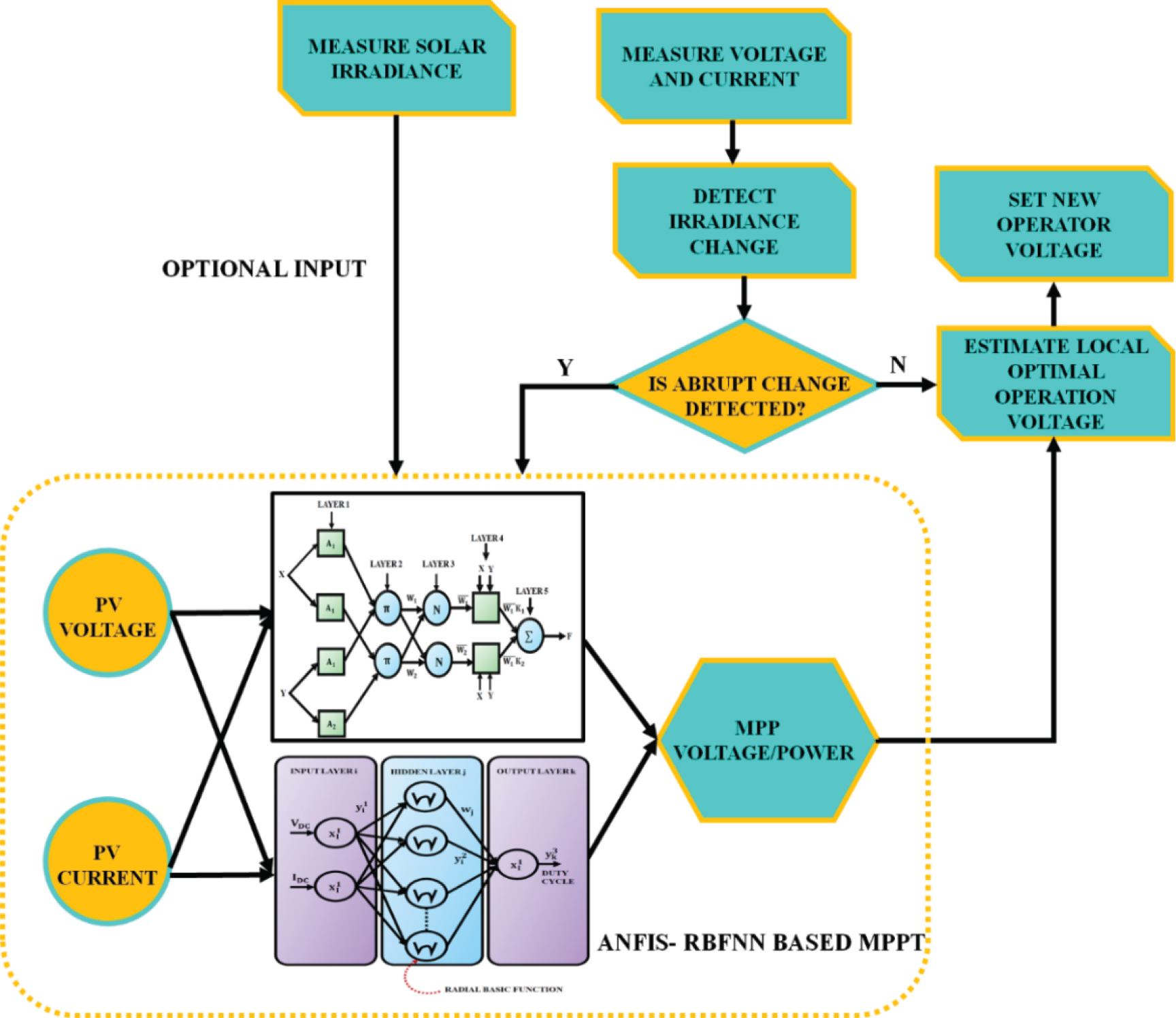
Figure 8.
Proposed cascaded ANFIS–RBFNN-based MPPT
Table 2.
Parameter Specifications of Proposed System
| Parameter | Description |
|---|---|
| PV system | |
| Open circuit voltage | 37.25V |
| Short-circuit current | 8.95A |
| Series-connected solar panel | 2 |
| Parallel-connected solar PV cell | 25 |
| Maximum power voltage | 29.95V |
| Maximum current | 8.35A |
| SEPIC | |
| Switching frequency | 10kHz |
| Ca, Cb | 4.7μF |
| L1, L2 | 1 mH |
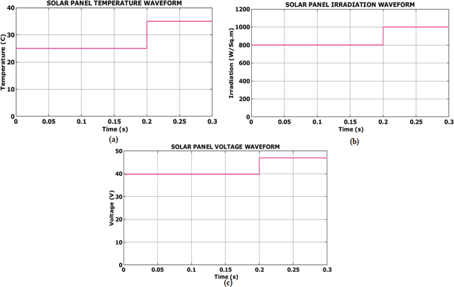
Figure 9.
Solar module waveform for case 1. (a) Temperature; (b) irradiation; (c) voltage
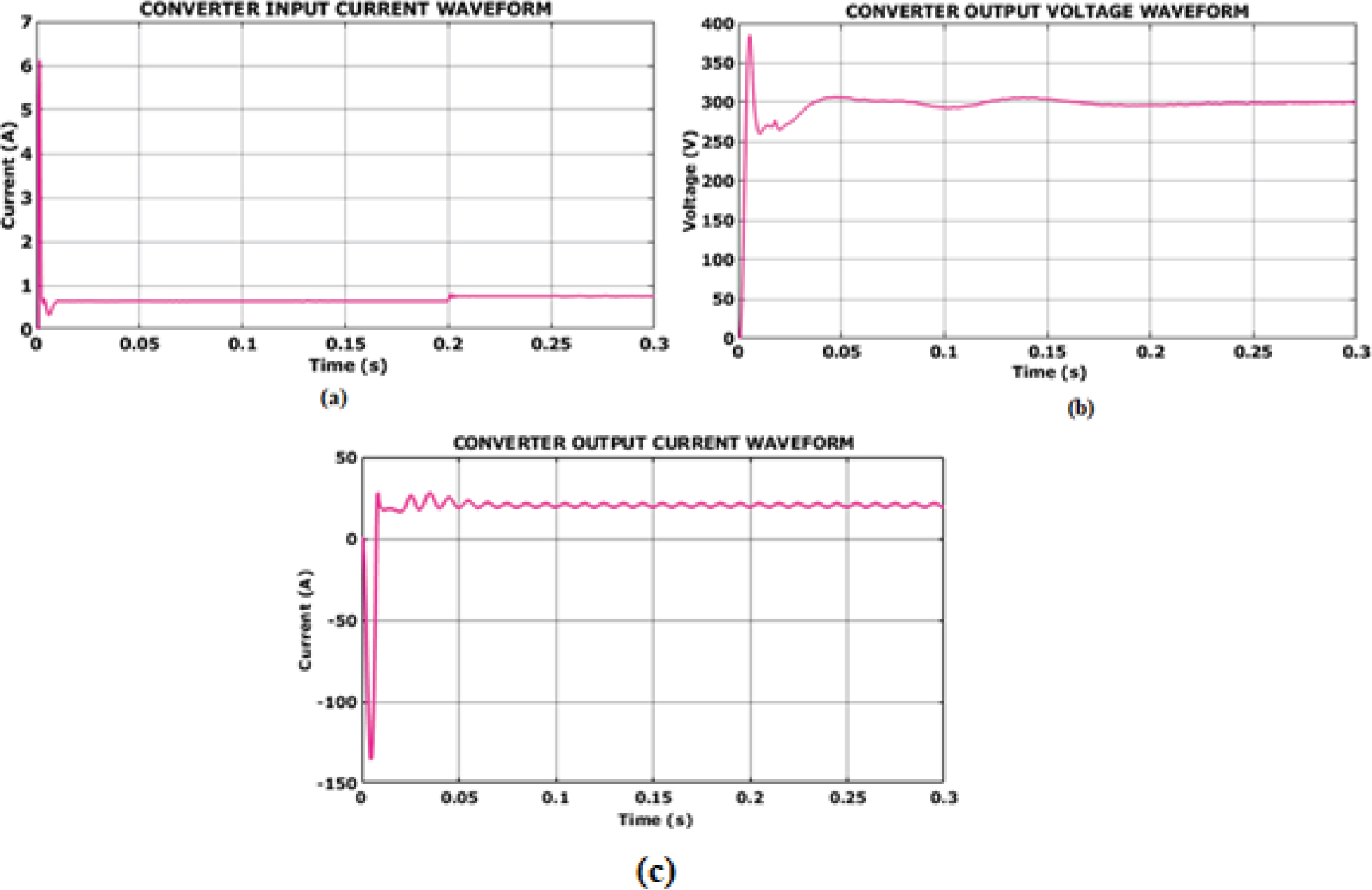
Figure 10.
Converter output waveform for case 1
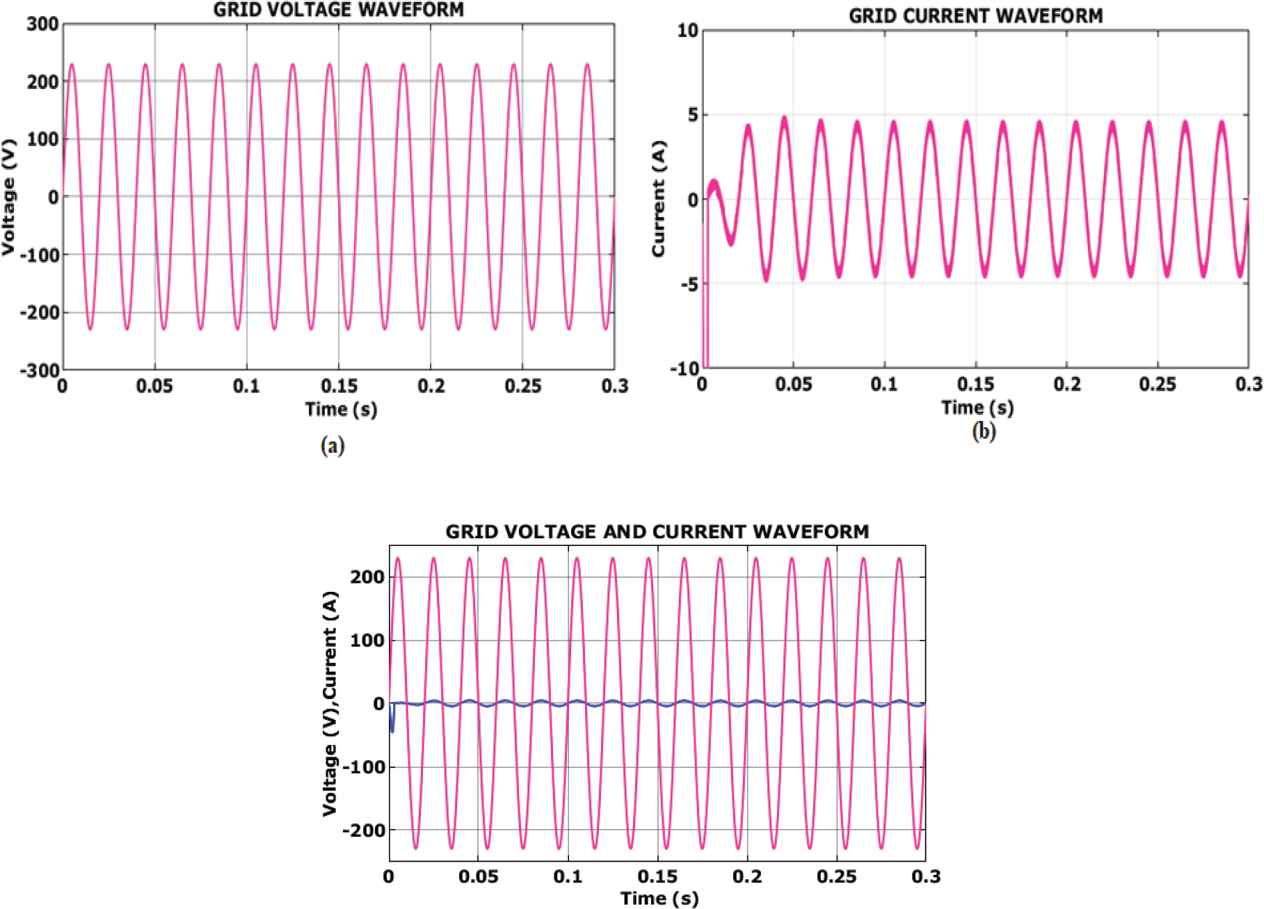
Figure 11.
Grid waveform. (a) Voltage; (b) current; (c) in-phase voltage and current waveform
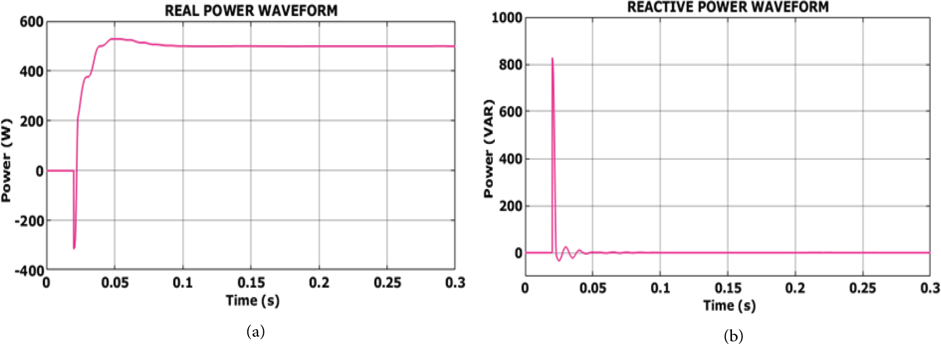
Figure 12.
Real and reactive power waveform
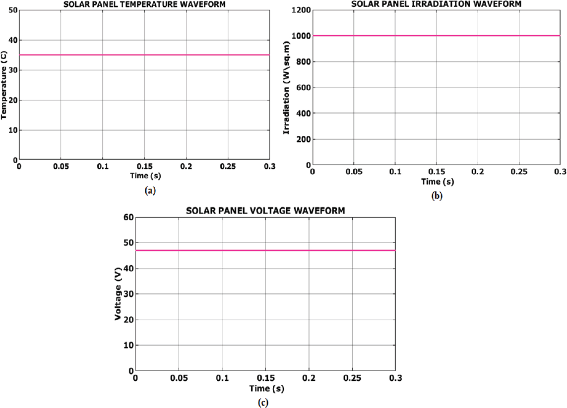
Figure 13.
Solar panel waveform for case 2
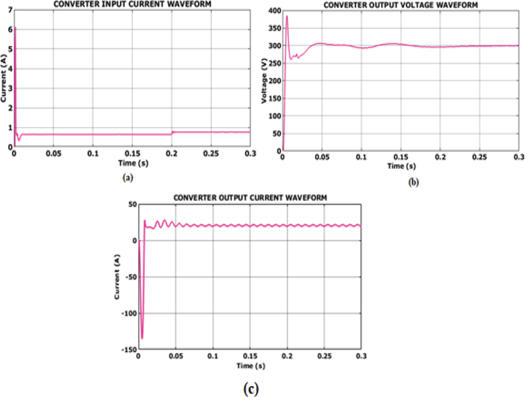
Figure 14.
Converter waveform for case 2
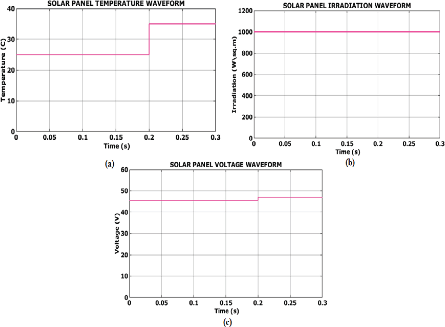
Figure 15.
Solar panel waveform for case 3
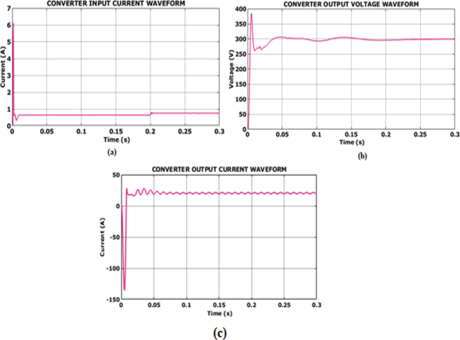
Figure 16.
Converter waveform for case 3
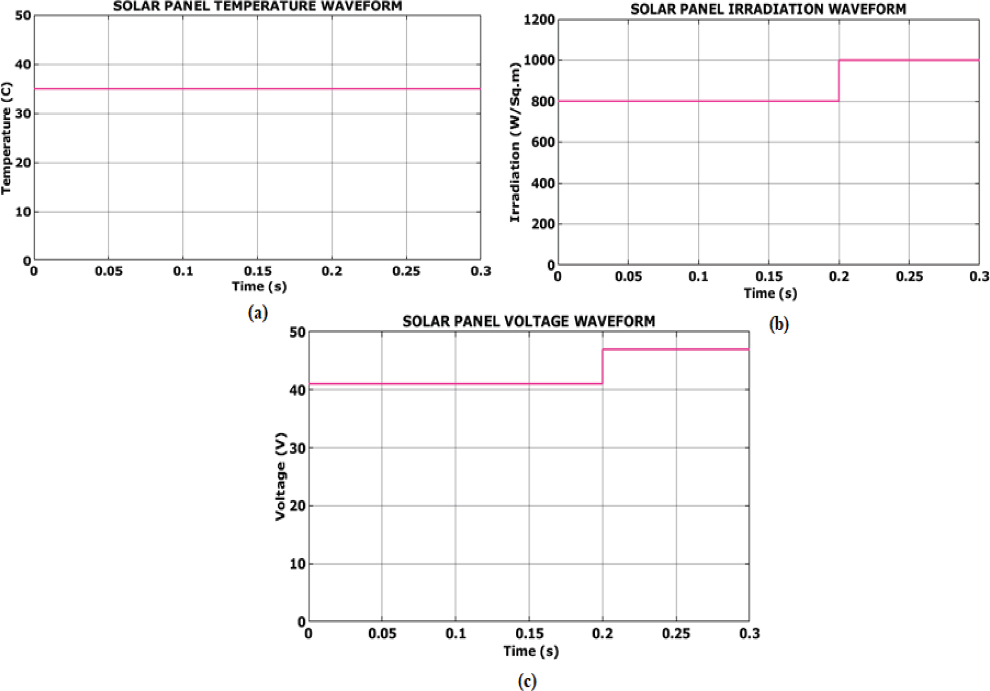
Figure 17.
Solar panel waveform for case 4
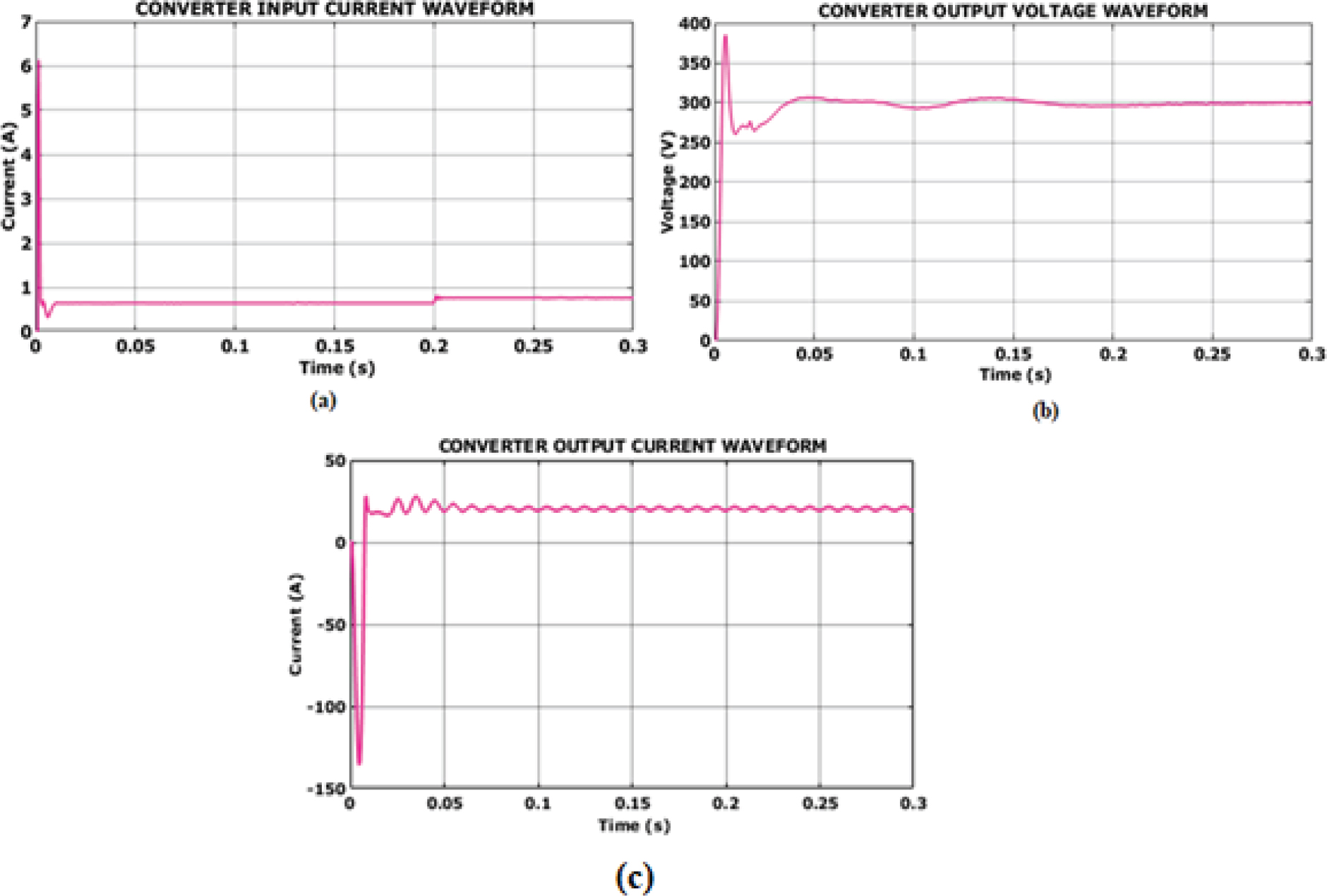
Figure 18.
Converter waveform for case 4
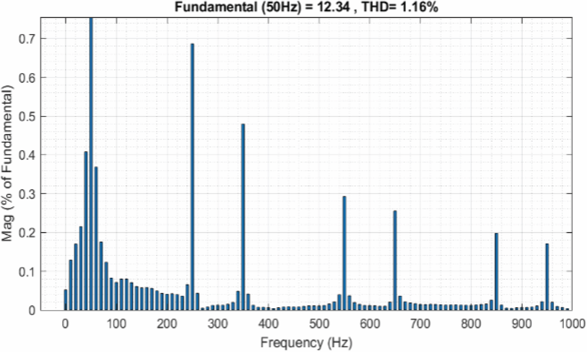
Figure 19.
THD waveform for the proposed work
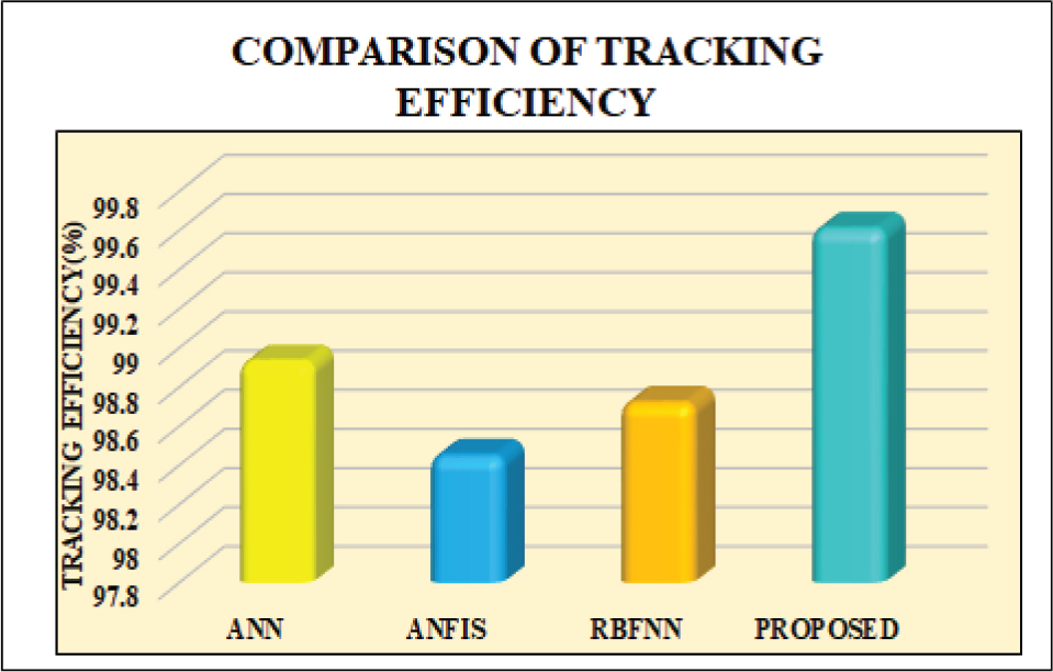
Figure 20.
Comparison of tracking efficiency
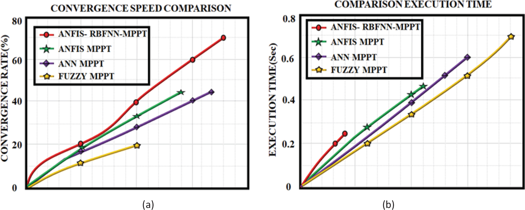
Figure 21.
Comparison of (a) convergence speed and (b) execution time