

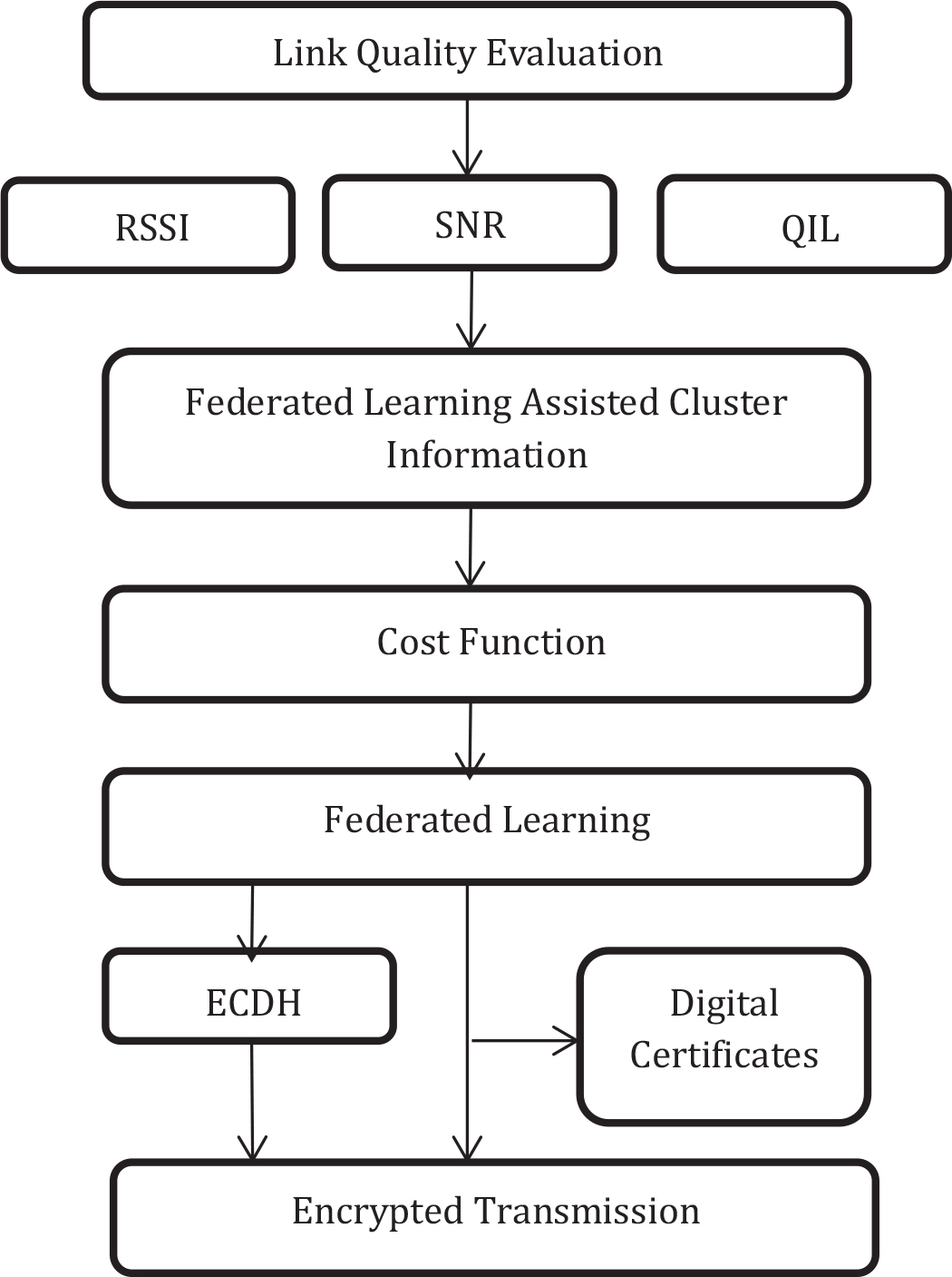
Figure 1.
Block diagram of FL-ERCF protocol showing three core phases: Link Quality Evaluation, Federated Learning-Assisted Cluster Formation, and Encrypted Transmission
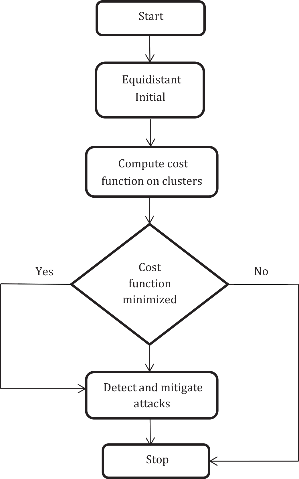
Figure 2.
Flow of secure cluster formation and attack detection using cost function and trust scores in FLERCF
Table 1.
Simulation Environment
| Parameter | Value / Range |
|---|---|
| IoT Nodes | 50,100,200,300, 400,500 |
| Simulation Area | 500 m × 500 m |
| Initial Energy per Node | 0.6 Joules |
| Simulation Time | 200 seconds |
| Communication Range | 50 m |
| Node Deployment | Random Uniform |
| Mobility | Static |
| Routing Protocols Evaluated | FL-ERCF, EESR, HSR |
| Attackers (Malicious Nodes) | 10% and20% oftotal nodes |
| FL Round Interval | Every 10 simulation seconds |
| FL Model | Decision Tree Classifier (Scikit-learn) |
| FL Optimizer | FedAvg (FederatedAveraging) |
| Security Technique | ECDH with Digital Certificates (DCESC) |
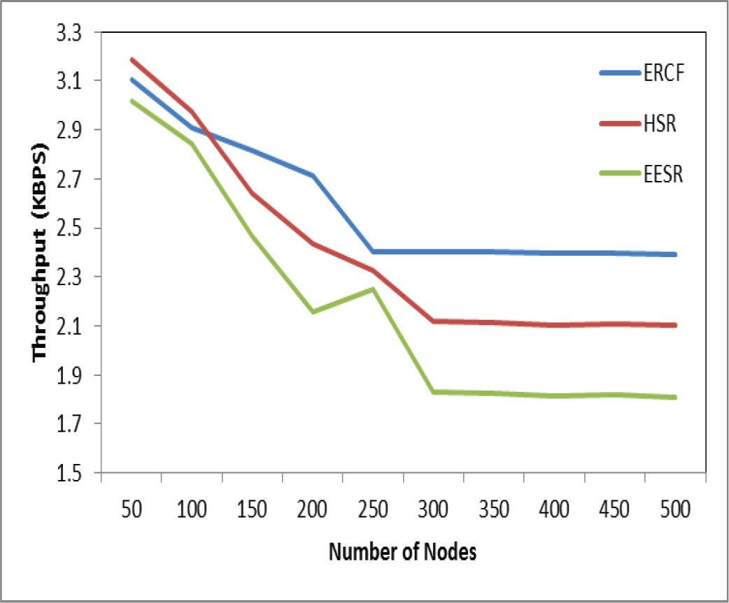
Figure 3.
Throughput of IoT network with different count of IoT nodes
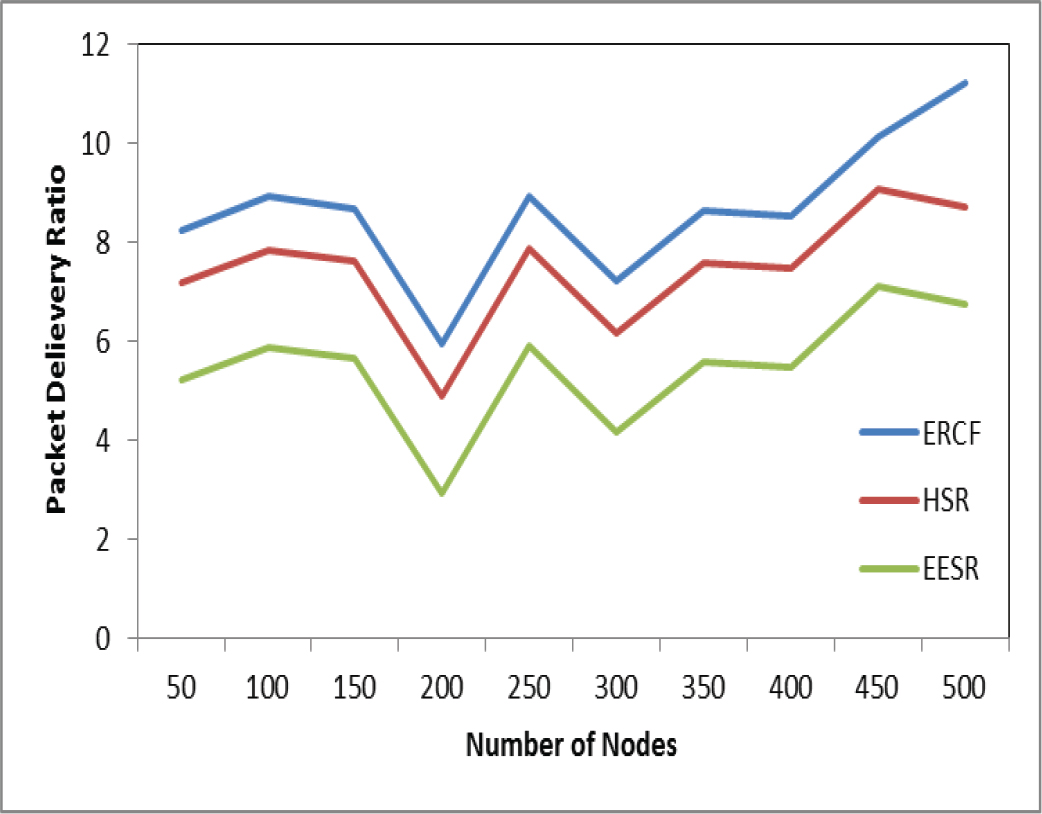
Figure 4.
Packet Delivery Ratio (PDR) (%) of IoT network with different count of IoT nodes
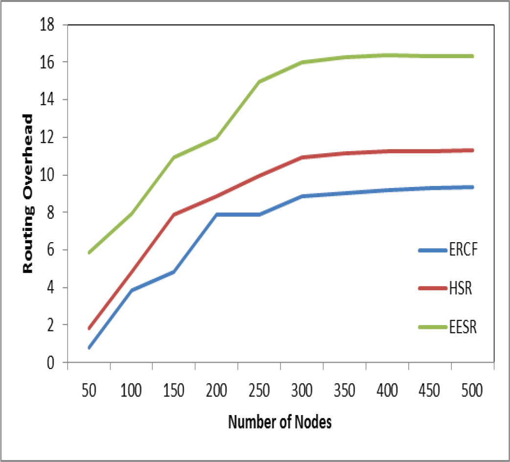
Figure 5.
Routing Overhead of IoT network with different count of IoT nodes
Table 2.
Average Throughput (%) under different node densities
| Nodes | FLERCF | HSR | EESR | pvalue (FLERCF vs HSR) | p-value (FL-ERCF vs EESR) |
|---|---|---|---|---|---|
| 50 | 96.2 | 84.1 | 79.3 | <0.01 | <0.01 |
| 250 | 91.8 | 82.5 | 76.4 | <0.01 | <0.01 |
| 500 | 87.5 | 83.0 | 78.2 | <0.05 | <0.01 |
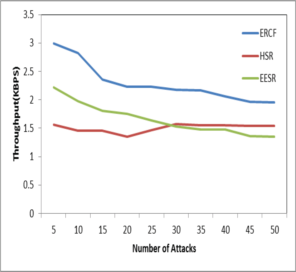
Figure 6.
Throughput of IoT network with different count of attacks
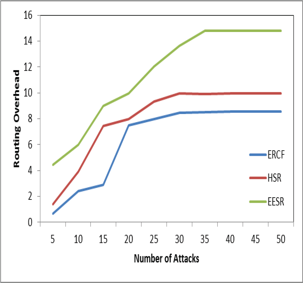
Figure 7.
Routing overhead of IoT network with different count of attacks
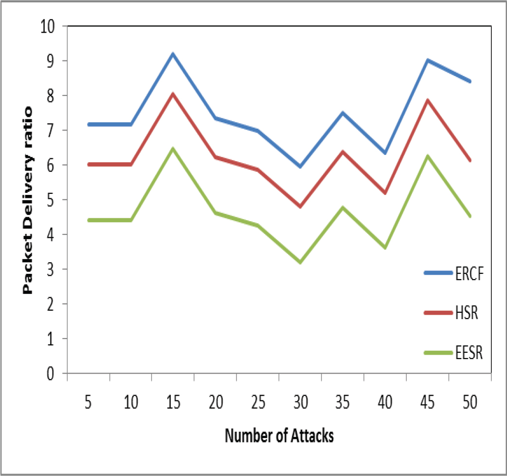
Figure 8.
Packet Delivery Ratio (PDR) (%) of IoT network with different count of attacks