
Introduction
A Forensic Document Examiner (FDE) is an expert on print system defects from both traditional commercial printing processes and modern office/home printing processes. FDE training programs involve extensive study of printing processes, which include determining the class of printing based on visual/microscopic examination of distinct class features. FDE training programs also include the forensic comparison of reference standards to printed documents, whereby distinguishing and class printing characteristics are compared and evaluated possibly leading to a determination of association or non-association (1). After training is completed, it is essential for a FDE to maintain their expertise and stay abreast of changes in printing technologies which may have an impact on forensic examinations and comparisons. While it may be impractical for FDEs to constantly keep a finger on the pulse of the printing industry, it is certainly prudent to refresh their knowledge of these technologies before conducting a printing examination.
Print defects in photocopier systems are often colloquially referred to by FDEs as ‘trash marks.’ In the Scientific Working Group for Forensic Document Examiners (SWGDOC) Standard Guide for Examination of Documents Produced with Toner Technology (2) (formerly ASTM Standard E2390), FDEs are advised to examine documents for distinguishing characteristics such as security features, wear and damage defects, misalignments, reproducible marks, voids, and improper or extraneous toner transfer. For the purposes of this paper, these distinguishing characteristics will be referred to as print defects or defects. Print defects originate from various components of the device, such as the drum, platen, slit glass, or cover. Examination and comparison of these defects can possibly lead to either 1) common source determination or identification or 2) different source determination or exclusion. It is necessary for the FDE to understand the components of a suspect machine, and how the particular photocopier system works, in order to properly interpret the possible origin(s) of print defects. Office machines utilizing toner technology typically include photocopiers, laser printers, facsimiles, and multi-function machines. For the purposes of this paper, the focus will be primarily on photocopiers, which will be referred to as photocopier systems or copiers, and the process of printing as the copying process.
Advances in photocopier technology from analog systems to digital systems changed the configuration of many copiers using an automatic document feeder (ADF) to include a separate scanner glass, in addition to the traditional glass platen (Figure 1) (3). This separate scanner glass is called by different terms, such as slit glass, depending on manufacturer and model; however, its function and impact on forensic document examinations remain the same. This configuration change has an impact on the possible origin of photocopier defects and their role in comparisons. This paper discusses how this component is utilized in the copying process and why print defects manifest themselves differently.
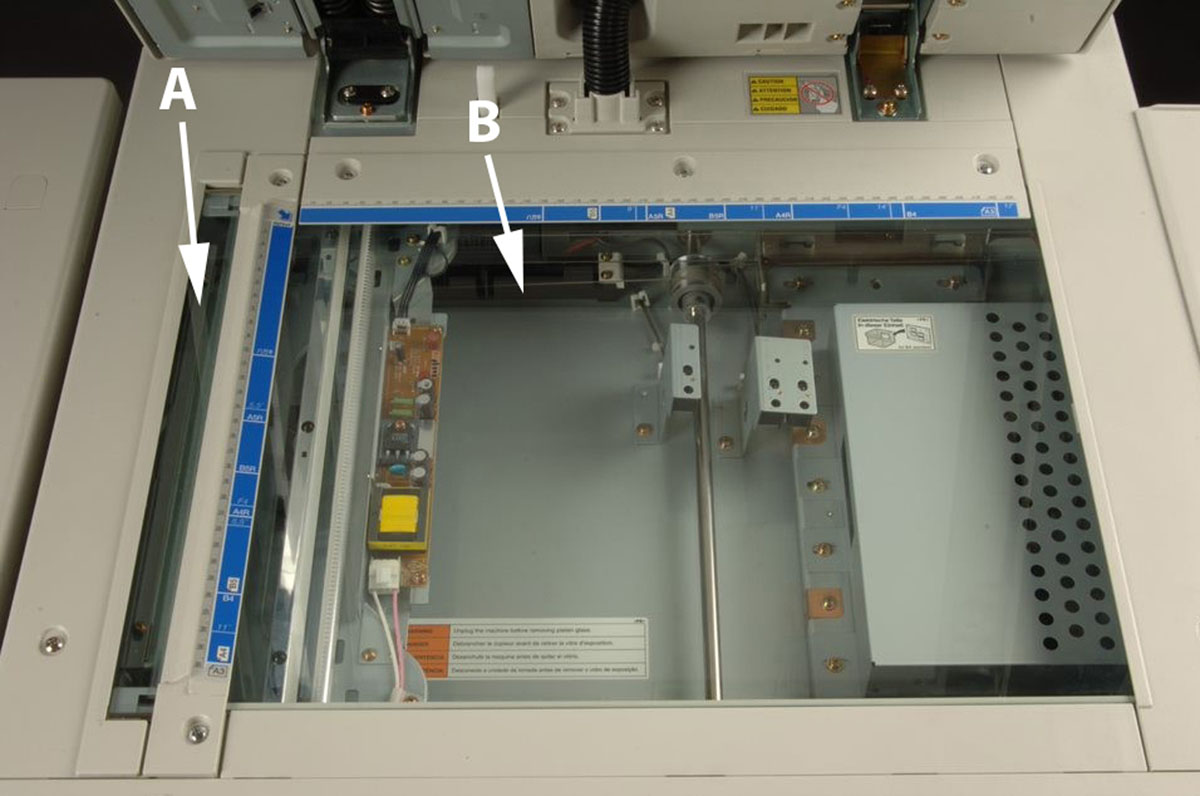
Figure 1
A) slit glass, B) platen.
The SWGDOC Standard for Examination of Documents Produced with Toner Technology states in section 3.2.36 that the term ‘slit glass’ is defined as ‘alternate scanning surface found in some digital photocopiers used in conjunction with an automatic document feeder (2).’ The term for this component has been known by several names in the industry including slit glass, scanner glass, partition glass, and narrow glass. Recent consultation with an industry expert indicated a commonly used industry term for the slit glass is constant velocity transport (CVT) glass (4). For purposes of this paper, slit glass will be used.
The slit glass is the scanning surface used in conjunction with the ADF. When the ADF is utilized on a digital copier equipped with a slit glass, the glass platen is not part of the imaging process. In contrast to the traditional configuration of a stationary document and a moving imaging device, this system uses a fixed imaging device while the document moves over the slit glass.
Methods and Materials
An experiment was designed to study the effect of a defect on the slit glass on a copied document. The materials used included:
One clear acetate overlay printed with simulated defects comprised of various shapes (triangles, quote bubbles, musical notes, and diagonal lines) with varying densities, ‘shapes overlay’ (Figure 2)
Three clear overlays printed with simulated defects, comprised of blocks with varying densities and size, ‘blocks overlay’ (Figure 3)
Konica 7155 digital black and white copier (Figure 4)
Original document printed from a toner technology printer comprised of a full page of text, having no visible printing defects (Figure 5)
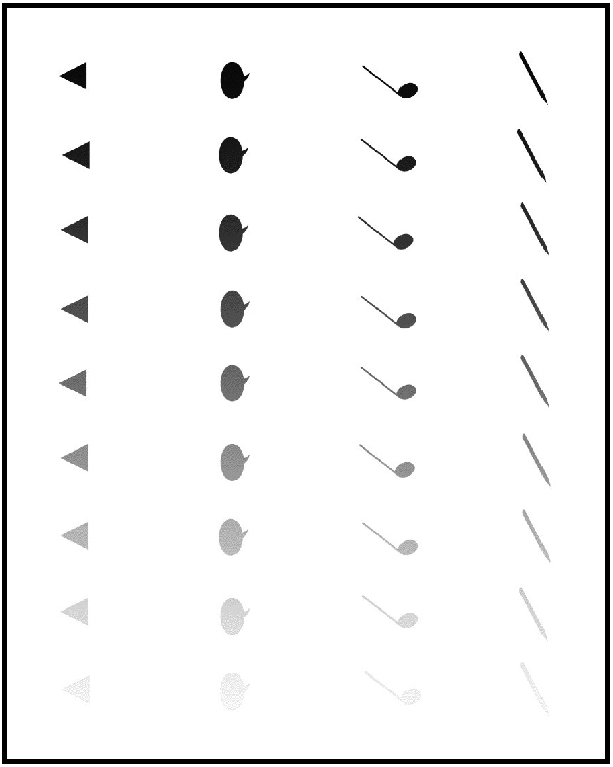
Figure 2
Shapes overlay with simulated defects – various shapes and densities.
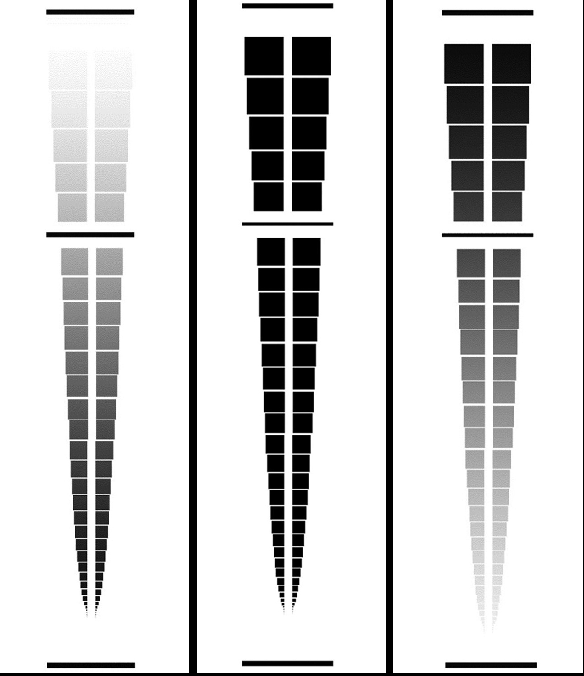
Figure 3
Block overlays with simulated defects - blocks with varying densities and size (increasing density, solid density, diminishing density.).
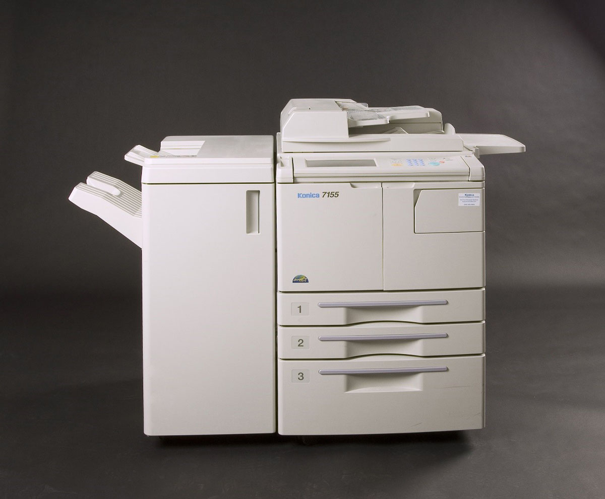
Figure 4
Konica 7155 digital black and white copier.
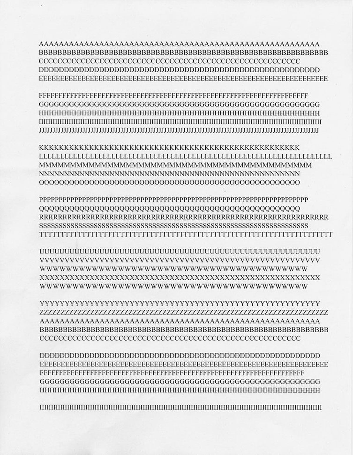
Figure 5
Original document having no visible printing defects.
To conduct the experiment, the overlay(s) was affixed over the platen glass and the original document was placed on top of the overlay(s), both in portrait orientation, and exemplar copies were collected. This and all subsequent exemplars were collected using three density settings on the copier: darkest, lightest, and middle (two exemplars per setting). The three blocks overlay(s) were placed consecutively (side by side) across the platen with the original document on top and six exemplar copies were collected. Subsequently, the shapes overlay with the original document on top was placed on the platen and six exemplar copies were collected.
Next, each blocks overlay was separately affixed over the slit glass, in portrait orientation, and the original was placed into the ADF, in portrait orientation, and six exemplar copies of each blocks overlay were collected at varying densities for a total of eighteen exemplars. The shapes overlay was affixed over the slit glass, in portrait orientation, first lining up the triangle column and then moving left to right to each additional shape column for each set of exemplars. The original was placed into the ADF, in portrait orientation, and six exemplar copies of each shape column were collected at varying densities for a total of twenty-four exemplars.
This method produced two sets of exemplars, one set capturing images (defects) from the platen glass (12 exemplars) and the other capturing images (defects) from the slit glass (42 exemplars).
After the exemplars were collected, visual examination and comparison was conducted of the simulated defects, original document, and exemplars. Observations of printing defects on the exemplars were made including, but not limited to, placement, shape, size, and density.
Discussion
After the examinations were conducted, it was concluded exemplar copies originating from the platen reproduced the defects as they appeared on the platen overlay (Figure 6), whereas copies processed through the ADF (imaged on the slit glass) generally resulted in a parallel series of lines of varying width with the smallest defects not reproducing at all (Figure 7).
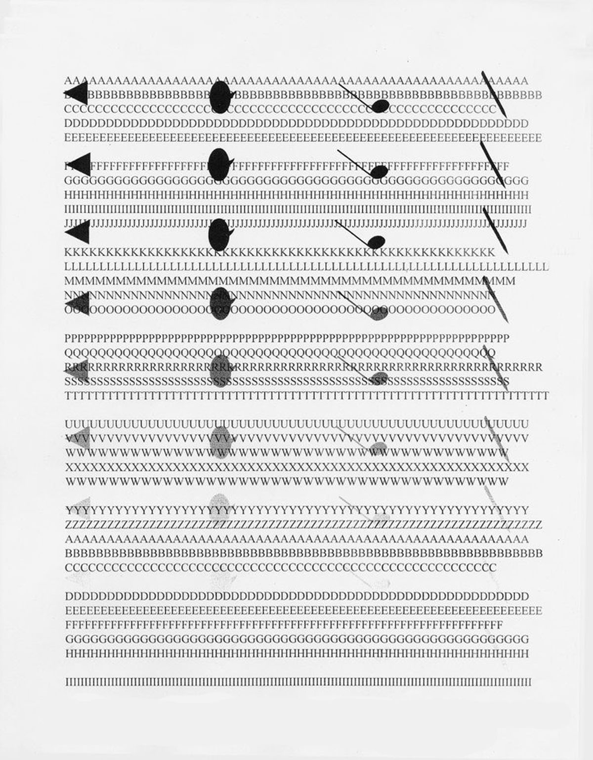
Figure 6
Photocopier defects from platen glass using the shapes acetate overlay (Figure 2) with the copier’s lightest density.
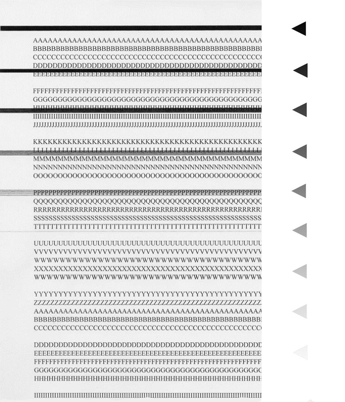
Figure 7
Photocopier defects from slit glass using the triangle shape overlay (Figure 2) with the copier’s lightest density.
In this test, two factors regarding density were considered: the density setting on the copier and the density of the trash mark. The exemplar copies were made using three density settings on the copier: darkest, lightest, and middle. The simulated trash marks on the shapes overlay and two of the blocks overlays have graduated densities ranging from fully opaque to transparent. On both the exemplar copies from the platen and the slit glass, a solidly opaque trash mark when copied at different density setting does not visually change at all or the change is barely perceptible.
When the trash mark has less opacity or has some transparency, a change in the density setting of the copier also visually changes the trash mark, making it denser/less transparent at higher density setting and less dense/more transparent at the lower density setting or even not reproducing at all. It was noted that when a very transparent trash mark was copied on the lightest density setting the trash mark was not reproduced at all, but the copy text was still present (Figure 8). However, when there is a solidly opaque trash mark on the slit glass and copies are made on the lightest density setting, the result is a solid black line defect until the defect is very small then it does not reproduce at all but rather the copied text lightened in that portion (Figure 9).
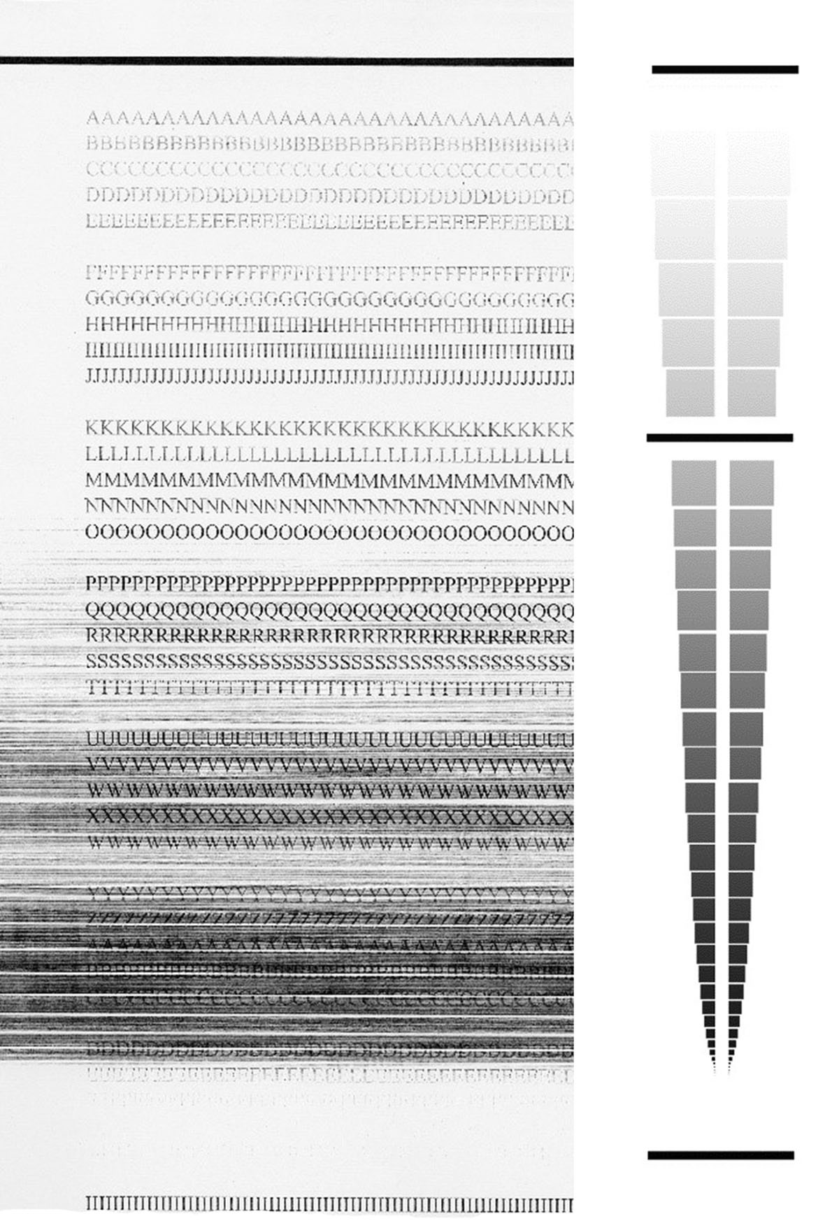
Figure 8
Exemplar collected from slit glass with the increasing density blocks using the lightest density copier setting.
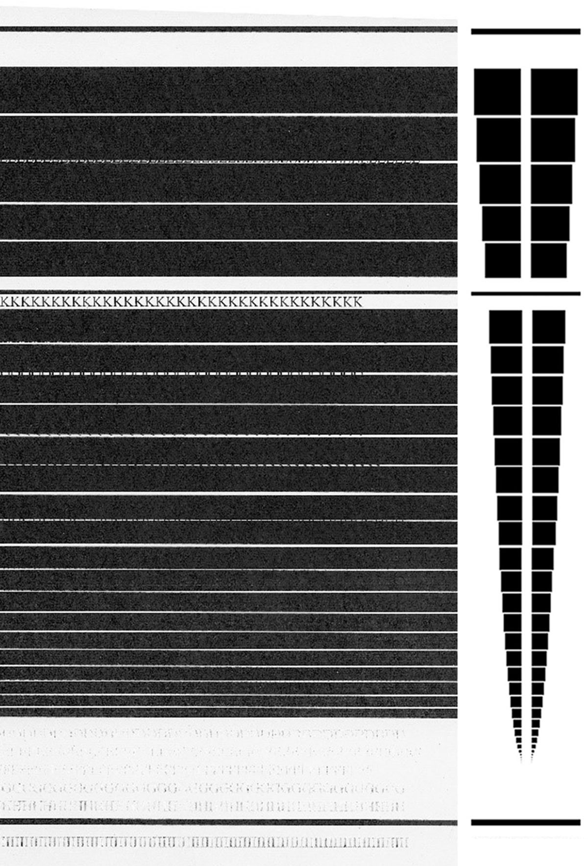
Figure 9
Exemplar collected from slit glass with equal density blocks using the lightest density copier setting. The defects remained dark, but the copied text lightened.
Understanding the difference between the moving imaging area and the fixed imaging area is key to understanding its effect on printing defects. A moving imaging system is found in both analog and digital copy systems, where the original document is placed on the platen glass only and the imaging component moves back and forth capturing the document. When a copier is equipped with an ADF, but does not have a slit glass, the interior of the top cover has a conveyor belt which moves the document to be imaged onto the platen glass and back into the ADF.
In a fixed-point imaging system, the original document moves over an imaging system which is fixed in place, as the name implies. This system is used in digital copiers equipped with both a slit glass and an ADF. The original document moves rapidly through a series of rollers through the ADF in front of the slit glass and empties back into the ADF document return area (5).
Many photocopier systems use both a fixed imaging and moving imaging system. Xerox introduced fixed imaging systems into the market in 1997 and competitors introduced these systems into the market in the early 21st Century. This type of imaging system was developed for speed and image integrity. It produces more accurate registration, less paper jams, and higher copying speeds. However, it created more problems including increased release of dust from the moving paper, and problems with undried correction fluid on paper transferring onto slit glass and users leaving fingerprints on slit glass (4).
The photocopy process employs the following stages: charging, imaging, exposing, developing, transferring, fusing, and cleaning. It is also referred to as indirect electrostatic process, electrophotography, and xerography; collectively referred to as ‘toner technology’ (6). Toner technology may employ both fixed-point and/or moving imaging systems. Despite the type of imaging system utilized, the document examination of the final product (toner on paper) remains the same. It should be noted that specialty coated papers can be used, however, are not required.
As stated above, photocopier association requires distinguishing characteristics comprised of extraneous markings produced because of defects which can be caused by imperfections, blemishes, marks, scratches, pits, opaquing fluid, tape/adhesive, smudges, fingerprints, dirt, and dust. The source location of distinguishing characteristics in a photocopy system can originate from the platen, cover, drum, and possibly other components.
Photocopier defects on the platen from a moving imaging system reproduce the defect’s morphology in approximately the same size and shape. However, photocopier defects on the slit glass from a fixed-point imaging system, do not reproduce the defect’s morphology on the copy. Rather, it results in a solid line, a series of thin lines, lightening of a printed area, or even a void. This will vary based on the size and density of the defect, and the density setting of the copier.
The SWGDOC Toner Technology standard directs FDEs in section 7.9.3, to ‘Note visible external components of the device such as the platen, slit glass, collators and cover/automatic document feeder that may contain physical evidence, obstructions, debris, correction fluid, marks, or scratches (2).’
As the standard directs, when taking exemplars from a copying device, one must consider all components of the machine. In the case of a copy device with an ADF, it is prudent to obtain exemplars from the platen glass, with and without a clean sheet of white paper over the platen, as well as collecting exemplars by running a clean sheet of white paper through the ADF.
In ‘Forensic Document Examination In The 21st Century,’ Tobin Tanaka gives guidance on proper collection of exemplars by explaining modern devices have at least two imaging areas: the copy platen for hand placement of documents and a slit glass used by the ADF (7). It is further explained that some devices have another scanning platen located in the mechanism of the ADF feeder to allow for simultaneous two-sided scanning. Therefore, the recommendation is to take exemplars from each copying surface at the darkest, lightest and medium contrast settings which includes exemplars from the ADF in single-sided and double-sided mode.
Another modern photocopier feature which should be considered is the simultaneous duplex handler. This research was originally conducted before the introduction of this feature; however, it is an important consideration in printing comparisons. According to the Xerox Corporation, a simultaneous duplex handler was introduced into the marketplace around 2013 by Xerox on the Xerox Color 550/560/570 models (4). This feature is integrated into the ADF and allows a document’s front and back to be scanned simultaneously, allowing for faster two-sided copying and less paper jams. Traditionally, two-sided printing required the user to turn the document over on the platen or ADF, or for the ADF to physically flip the original around. As users have likely experienced, this often led to paper jams in the ADF. This problem was addressed by the industry through simultaneous scanning, which introduces an additional slit glass with a fixed imaging system to scan the back side of the document. Simultaneous duplex handlers are currently in the marketplace in both color and monochromatic copiers. As a result, defects from one slit glass may be imparted onto the front of the copy, and defects from the other slit glass may be imparted onto the back of the copy.
Results
The documents copied utilizing the ADF on a copier equipped with a slit glass do not come into contact with the platen. Therefore, defects which may exist on the platen will not appear on the copy originating from the ADF and slit glass.
The same is true for the opposite, documents copied on the platen will not come in contact with the slit glass during imaging. Therefore, defects which may exist on the slit glass will not appear on the copy when the platen is used.
The size, shape, and density of any defects on the slit glass and on the platen will appear very differently on their respective copies.
Generally, if there are straight horizontal streaks on the page, an FDE should consider the defect may be from the slit glass.
Generally, if a defect on a copy is a ‘geometric-type’ shape, an FDE should consider the defect may be from the platen, inside of the cover, or drum.
A mere observation alone of a streak or geometric shape is not conclusive in this regard and a thorough comparison with complete and proper exemplars is required.
The size and density of a defect on the slit glass can influence the density and size of the lines on the copy.
Sizable defects on the slit glass will generally reproduce as lines on the copy.
Small defects on the slit glass may not be imparted on the copy at all.
The copy density setting on the copier can influence the density and size of the lines on the copy with the slit glass defects.
The copy density on the lightest setting when there are small dense defects present can cause a void area on the copy instead of a line with the slit glass.
Conclusion
It is crucial for FDEs to appropriately research and keep up to date with technology changes with office equipment in order to enhance and refresh their knowledge of office machines before undertaking a printing examination.
Do not assume if defects from the platen are not imparted on the copy, the document originated from another machine. Consider the defect(s) may have originated from the slit glass. When taking photocopier exemplars, be sure to take exemplars from the ADF using both one-sided and two-sided settings and note which side is which on the exemplars. It is advisable to photograph the machine and/or sketch its components for case notes.
Disclaimer
This is publication 23.25 of the FBI Laboratory Division. Names of commercial manufacturers are provided for identification purposes only, and inclusion does not imply endorsement of the manufacturer, or its products or services by the FBI. The views expressed are those of the authors and do not necessarily reflect the official policy or position of the FBI or the US Government.
Acknowledgements
Photographic Credits to Jeffrey Bell, FBI Laboratory Forensic Photographer (retired). This research was conducted at the FBI Laboratory 2501 Investigation Parkway, Quantico, Virginia.
Competing Interests
The authors have no competing interests to declare.
Author Contributions
This article contains the original work of the authors and has not been previously published. This research was presented at the 65th Annual Meeting of the American Society of Questioned Document Examiners (ASQDE), August 2007, in Boulder, Colorado, and at the Annual Meeting of the Mid Atlantic Association of Forensic Scientists (MAAFS), May 2007, in Washington, DC.