

Image 1
Donor stamp impression.
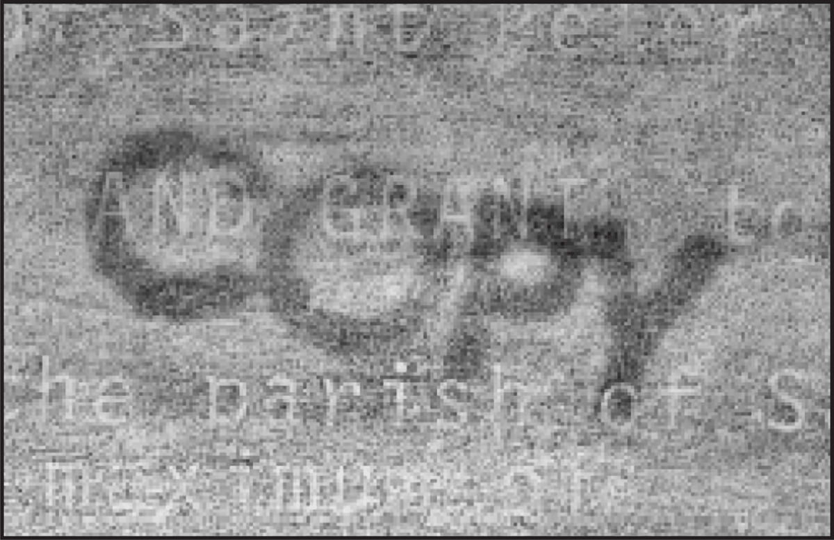
Image 2
First recipient page (Q-1-a) developed by an EDD.
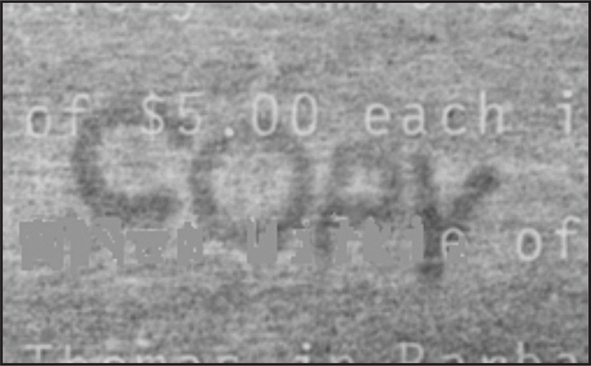
Image 3
Second recipient page (Q-1-b) developed by an EDD.
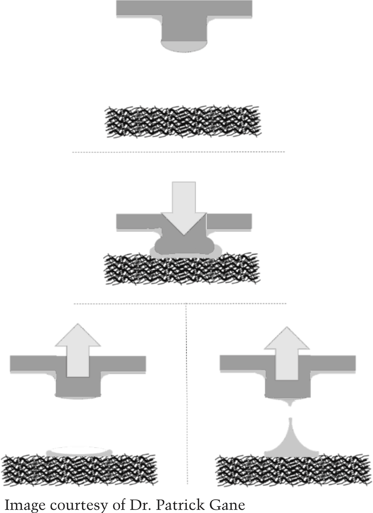
Figure 1
Schematic encompassing the process points 1.-7., illustrating finally the two extremes of ink distribution on the substrate surface depending on ink rheology: note that during the deformation of the elastomer, displaced ink to the outside of the image form can link with reservoir ink surrounding the image profile, in turn leading to high levels of excess ink surrounding the image profile boundary.
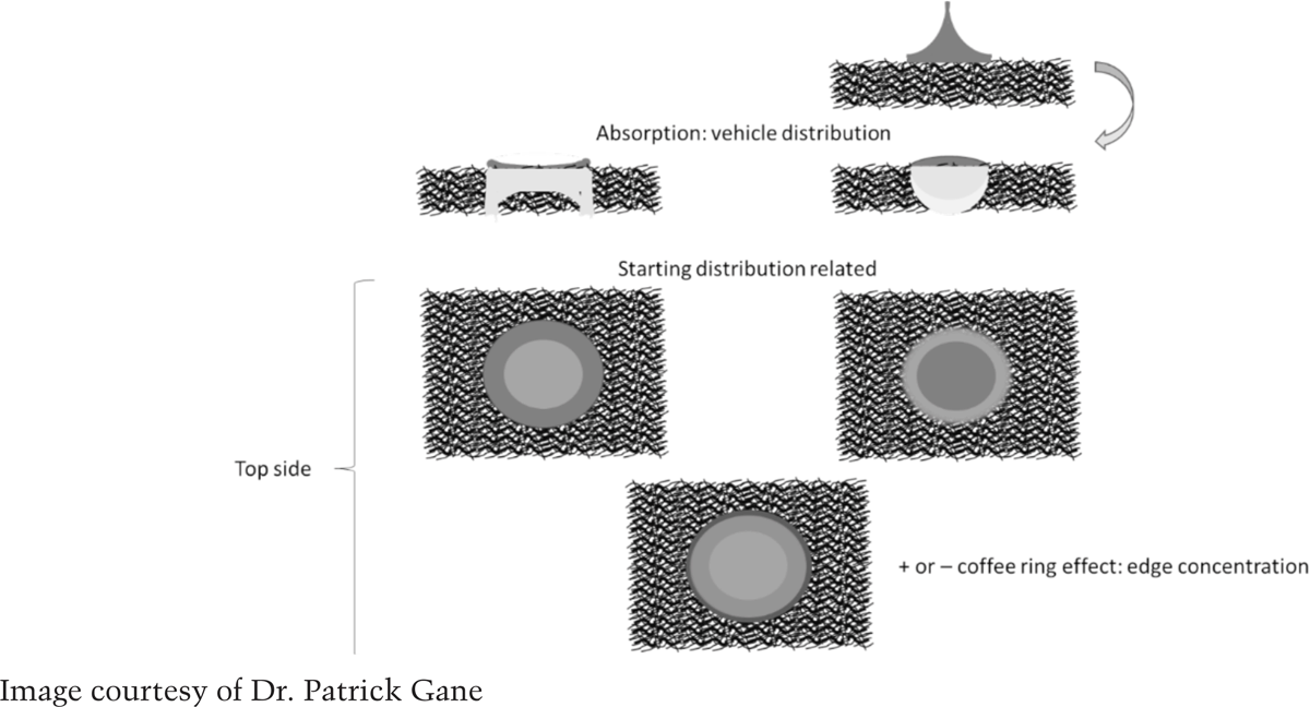
Figure 2
(a) Top side ink distribution after absorption and evaporation, (b) expected strike through properties arising on the reverse side.

Image 4
Originating document with stamped word “COPY.”

Image 5
EDD lift of the recipient page covering the originating document.

Image 6
EDD lift of the recipient page following the originating document.
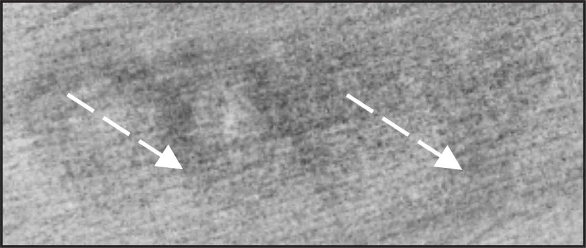
Image 7
Arrows show the repositioning of a recipient page in its downward movement to the right.

Image 8
Illustration of the “tram effect”. (Image printed with the permission of Mr. Shiver.)

Image 9
EDD lift of reverse side of an originating document.

Image 10
Originating document.
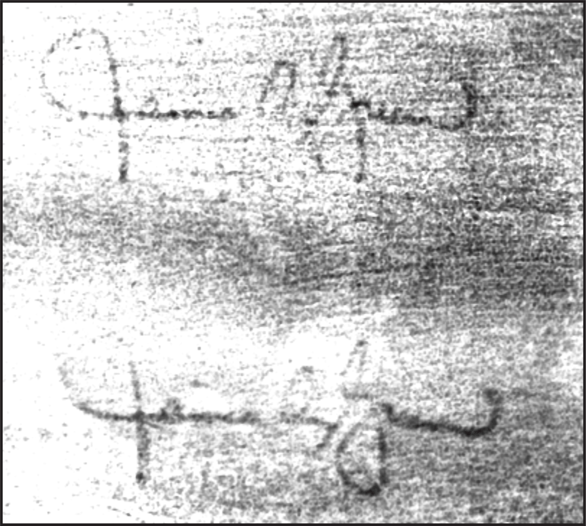
Image 11
EDD lift from the originating document.

Image 12
Originating document with ball point pen signatures.
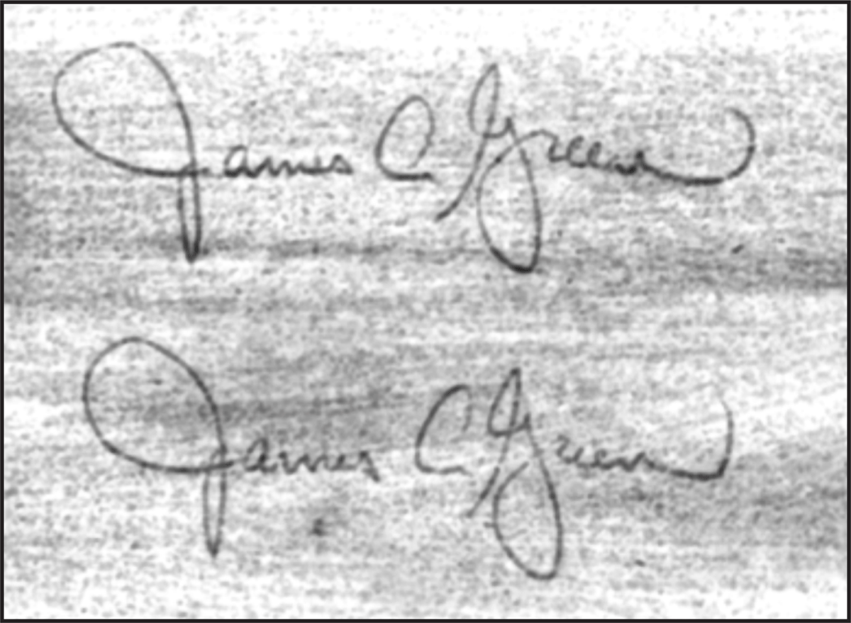
Image 13
EDD lift of indentations penned signatures in Image 12.