

Figure 1
Photo of a typical image set for a CR-80 (credit card) sized ribbon.
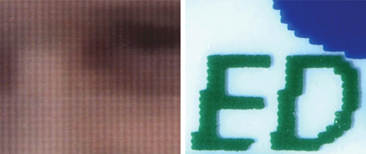
Figure 2
(Left) A magnified image of D2T2. (Right) A magnified image of TMT.
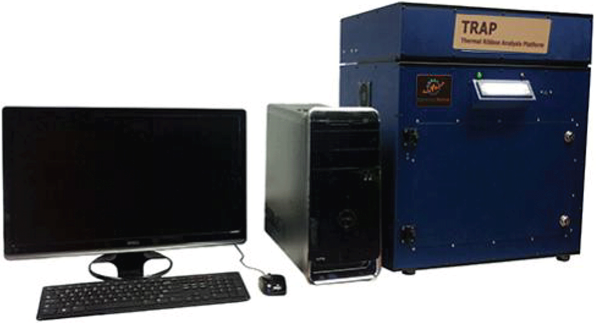
Figure 3
The TRAP system components.
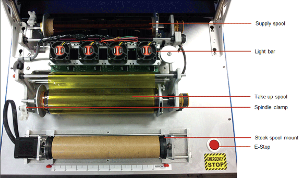
Figure 4
The TRAP spool configuration.
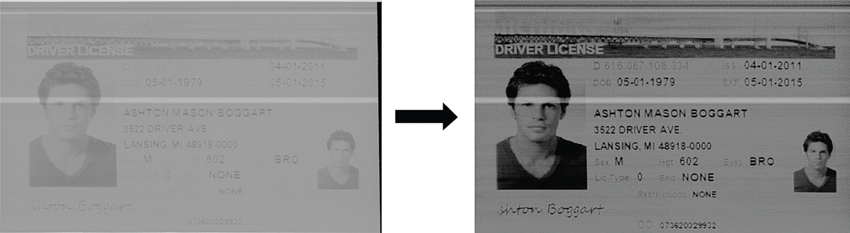
Figure 5
Raw, grayscale image and enhanced, processed image (cyan panel).
Table 1
A description of the ribbons used during the validation testing.
| Accuracy | ||
| Description | Number of Colors | Size |
| A CMY thermal ribbon | 3 | Photo (3.75” high) |
| A CMYO thermal ribbon | 4 | Letter (8.5” high) |
| A CMYKO thermal ribbon | 5 | CR-80 (2.125” high) |
| Repeatability | ||
| Description | Number of Colors | Size |
| A CMY thermal ribbon | 3 | Photo (4.25” high) |
| Intermediate Precision | ||
| Description | Number of Colors | Size |
| A CMYKK thermal ribbon | 5 | CR-80 (2.125” high) |
| Robustness | ||
| Description | Number of Colors | Size |
| A CMYO thermal ribbon | 4 | Letter (8.5” high) |
| A CMYK thermal ribbon | 4 | Letter (8.5” high) |
| A CMYKO thermal ribbon | 5 | CR-80 (2.125” high) |
| A CMYKK sized thermal ribbon | 5 | CR-80 (2.125” high) |
| A silver foil transfer ribbon | 1 | CR-80 (2.125” high) |
| A black label maker thermal ribbon | 1 | 0.75” high |
| A single row typewriter ribbon | 1 | 0.25” high |
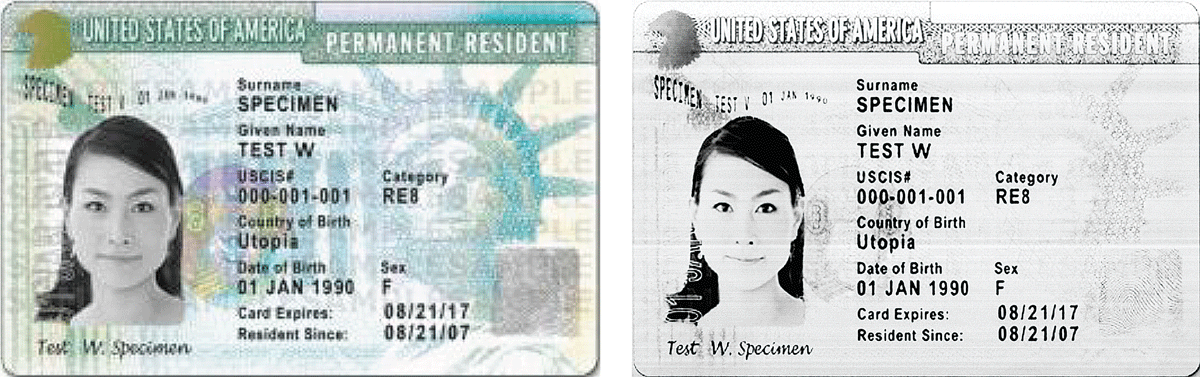
Figure 6
Original card image (left) and the enhanced cyan scan from the TRAP (right).