
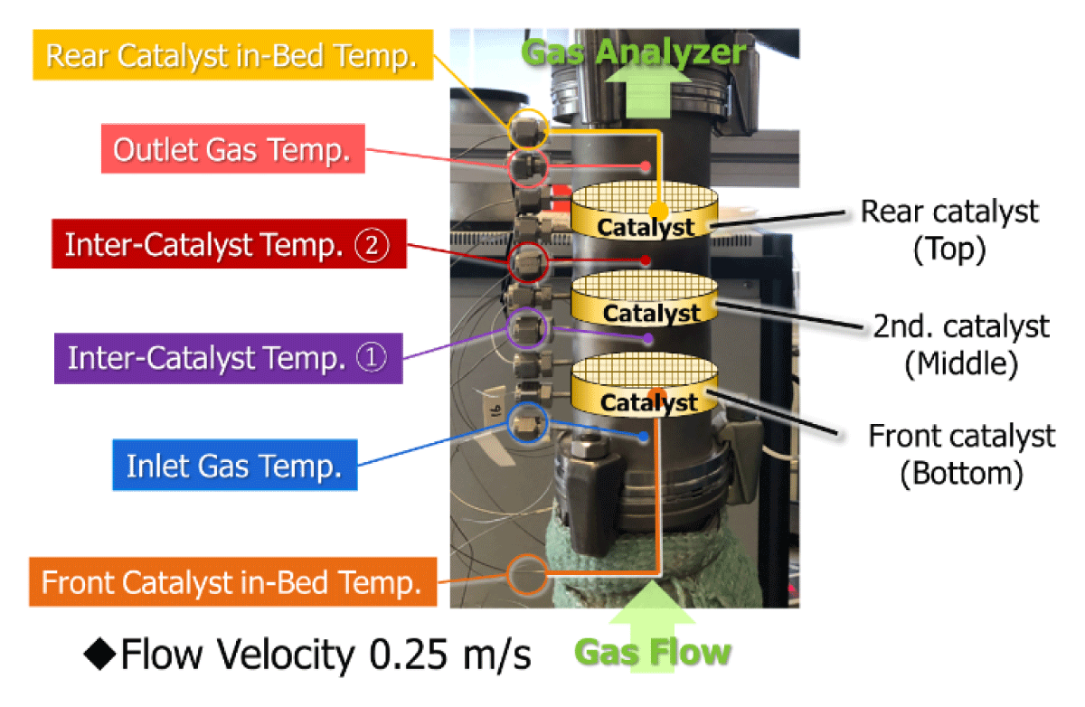
Figure 1
Setup of the multi-stage catalyst system installed in REKO-1.
Table 1
Detailed configuration of catalysts used in each layer.
| #01 | #02 | #03 | #04 | #05 | #06 | |
|---|---|---|---|---|---|---|
| Rear catalyst layer | Pt(1.0) Fe(0.25) /CZY-L | Pt(1.0) Fe(0.25) /CZY-L | Pt(2.0) Fe(0.5) /AI2O3 | Pt(2.0) Fe(0.5) /AI2O3 | Pt(2.0) Fe(0.5) /AI2O3 | Pt(1.0) Fe(0.25) /CZY-L |
| Thickness | 10 mm | 10 mm | 5 mm | 5 mm | 5 mm | 10 mm |
| Middle catalyst layer | Pt(0.015) FeCO.985) /AI2O3 | Pt(0.015) Fe(0.985) /CZY-L | Fe(6.0) /AI2O3 | Pt(0.015) FeCO.985) /AI2O3 | Fe(6.0) /AI2O3 | Pt(0.015) Fe(0.985) /AI2O3 [*1] |
| Thickness | 5 mm | 5 mm | 5 mm | 5 mm | 5 mm | 5 mm |
| Front catalyst layer | Pt(0.001) Fe(O.999) /AI2O3 | Pt(0.001) Fe(0.999) /CZY-L | Pt(0.001) Fe(0.999) /AI2O3 | Fe(6.0) /AI2O3 | Pt(0.015) Fe(0.985) /AI2O3 | Pt(0.001) Fe(0.999) /AI2O3 [*1] |
| Thickness | 5 mm | 5 mm | 5 mm | 5 mm | 5 mm | 5 mm |
[i] *1 Prepared by the sequential impregnation method, with Pt followed by Fe. Other Pt-Fe catalysts not marked with a symbol were prepared by the simultaneous co-impregnation method.
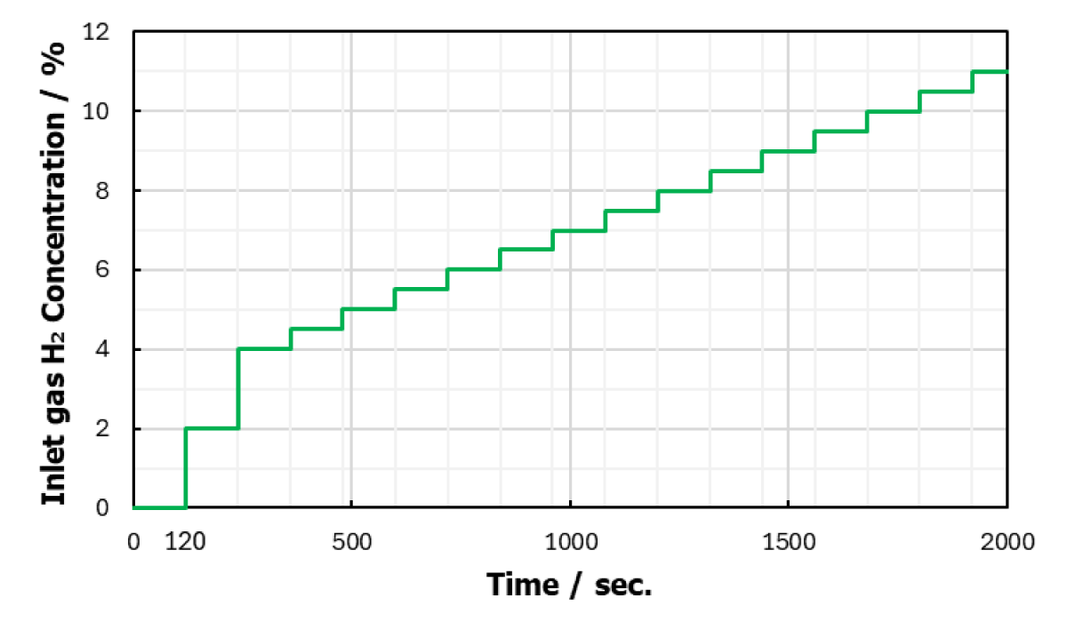
Figure 2
Variation in inlet hydrogen gas concentration.
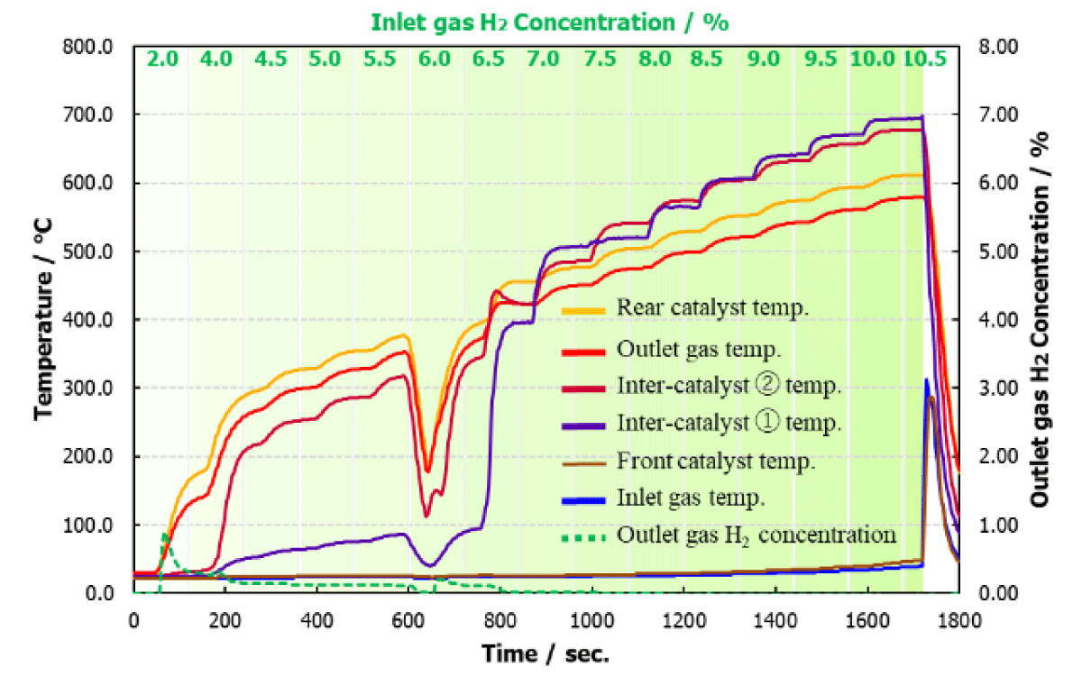
Figure 3
Multi-stage catalyst set #01.
Configuration using Al2O3 for both the Middle and Front layers.
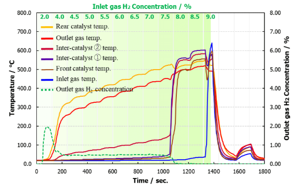
Figure 4
Multi-stage catalyst set #02.
Configuration using CZY-L for both the Middle and Front layers.
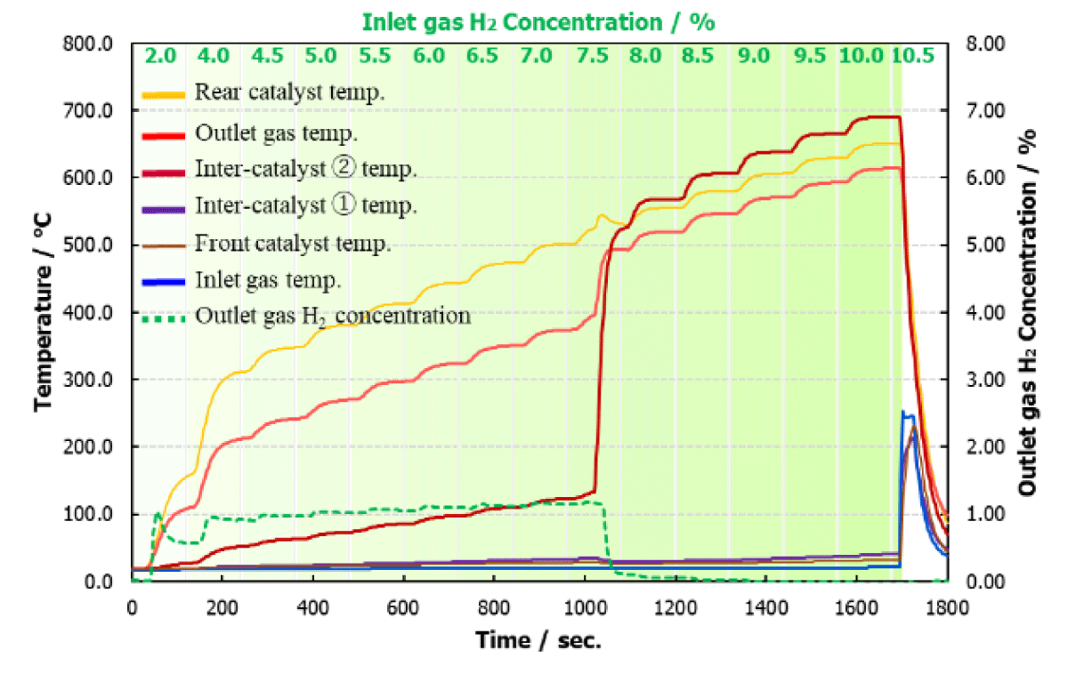
Figure 5
Multi-stage catalyst set #03.
Configuration using Fe-only catalysts in the Middle layer.
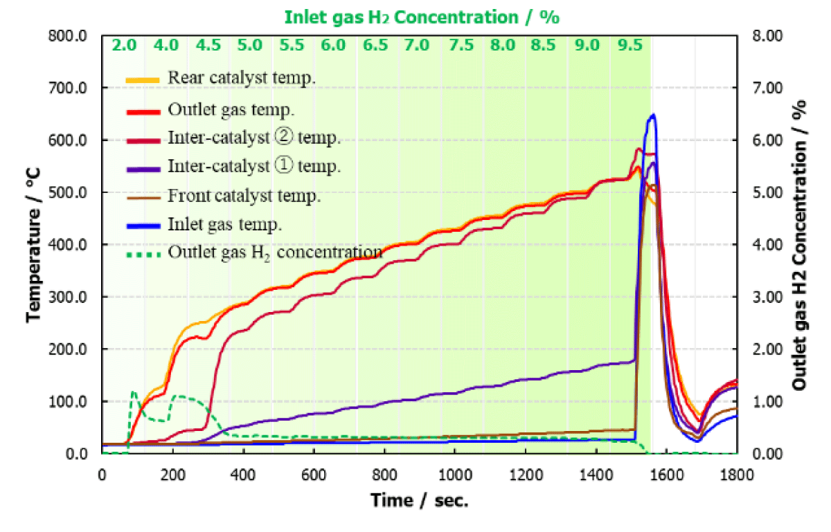
Figure 6
Multi-stage catalyst set #04.
Configuration with Fe-only catalysts placed in the Front layer.
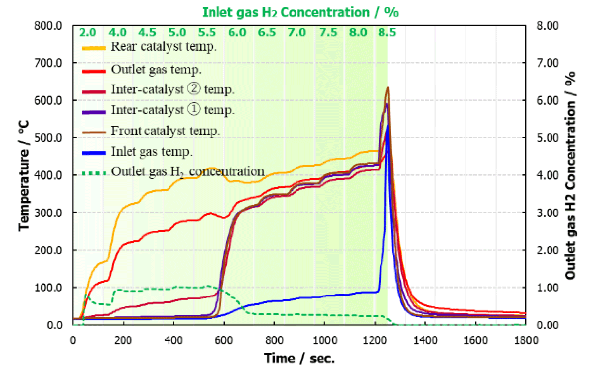
Figure 7
Multi-stage catalyst set #05.
Configuration with Fe-only catalysts placed in the Middle layer.
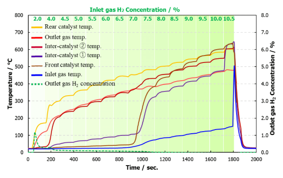
Figure 8
Multi-stage catalyst set #06.
Configuration using sequentially impregnated catalysts in the Middle and Front layers.
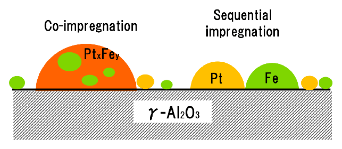
Figure 9
Particle models of Pt-Fe catalysts prepared by different impregnation methods.