
1. Introduction
Ensuring safety is a critical requirement for the widespread adoption of hydrogen technologies. Hydrogen has a wide flammability range in air, from 4 to 75 vol% (Miyake, 1997). Improper handling can result in a significant risk of fire or explosion (Hansen and Hansen, 2023). Particularly, passive safety measures to prepare for potential leakage are essential at every stage of LH2 management, including storage, transportation, and utilization, due to its high energy density.
One promising approach is the passive autocatalytic recombiner (PAR), which reduces hydrogen concentration by catalytically recombining hydrogen with oxygen to produce water (Tanaka et al., 2025a; Reinecke et al., 2004). PARs operate without any external power. Hydrogen naturally contacts the catalyst surface, reacts with oxygen, and generates steam along with heat (Malakhov et al., 2022).
Since the Fukushima Daiichi nuclear accident, PARs have been widely implemented in Japan as a safety measure. They have been adopted at a broad range of facilities, including the Kashiwazaki-Kariwa and Genkai nuclear power plants. However, in hydrogen production facilities, the operating environments vary significantly depending on conditions such as atmospheric pressure, outdoor installation, and localized space. As a result, PAR adoption has been limited to only a small number of facilities.
Since liquefied hydrogen (LH2) has an energy density 800 times higher than that of gaseous hydrogen at standard state, the hydrogen oxidation reaction can proceed rapidly during actual PAR operation when the flow rate of leaked LH2 is high or the hydrogen concentration increases (Jäkel et al., 2014). In high-velocity LH2 leakage scenarios, the risks of catalyst thermal runaway due to rapid reaction heat and subsequent gas-phase ignition remain major challenges (Payot et al., 2012; Chakraborty et al., 2017).
Conventional PAR designs often assume relatively mild operating conditions (Kelm et al., 2009). As a result, their thermal stability and ability to control reaction behavior under extreme conditions have not been fully investigated.
This study aims to clarify the reaction behavior and the temperature-rise mechanism of hydrogen oxidation catalysts under severe conditions, including high flow rates, high hydrogen concentrations, and high energy densities. It systematically evaluates how differences in precious metal loading and catalyst support materials affect ignition concentrations and temperature profiles in multilayer catalyst configurations. It also analyzes the effects of heat conduction and radiation between catalyst segments on spontaneous activation.
The goal is to derive design guidelines for catalyst configurations that prevent reaction heat from becoming a new ignition source. These findings are expected to contribute to the development of high-performance and reliable PAR technologies that enhance the safety of hydrogen utilization.
2. Test Conditions
2.1. Catalyst preparation
The hydrogen oxidation catalysts used in this study were prepared by supporting precious metals (Pt) and Fe on catalyst supports. Two types of supports were employed: a cerium–zirconium–yttrium composite oxide (Ce0.49Zr0.46Y0.05O2-δ, hereafter referred to as CZY), developed by Daihatsu Motor Co., Ltd for automotive applications, and γ-Al2O3. Prior to precious metal loading, the supports were coated onto a designated base material (honeycomb-structured ceramics) using a slurry coating method, followed by calcination in air to ensure thermal stability (Figure 1).
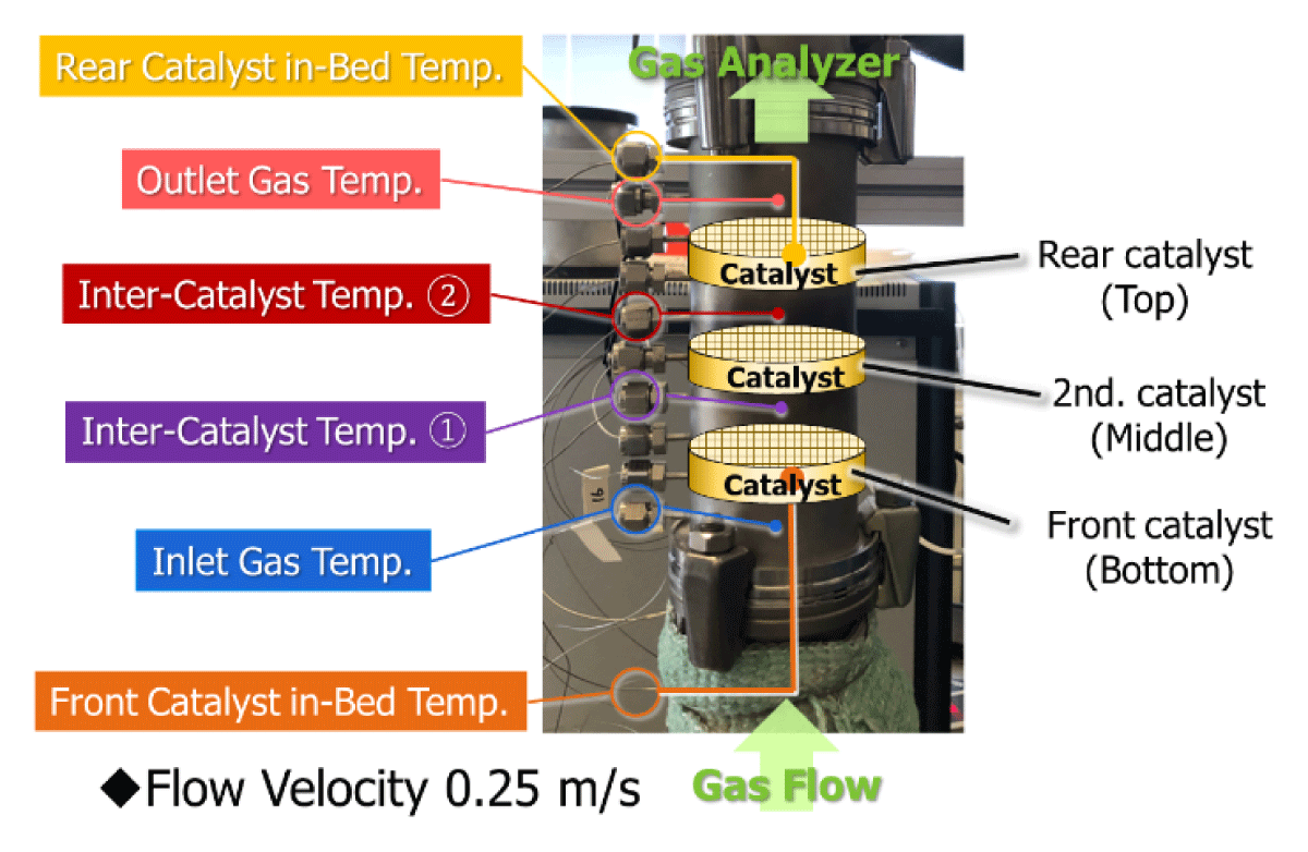
Figure 1
Setup of the multi-stage catalyst system installed in REKO-1.
For CZY, the coated support was calcined in air at 1000°C for 5 hours, resulting in a specific surface area (SSA) of 26.3 m–2 ∙ g–1. This post-treatment material is referred to as CZY-L. The SSA of γ-Al2O3 was 138.6 m–2 ∙ g–1, while that of untreated CZY was 109.1 m–2 ∙ g–1. Precious metal loading was carried out by dropwise addition of dinitrodiammine platinum nitrate [Pt(NO2)2(NH3)2] and ferric nitrate [Fe(NO3)3 ∙ 9H2O] onto the supports. The catalysts were then dried and calcined to complete the preparation process. The specifications of the supported metals are shown in Table 1. The values in parentheses indicate the weight percentages of the supported metals. The precious metal concentrations were varied according to the configuration of each catalyst layer.
Table 1
Detailed configuration of catalysts used in each layer.
| #01 | #02 | #03 | #04 | #05 | #06 | |
|---|---|---|---|---|---|---|
| Rear catalyst layer | Pt(1.0) Fe(0.25) /CZY-L | Pt(1.0) Fe(0.25) /CZY-L | Pt(2.0) Fe(0.5) /AI2O3 | Pt(2.0) Fe(0.5) /AI2O3 | Pt(2.0) Fe(0.5) /AI2O3 | Pt(1.0) Fe(0.25) /CZY-L |
| Thickness | 10 mm | 10 mm | 5 mm | 5 mm | 5 mm | 10 mm |
| Middle catalyst layer | Pt(0.015) FeCO.985) /AI2O3 | Pt(0.015) Fe(0.985) /CZY-L | Fe(6.0) /AI2O3 | Pt(0.015) FeCO.985) /AI2O3 | Fe(6.0) /AI2O3 | Pt(0.015) Fe(0.985) /AI2O3 [*1] |
| Thickness | 5 mm | 5 mm | 5 mm | 5 mm | 5 mm | 5 mm |
| Front catalyst layer | Pt(0.001) Fe(O.999) /AI2O3 | Pt(0.001) Fe(0.999) /CZY-L | Pt(0.001) Fe(0.999) /AI2O3 | Fe(6.0) /AI2O3 | Pt(0.015) Fe(0.985) /AI2O3 | Pt(0.001) Fe(0.999) /AI2O3 [*1] |
| Thickness | 5 mm | 5 mm | 5 mm | 5 mm | 5 mm | 5 mm |
[i] *1 Prepared by the sequential impregnation method, with Pt followed by Fe. Other Pt-Fe catalysts not marked with a symbol were prepared by the simultaneous co-impregnation method.
2.2. Experimental setup and environment
Catalyst performance evaluation was conducted using the REKO-1 test facility installed at Forschungszentrum Jülich in Germany (Reinecke et al., 2011). REKO-1 introduces hydrogen and air (oxygen) from the bottom of a stainless-steel cylindrical chamber with a 70 mm inner diameter. This generates an upward flow simulating a hydrogen leakage environment. We developed a reactor system with three layers of vertically stacked honeycomb catalysts, installed it inside the chamber, and conducted tests.
The honeycomb catalysts have a diameter of 65 mm, a thickness of either 5 mm or 10 mm, and a cell density of 30 cpsi (cells per square inch). They were arranged in three layers with a 20 mm spacing. To distinguish catalyst thermal runaway from gas-phase self-ignition, temperatures were monitored independently at the catalyst beds and in the gas phase. Thermocouples inserted into or near each catalyst layer were used to evaluate local heat generation caused by catalytic hydrogen oxidation, whereas separate thermocouples placed in the inlet and outlet gas streams were used to detect rapid gas-phase heating.
For the evaluation of catalytic activity, a thermal conductivity detector (TCD) and a paramagnetic oxygen analyzer were installed at the gas outlet downstream of the catalyst to monitor hydrogen and oxygen concentrations, respectively.
The test gases were introduced at room temperature, and the hydrogen concentration in the gas mixture was gradually increased to monitor the catalyst’s reaction response and temperature rise behavior.
2.3 Catalytic activity evaluation
In the activity evaluation, the hydrogen concentration was incrementally increased every two minutes under atmospheric conditions, while monitoring the temperature responses of each catalyst layer and the changes in hydrogen concentrations in the exhaust gas (Figure 2). The hydrogen flow rate was adjusted according to the mixing ratio with air, and the gas flow velocity was kept constant at 0.25 m ∙ g–1. The reaction proceeded in an upward direction from the bottom of the reactor, and the hydrogen concentration at which each catalyst layer initiated activation, along with the corresponding temperature rise trends, was carefully recorded. This condition was not intended to reproduce the near-field jet velocity immediately after LH2 leakage. Instead, it was selected as a controlled forced-flow condition representative of hydrogen-containing gas entering a PAR catalyst section after dispersion and air entrainment. At this velocity, the residence time in each honeycomb segment was very short, approximately 0.02 s for a 5 mm catalyst and 0.04 s for a 10 mm catalyst. Furthermore, it should be noted that these values are based on the inlet condition at room temperature. In reality, the intense reaction heat of hydrogen oxidation causes rapid gas expansion, which locally accelerates the flow velocity and makes the actual residence time even shorter. This makes the condition extremely demanding in terms of reaction completion and heat management (Krenz et al., 2025). The velocity was therefore kept constant in order to isolate the effects of hydrogen concentration, catalyst composition, and layer arrangement on temperature rise and self-ignition behavior.
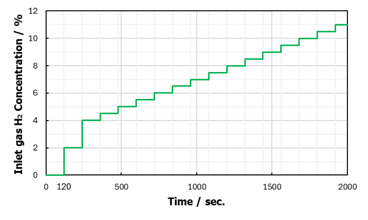
Figure 2
Variation in inlet hydrogen gas concentration.
In this study, the onset of self-ignition was defined as the point when the inlet gas temperature exceeded 200°C and showed a sharp, nearly vertical increase. It should be noted that when ignition occurs spontaneously during the experiment, it produces a sound resembling that of a low-pitched woodwind instrument and causes the gas pipe to vibrate, making it easily recognizable. Our previous research demonstrated that self-ignition in multilayer catalysts originates at the chamber inlet side (Tanaka et al., 2025b). To address this issue, this research evaluated the safety of a multi-layer catalyst configuration in which the precious metal concentration in the front layer was minimized to promote a gradual and controlled progression of the oxidation reaction. It should be noted that direct optical flame visualization was not performed in this study. Therefore, the term self-ignition refers to an operationally defined gas-phase ignition event based on the independent gas-temperature measurement and its sharp transient behavior.
Through this procedure, the minimum hydrogen concentration at which spontaneous ignition occurred for each catalyst configuration was clearly determined, aiming to establish safety design guidelines for catalyst structures.
3. Results and Discussion
3.1. Comparison of reaction dispersion based on identical catalyst structures with different support designs (Al2O3 vs. CZY-L)
In Set #01, the rear layer contained the highest platinum loading (1.0 wt%) and the greatest thickness (10 mm), making it the most reactive component within the structure. The temperature of the rear layer began to increase rapidly at approximately 100 seconds, corresponding to a hydrogen concentration of 2.0%, and was accompanied by a sharp decrease in outlet hydrogen concentration. This indicates that hydrogen oxidation initiated predominantly in the rear layer. In contrast, the middle (2nd) layer exhibited a delayed temperature increase, suggesting that its activation was thermally induced by the reaction heat generated in the rear layer, rather than by its own intrinsic catalytic activity (Figure 3).
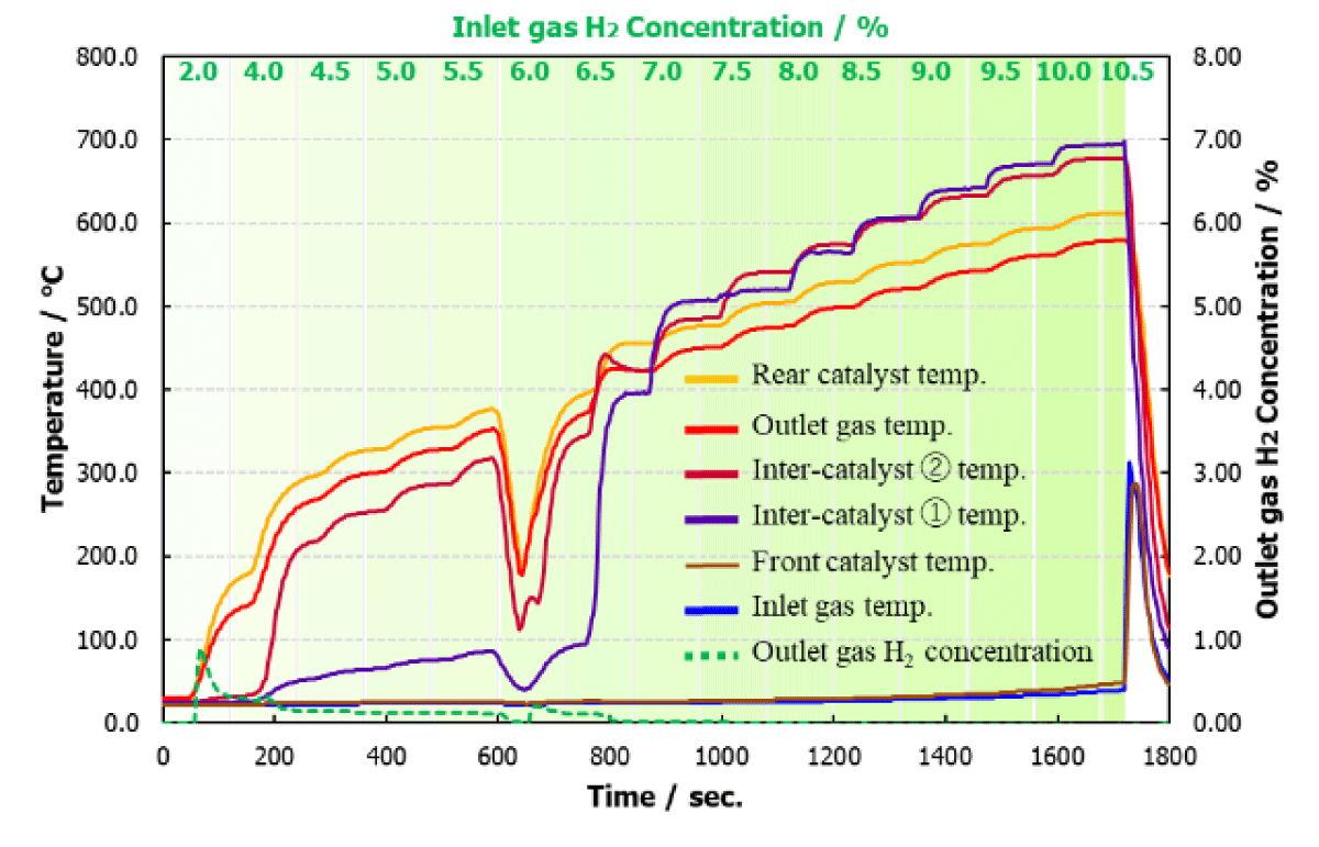
Figure 3
Multi-stage catalyst set #01.
Configuration using Al2O3 for both the Middle and Front layers.
On the other hand, although Set #02 used the same platinum loading and layer thickness in the rear, it utilized CZY-L as the support in all three catalyst layers. In this case, while the rear layer activated at 100 seconds, the middle and front layers were activated later, around 1000 and 1100 seconds, respectively (Figure 4).
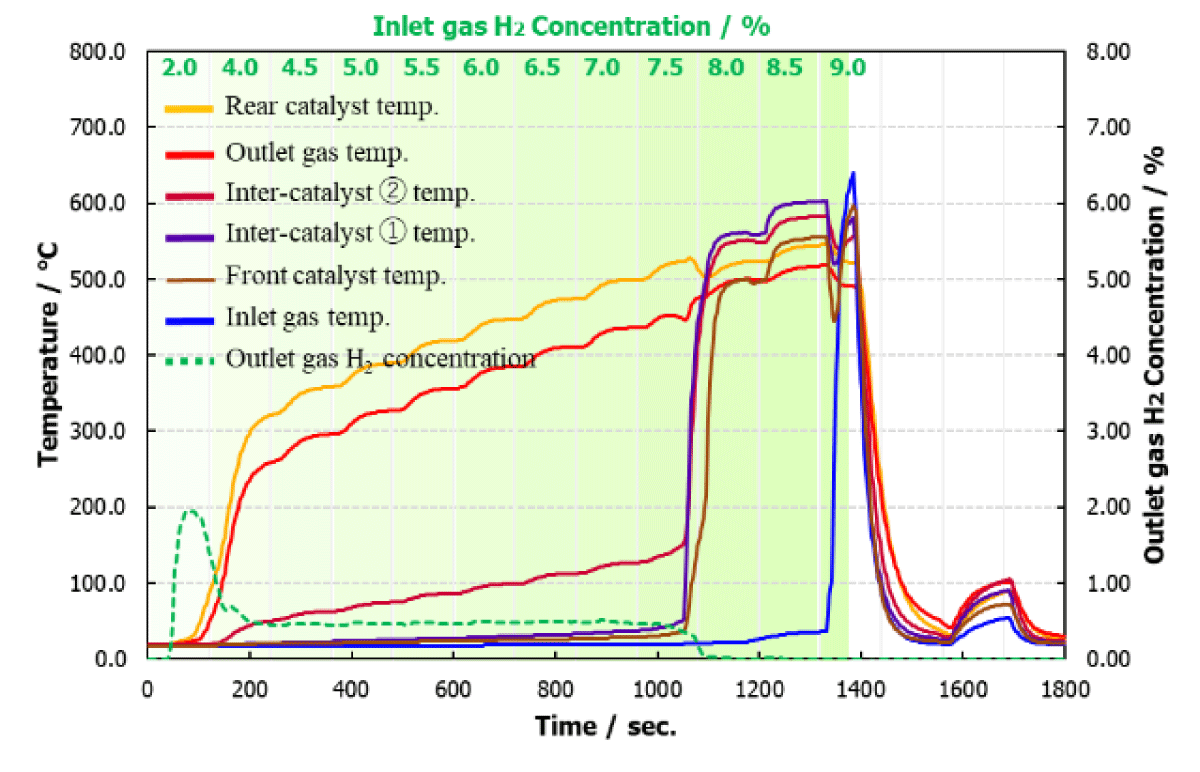
Figure 4
Multi-stage catalyst set #02.
Configuration using CZY-L for both the Middle and Front layers.
It has been confirmed that the specific surface area of CZY-L (26.3 m–2 ∙ g–1) is smaller than that of Al2O3 (138.6 m–2 ∙ g–1). At the same metal loading, a larger specific surface area means more effective active sites directly involved in the reaction. When reaction heat from the downstream rear layer propagates upstream, the Al2O3-based middle layer quickly activates. It initiates the hydrogen oxidation reaction at a relatively low thermal energy level. Thus, it can be inferred that the middle layer begins to share the reaction load of the entire system at an early stage. In contrast, in the CZY-L configuration, unreacted high-concentration hydrogen is considered to pose a direct load on the front layer. Consequently, high metal dispersion was demonstrated to promote a smooth, stepwise transition of the reaction zone.
3.2. Verification of a stepwise reaction configuration with rear-dominant layer and Fe-assisted middle layer
In this experiment, the rear catalyst layer was the first to activate at approximately 200 seconds, corresponding to a hydrogen concentration of 2.0%. This activation was marked by a sharp temperature increase and a significant drop in outlet hydrogen concentration, indicating that hydrogen oxidation was initiated predominantly in the rear layer. It served as the primary reaction zone and the main source of heat generation during the early stages of the experiment.
The middle layer, which contained only Fe and no precious metals, was initially assumed to function as a thermally inert buffer without catalytic activity. However, the experimental data revealed a distinct secondary event: at around 1000 seconds, the middle layer exhibited a sharp rise in temperature, accompanied by a further notable decrease in outlet hydrogen concentration. This simultaneous change suggests that the Fe-loaded middle layer contributed to hydrogen oxidation under elevated temperature conditions (Figure 5).
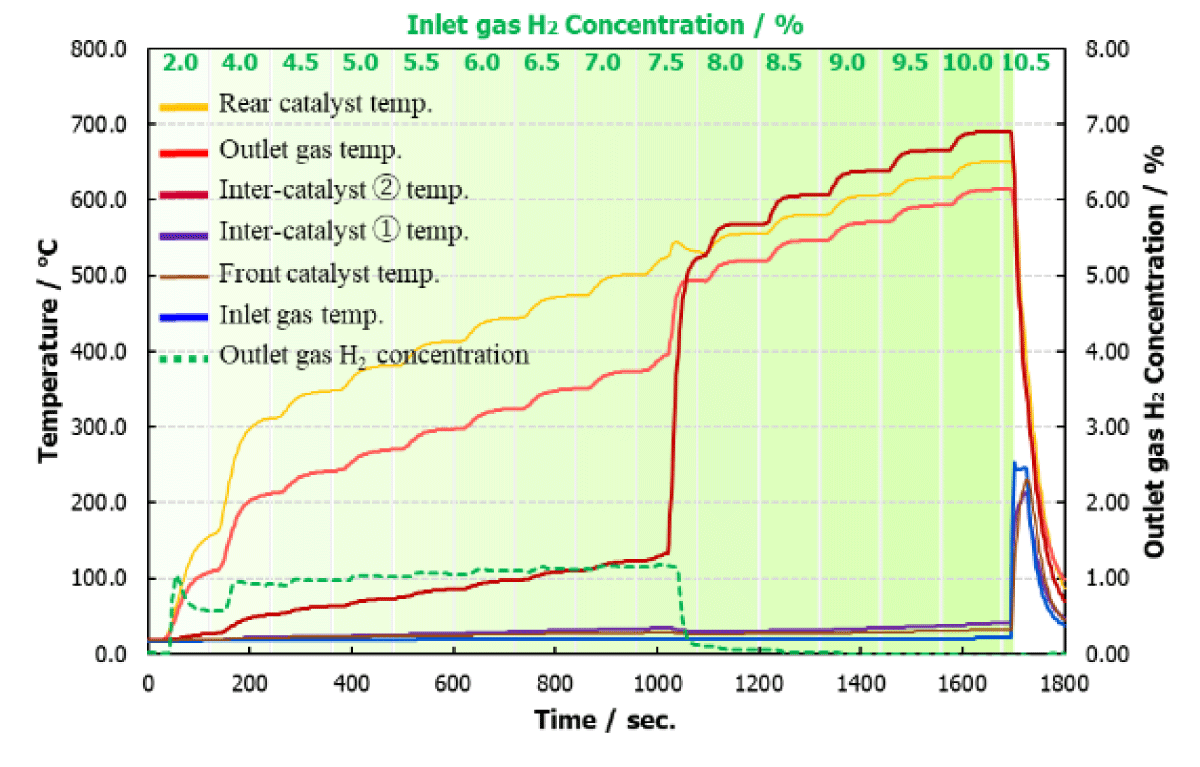
Figure 5
Multi-stage catalyst set #03.
Configuration using Fe-only catalysts in the Middle layer.
A possible mechanism is that the heat generated in the rear layer gradually raised the temperature of the entire system. Once the middle layer reached a critical threshold, Fe may have started to participate in thermochemical redox reactions. While Fe has limited activity at low temperatures, it can act as an oxygen carrier under high-temperature and hydrogen-rich conditions (Gamisch et al., 2022). Through reversible oxidation and reduction, Fe may have supplied reactive oxygen to support hydrogen oxidation. In this way, Fe could have played a supplemental role in sustaining the reaction without the use of precious metals.
3.3. The influence of inlet-side catalyst composition on hydrogen oxidation and auto-ignition behavior
To clarify the influence of the placement of Pt–Fe composite catalysts and Fe-only catalysts on hydrogen oxidation behavior and auto-ignition concentration, catalyst configurations in Sets #04 and #05 were compared. The two sets differ only in the placement of catalysts between the front and middle positions.
In the temperature profiles, Set #04 showed dominant activity in the rear layer, while temperature rise in the front layer was suppressed until the final stage (Figure 6). In contrast, Set #05 exhibited a stepwise temperature increase not only in the rear but also in the middle and front layer (Figure 7). Notably, the front layer showed a rapid temperature rise at hydrogen concentrations above 6.0%. As a result, the auto-ignition concentration was 9.5% in Set #04 and 8.5% in Set #05. This indicates that placing a Pt–Fe composite catalyst with a high noble metal loading at the front position tends to promote earlier reaction initiation as hydrogen concentration increases. In Set #05, the front layer acted as an active site and caused a sharp temperature increase. This behavior is also supported by comparison with Set #03. On the other hand, in Set #04, the front layer consisting of Fe(6.0)/Al2O3 showed little to no activity even under high hydrogen concentration. As a result, heat transfer was suppressed near the inlet, and the reaction mainly progressed toward the outlet side.
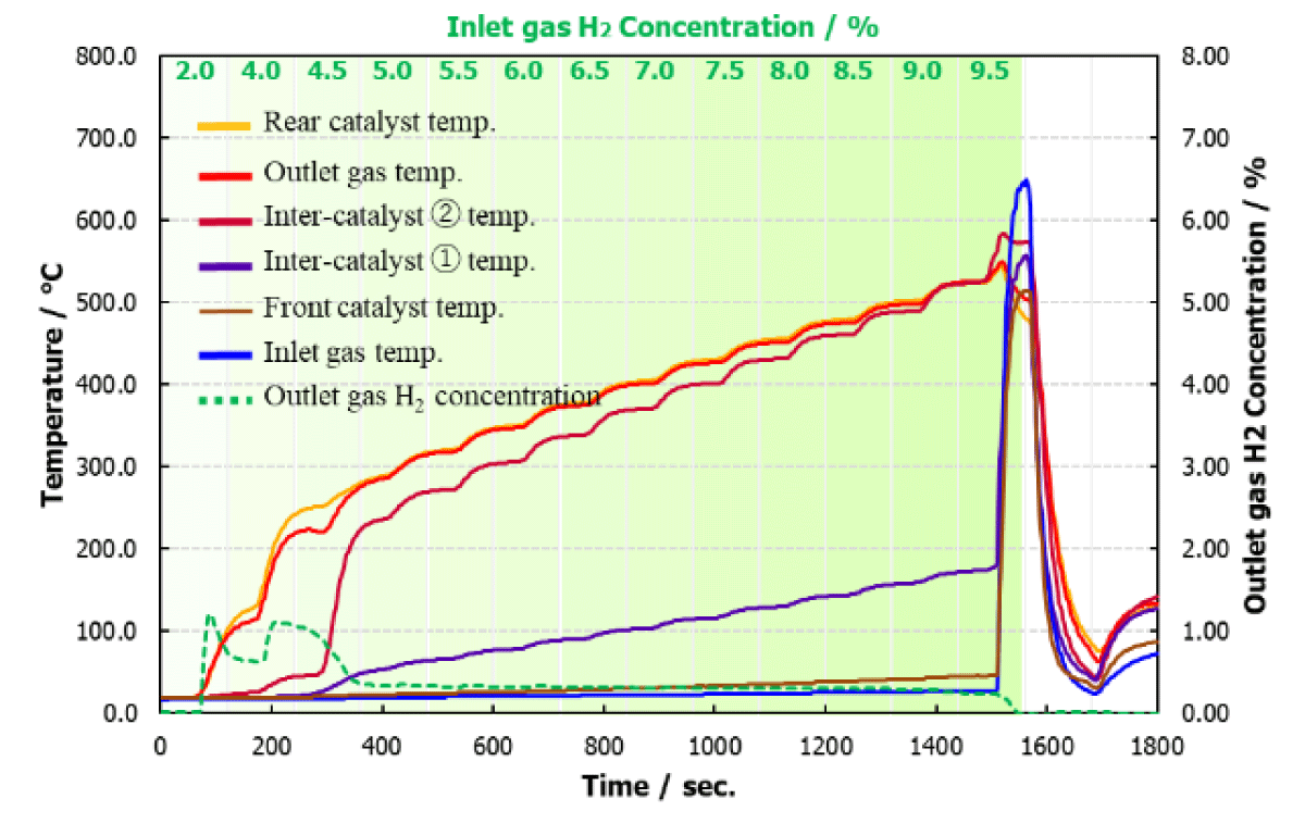
Figure 6
Multi-stage catalyst set #04.
Configuration with Fe-only catalysts placed in the Front layer.
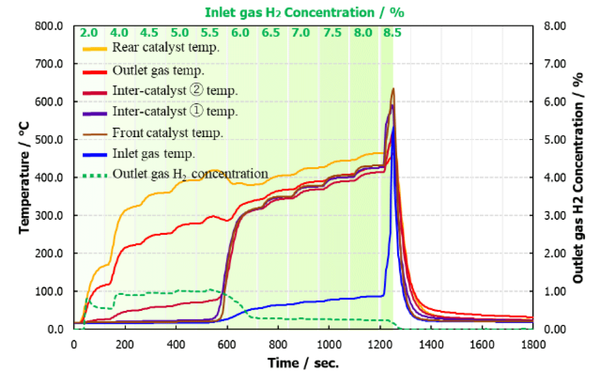
Figure 7
Multi-stage catalyst set #05.
Configuration with Fe-only catalysts placed in the Middle layer.
These results demonstrate that not only the type and loading of the catalyst but also its placement significantly affects the auto-ignition behavior. For designs aiming to suppress auto-ignition, placing highly active catalysts near the inlet may pose a risk. Conversely, to promote early ignition, placing Pt–Fe composite catalysts with high metal loading near the inlet is effective.
3.4. Effect of different impregnation methods (comparison with 2023 results)
In the 2023 experiments, Set #06 used a sequential impregnation technique for the middle and front layers, wherein Pt (0.015 wt% and 0.001 wt%, respectively) was first impregnated and calcined, followed by dropwise addition of Fe solution (0.985 wt% and 0.999 wt%). The rear layer, composed of Pt–Fe/CZY-L (10 mm thick), was the first to activate at approximately 40 seconds, marked by a rapid temperature increase. This behavior was attributed to the cooperative effect of Pt and Fe. Subsequent temperature rises in the middle and front layers at 400 seconds (H2: 4.0%) and 700 seconds (H2: 7.0%), respectively, indicated a clearly staged, spatially distributed reaction progression across all three layers (Figure 8).
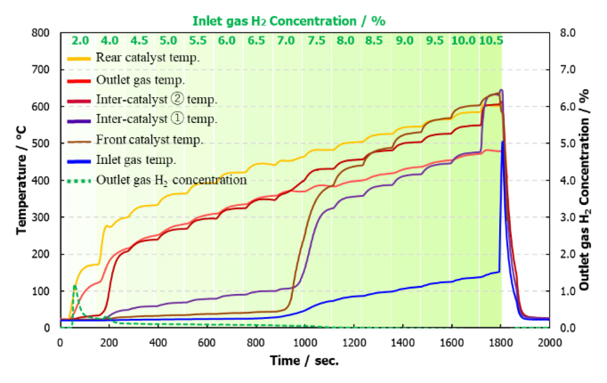
Figure 8
Multi-stage catalyst set #06.
Configuration using sequentially impregnated catalysts in the Middle and Front layers.
In contrast, Set #01 utilized a co-impregnation method in which Pt and Fe were simultaneously supported from a mixed solution onto all three layers, with Al2O3 as the support. This configuration led to early activation of the rear layer at a hydrogen concentration of 2.0%, followed by limited thermal response in the middle layer and negligible activity in the front layer. The reaction predominantly occurred within the rear layer, indicating a highly localized and concentrated reaction pattern.
Inagawa et al. (2023) reported that alloying Pt with Fe promotes the rapid switching of adsorbed species on Pt nanoparticle surfaces. This effect strongly accelerates both oxidation and reduction reactions. Although this alloy configuration exhibits extremely high catalytic activity, it inherently induces excessive localized heat generation when exposed to high-flow, high-concentration hydrogen streams. Furthermore, Kim et al. (2012) reported that the order of Fe introduction in PtPd/Al2O3 oxidation catalysts strongly affects the interactions among noble metal particles, iron oxide species, and the Al2O3 support. In particular, Fe introduced after noble metal loading promoted the formation of iron oxide species with high oxygen mobility near the noble metal phase, whereas Fe introduced before noble metal loading preferentially interacted with Al2O3 to form Fe/Al2O3, resulting in a decrease in surface area.
Based on these findings, the co-impregnated Pt–Fe catalyst in the present study is considered to favor closer contact or stronger interaction between Pt and Fe species, possibly leading to an alloy-like or highly interacting state (Ma et al., 2025). In contrast, sequential impregnation may allow Pt and Fe species to remain more spatially separated, enabling Fe oxide species to act as oxygen donors or redox promoters during hydrogen oxidation (Figure 9).
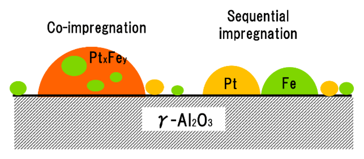
Figure 9
Particle models of Pt-Fe catalysts prepared by different impregnation methods.
4. Conclusion
In this study, we investigated the thermal behavior and auto-ignition risk of hydrogen oxidation under harsh conditions, including high hydrogen concentration and demanding forced-flow conditions. Specifically, we evaluated the reaction controllability of multilayer hydrogen oxidation catalysts.
The effects of noble metal loading, support material, and metal species (Pt, Fe) in each catalyst position were compared in terms of their influence on reaction initiation concentration and temperature-rise behavior.
In configurations where the reaction concentrated in the rear layer, significant localized temperature rise was observed. In such cases, the reaction heat did not propagate to the downstream catalysts, and the auto-ignition concentration tended to decrease. In contrast, when a Pt–Fe composite catalyst was placed at the front, the reaction progressed stepwise toward the upstream side. Under high hydrogen concentrations, this led to a rapid temperature rise and further reduction in ignition threshold.
On the other hand, when an Fe-only catalyst was placed at the front, the reaction did not easily proceed even under high hydrogen concentrations. As a result, the reaction remained limited to the rear layer, and the auto-ignition concentration remained relatively high.
Furthermore, a comparison between sequential and co-impregnation methods for Pt and Fe revealed that the sequential method enabled Fe to function more effectively as an oxygen donor. This led to a more controlled heat distribution and progressive reaction development.
These findings demonstrate that, to safely process high-concentration hydrogen while avoiding auto-ignition, it is essential to control not only the catalyst composition and impregnation method but also the spatial arrangement of catalysts. Configurations that allow stepwise reaction progression and suppress localized heating are effective in enhancing the reliability of passive safety mechanisms inherent to PAR systems.
The knowledge obtained in this study provides a foundation for the design of thermally stable and safe PARs in real-world applications. It is expected to contribute to the development of highly reliable catalyst technologies that support the safe implementation of hydrogen systems in future society.
5. Future Outlook
To ensure the safe operation of PARs under high hydrogen concentration and high-flow conditions, it is important to establish techniques for precisely controlling heat generation and reaction distribution within multilayer catalyst systems. To prevent localized overheating and ignition, designing catalyst structures with spatially differentiated functions may be effective.
One potentially useful configuration involves placing a high concentration of precious metals in the rear layer to reliably initiate the initial reaction. In the Middle layer, Fe-only catalysts can be used, which are activated later by the heat generated in the rear layer. Under high-temperature conditions, Fe can function as an oxygen donor or a co-catalyst, contributing to sustained reactivity and effective heat dispersion.
For the front layer, it may be preferable to avoid highly active precious metals. Instead, using materials that only respond under high hydrogen concentrations, such as Fe-only or low-loaded Pt–Fe catalysts, can help suppress sudden temperature rises and reduce the risk of auto-ignition.
Regarding catalyst preparation, previous findings suggest that sequential impregnation of Pt and Fe, rather than co-impregnation on the same support, allows phase separation. This arrangement can enhance the auxiliary function of Fe and may serve as a useful design approach.
In addition, selecting different support materials for each layer based on their thermal and chemical roles can improve spatial control of reaction and heat transfer. For the rear layer, using CZY-L, which has high oxygen storage capacity and heat capacity, can help moderate the initial reaction and absorb heat effectively. In the second layer, Al2O3 can support the thermal activation of Fe. In the front layer, using a support with low thermal conductivity such as SiO2 may slow down heat transfer and delay the onset of reaction. When combined with delayed-response catalysts like Fe-only or low-loaded Pt–Fe, this design may further suppress the risk of auto-ignition.
Such a stepwise and functionally optimized multilayer catalyst structure could be a promising strategy for achieving reliable reaction initiation, controlled reaction progression, and suppression of heat concentration simultaneously.
Acknowledgements
A part of this work was the results of the international joint project “Towards Safe Storage and Transportation of Cryogenic Hydrogen (STACY)” supported by International Collaborative Research Program of the “EIG CONCERTJapan”; the German Federal Ministry of Education and Research under Grant No. 01DR22007, the French Government under Grant No. ANR- 22-HTCE-0003-02, and the Japan Science and Technology Agency, under Grant No. JPMJSC21C3, Japan.
Data Accessibility Statement
The datasets generated during the current study are available from the corresponding author upon reasonable request.