
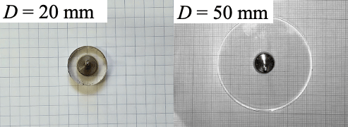
Figure 1
Photo of electrodes with flat plates.
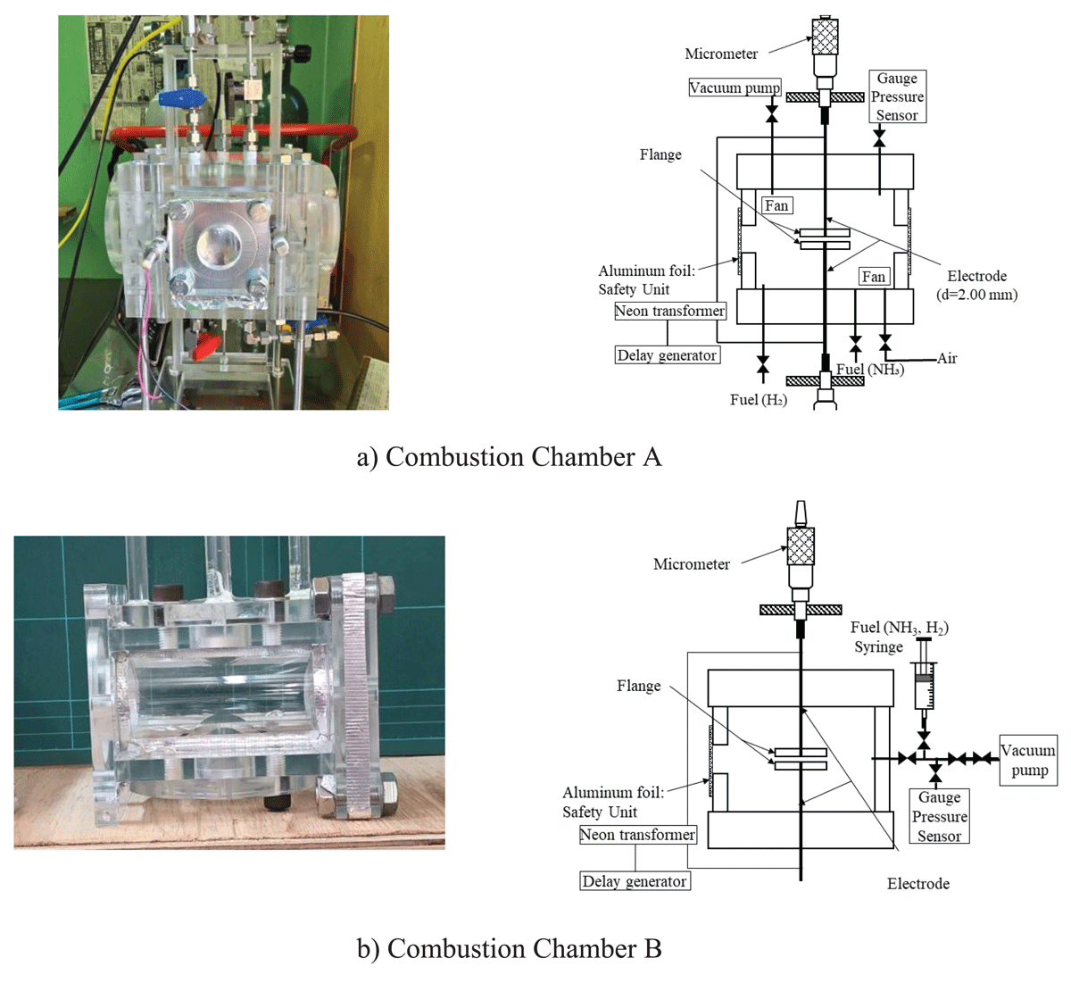
Figure 2
Schematics and photo of the experimental apparatuses.
Table 1
Experimental conditions of Combustion Chamber A.
| EQUIVALENCE RATIO, φ | ||
|---|---|---|
| 0.6 | 0.4 | 0.39, 0.41, 0.51, 0.61, 0.72, 0.82, 0.92, 1.03, 1.11, 1.21 |
| 0.7 | 0.3 | 0.45, 0.52, 0.62, 0.72, 0.82, 0.92, 1.03 |
| 0.8 | 0.2 | 0.57, 0.62, 0.72, 0.82, 0.92, 1.02 |
| 0.9 | 0.1 | 0.84, 0.92, 1.03 |
Table 2
Experimental conditions of Combustion Chamber B.
| EQUIVALENCE RATIO, φ | ELECTRODE GAP, d (mm) |
|---|---|
| 1.0 | 1.50, 2.00, 3.00, 4.00 |
| 0.9 | 1.50, 2.00, 3.00, 4.00 |
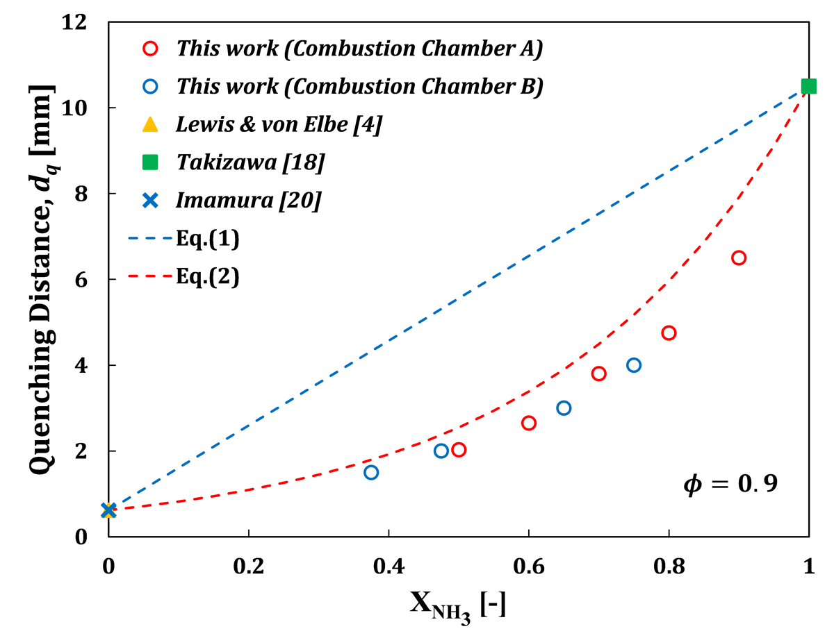
Figure 3
Dependence of dq on at φ = 0.9.
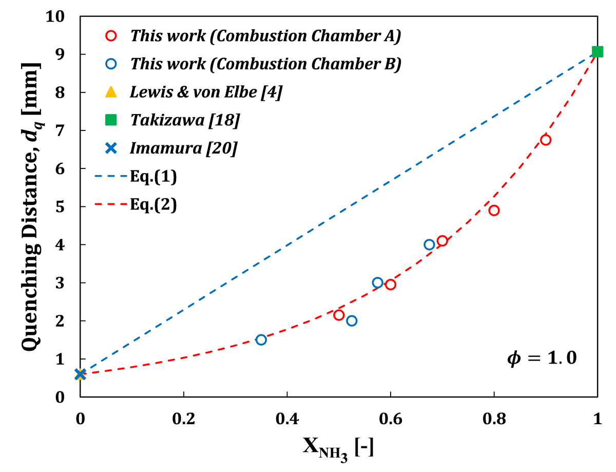
Figure 4
Dependence of dq on at φ = 1.0.
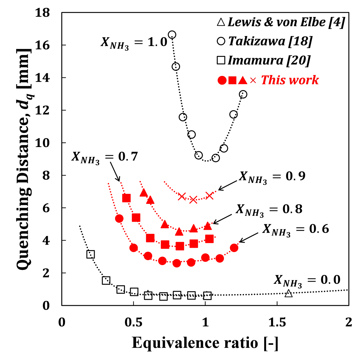
Figure 5
Relationship between dq and equivalence ratio.
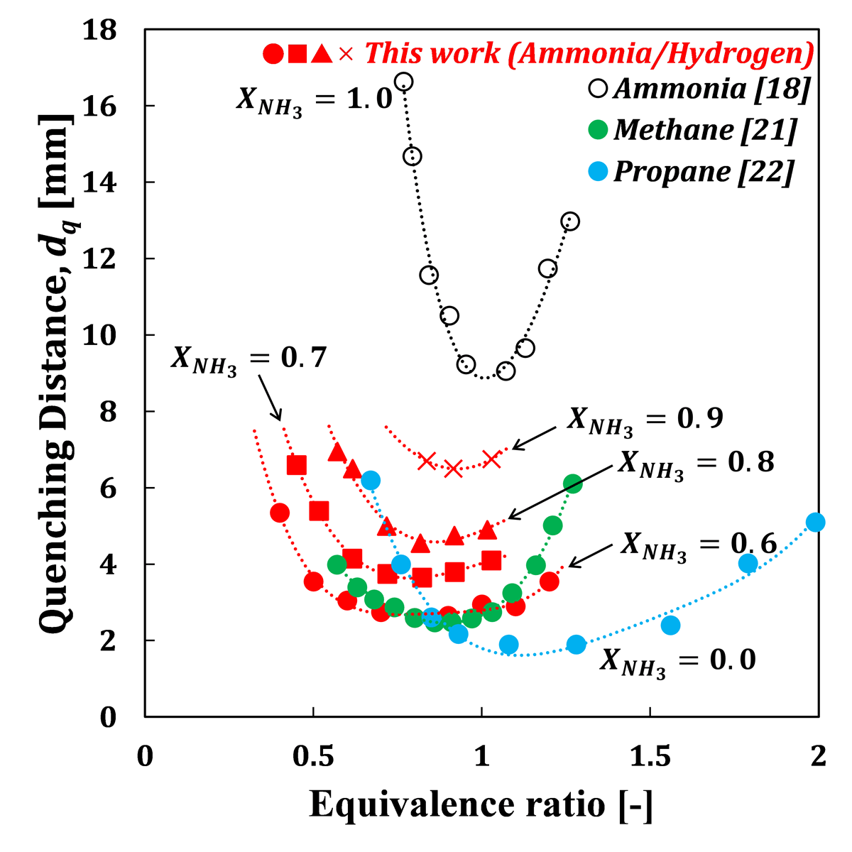
Figure 6
Comparison of this work with hydrocarbon fuel/air premixtures.
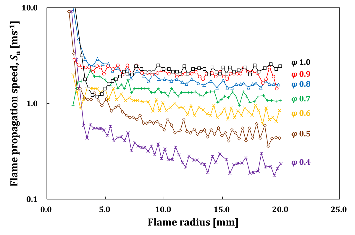
Figure 7
Relationship between the flame propagation speed and the flame kernel radius.
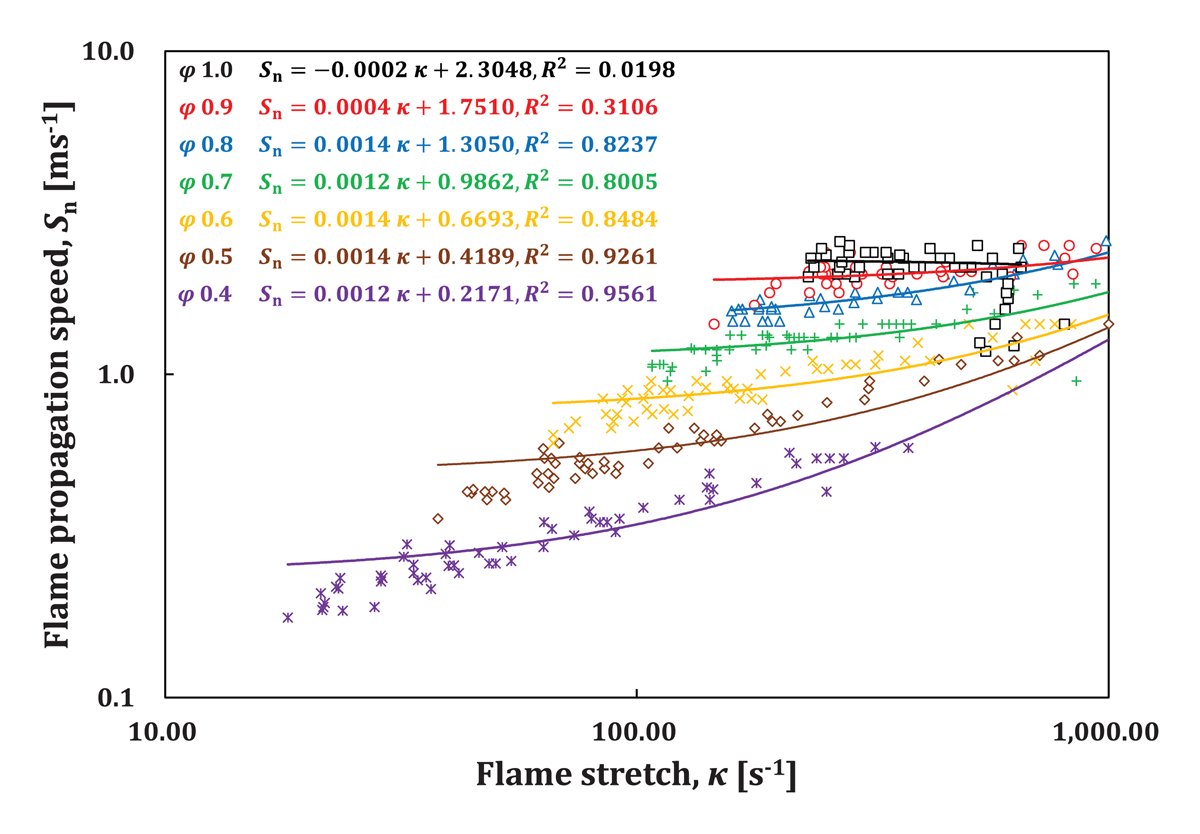
Figure 8
Relationship between the flame propagation speed and the flame stretch.
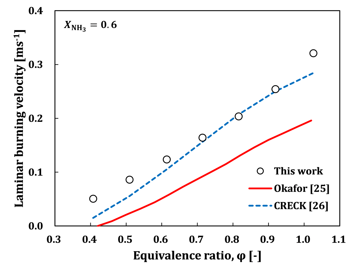
Figure 9
Relationship between laminar burning velocity and equivalence ratio.
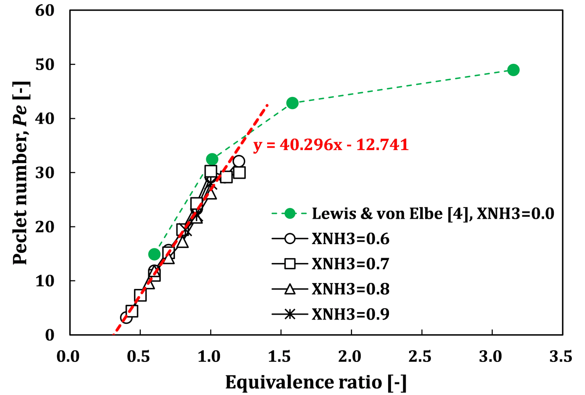
Figure 10
Relationship between Pe and equivalence ratio.
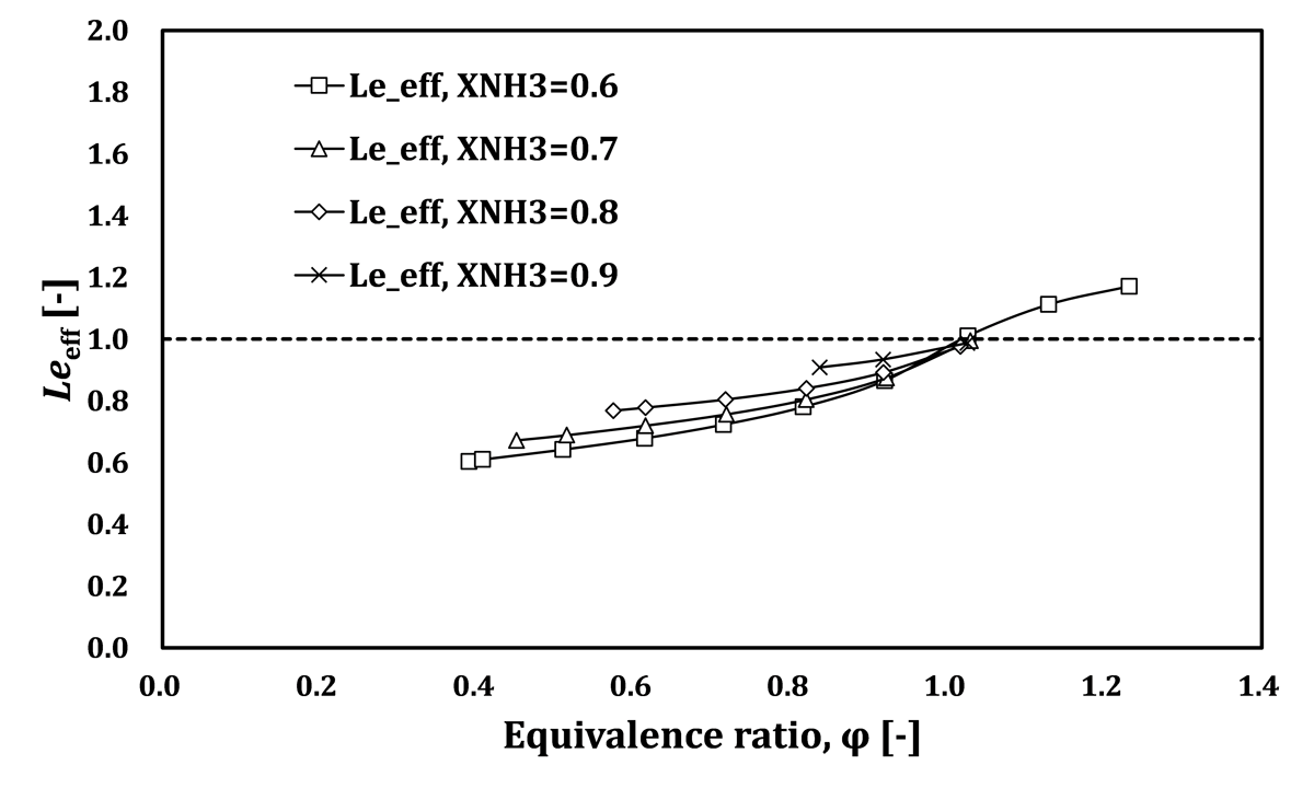
Figure 11
Equivalence-ratio dependence of effective Lewis number, Leeff.