
I. Introduction
Hydrogen has been identified as a key component of human society’s response to climate change, enabling decarbonisation of hard-to-abate industrial and transport sectors (IEA, 2023). This has translated into forecast global demand for green hydrogen (electrolytic hydrogen from renewable sources) of 0.5–2 TW by 2050 (McKinsey and Company, 2023) with capacity in Sweden forecast to rise to between 11 GW and 15 GW by 2045 (Energiforsk, 2024a; Swedish Energy Agency, 2021). Already, we see the world’s largest electrolytic hydrogen production facility (740 MW) under construction in northern Sweden (Montel Energy, 2024), and this is placing significant pressure on the electricity transmission grid to expand to facilitate this transition (SvK, 2024).
The first GW-scale hydrogen production facility in Sweden to begin construction is Stegra (formerly H2 Green Steel). Typical of co-located GW-scale industrial projects, the site at Boden has a strong grid connection, with an existing 400 kV substation that has three 400 kV incoming overhead line circuits as well as several 130 kV circuits. Stegra is mentioned solely as an illustrative example of electrolyser-substation co-location in northern Sweden. This paper does not constitute a site-specific safety risk assessment of Stegra’s facilities. The risks highlighted here are generic and may occur in any co-located industrial configuration where hydrogen and electrical infrastructure are in proximity.
Beside the existing plans at this example site, the hydrogen sector aspires for a hydrogen transmission network via hydrogen pipelines to secure supply for other industrial applications in northern Sweden (Wendt and Wallmark, 2022; Energiforsk, 2021; IEA, 2023; SvK, 2024; Hybrit, 2025). The adoption of green hydrogen as an energy carrier is likely to use electrolysis as its main production method and this necessitates many more grid-connection sites (electricity substations) to facilitate the interplay between electricity and hydrogen.
At all hydrogen electrolysis sites, co-location is inevitable at the grid-connection substation as hydrogen will be present once it is split at the cathode of the electrolyser itself. While the purpose of the hydrogen production may be to directly supply downstream processes, hydrogen gas will also be stored (in small volumes relative to the annual production volumes of the overall plant) and transported between the hydrogen production facility and the hydrogen demand use. (Stegra’s facility is an example of this, where sponge iron is made using hydrogen reduction, instead of a blast furnace, as part of the decarbonisation of the steel-making process.)
While physical separation between the electrolyser itself and the electrical substation infrastructure can be designed into the site layout, there is also hydrogen storage and pipelines to consider, along with electrical cabling and switchgear at a variety of voltages. This is typically 1 kV DC feeding the electrolyser stack, 33 kV AC feeding the power converter and (several) infeeds supplying the 33 kV busbar(s) via transformers to the 400 kV transmission grid. This is typical of the grid-connection arrangements that can be expected for GW-scale hydrogen production facilities.
The physical properties of hydrogen are well defined and studied (Lin et al., 2023), and several of them contribute to ignition risks. When released from a pressurised system, such as a tank or pipeline, hydrogen rises rapidly due to its low molecular weight. Its high diffusivity enables rapid mixing with air within seconds after the release. Two critical safety parameters are its wide flammability range (4–75% by volume in air) and its low minimum ignition energy of 0.017 mJ, both of which make hydrogen more prone to ignition than other gases. Sparks, hot surfaces (>585°C), electrostatic discharge, friction, or impact involving metal components can ignite hydrogen–air mixtures under the right conditions (e.g. a collision between aluminium and magnesium can generate small metallic particles with temperatures above 2000°C). Once ignition occurs, the high laminar burning speed increases the reactivity of hydrogen and raises the risk of a deflagration-to-detonation transition (DDT), generating a shockwave capable of damaging surrounding structures (Kotchourko and Jordan, 2025).
A typical means of mitigation is to provide a minimum distance between buildings and hydrogen infrastructure. However, these minimum distances are not well-defined, with highly conservative rules of thumb typically applied. There is recent progress on these challenges, with the H2SIPP-project coordinating research among universities, government, and industry (H2SIPP, 2025), and Energiforsk publishing an initial step toward guidelines for the co-location of buried hydrogen pipelines along transmission corridors, addressing associated hazards and concluding that more work was needed on risks before co-locating hydrogen pipelines and overhead electrical power circuits, with safety distances currently unknown (Energiforsk, 2024b). Vyazmina et al. (2025) provided a methodology for safety distances around hydrogen electrolyser units including leakage, jet flame and overpressure scenarios but did not provide safety distances themselves. Some specific cases from the literature attempt to provide safety distances, ranging from those in NFPA 55, around 4.6–7.6 m (NFPA, 2023), through 35 m for a hydrogen refuelling station (Barilo and Bingham, 2009) to 300 m for a GW-scale electrolyser (European Commission, 2024). There is high uncertainty and no consensus, other than on the value of site-specific detailed analysis.
The report by Energiforsk (2024) does not consider the co-location of electrical substations with electrolysers or hydrogen-carrying systems, which has been identified as a research gap. The present paper addresses this gap by identifying the main ignition sources derived from electrical assets, analysing typical accident scenarios, and assessing the risks associated with the proximity between electrical infrastructure and hydrogen production, transport and storage systems in GW-scale electrolysis facilities. In addition, mitigation strategies are presented from a qualitative approach, aiming to contribute to the development of future technical guidelines for the safe implementation of green hydrogen projects.
The risks highlighted in this paper are clear: released hydrogen gas can form flammable clouds that can extend up to 100 metres in seconds, bringing nearby substation infrastructure in the vicinity into reach under certain wind conditions (Edelia et al., 2018).
II. Method
This study analyses the hazards associated with hydrogen facilities co-located with electrical substations. An interdisciplinary technical review was conducted of the behaviour of hydrogen and its physical properties in combination with possible sources of ignition present in substations.
Based on this review, electrical assets capable of acting as ignition sources were identified and classified. Their spatial and temporal presence in typical 400 kV substations was assessed, considering their height above ground, their distribution within the site, and the duration for which they can generate ignition risk. This information was organised into a qualitative comparative table to prioritise risks according to their relevance.
In addition, the consequences of a hydrogen leak were analysed in scenarios where electrical equipment capable of acting as an ignition source is present. These events were organised in a logical sequence, from the initial leak to a possible ignition or explosion. This sequence is represented by an event tree, which allows us to visualise how an accident can evolve depending on the environmental conditions. Each relevant stage was analysed separately: the formation of a jet flame, the dispersion of the gas and possible delayed ignition (explosion). In each case, the factors that can influence its development were identified, such as pressure, wind, the geometry of the environment, or the degree of confinement.
Figures in Section VI were prepared as qualitative diagrams. Their purpose is to clearly show how different physical and design factors can affect the evolution of an accident. No numerical calculations were performed, and no probabilities were assigned, as the focus of the study is strictly qualitative.
Finally, potential mitigation measures were identified relating to site design, electrical equipment layout, and the evaluation of configurations that could reduce the risk of ignition, such as the use of gas-insulated switchgear (GIS) instead of air-insulated switchgear (AIS), where technically and environmentally justifiable.
III. Ignition sources
The typical electrical assets required to connect a GW-scale electrolyser to the 400 kV electrical grid are presented and potential sources of ignition arising from them are identified. The ignition sources are limited to the electrical assets themselves: human factors such as construction works, smoking and unauthorised site entry or vandalism are not considered.
A. Co-location of hydrogen and electrical infrastructure
This section explains why and how electrical assets—possible ignition sources—are co-located with hydrogen-containing infrastructure. It may not always be possible to maintain large separation distances between electrical infrastructure and hydrogen gas. Space-saving is often money-saving and so design compromises between cost and safety are important to understand.
There may be advantages to co-locating hydrogen pipelines and electrical infrastructure; for example, by laying hydrogen pipelines below an overhead line route, where the access has already been negotiated with landowners and trees are already felled along a sensible path. Energiforsk (2024b) considered this but did not consider substation trench routes, which may typically run around the internal perimeter of a substation and in a grid-like pattern connecting assets as well as crossing beneath rows of switchgear to hold electrical cables. There could be cost and space-saving advantages to using the same trenching for hydrogen pipelines as for electrical cables within a substation. These trenches are often partially, but not fully, covered, allowing airflow and drainage. Substation cable trenches often pass below or in proximity to energised electrical switchgear as can be seen in Figure 1, from a 400 kV substation in Germany with some of the trenching highlighted in green and exposed-to-air conductors highlighted in orange.
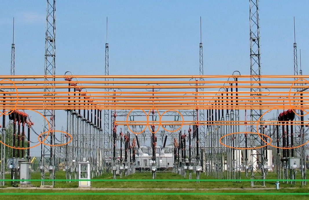
Figure 1
German outdoor 400 kV substation showing the location of cable trenching (green) beneath exposed 400 kV conducting assets (orange). Source: wdwd, CC BY 3.0 via Wikimedia Commons with orange and green indications added by the authors.
B. Transmission substation infrastructure
A GW-scale electrolyser will typically have its own dedicated grid-connection substation, and this will present a variety of ignition sources. This section identifies some hazards arising from electrical assets in a typical 400 kV electrolyser grid-connection substation that have ignition hazards associated with their operation.
This infrastructure is typically air-insulated (situated in the open air, commonly used outdoors) and hence exposed to the atmosphere, while GIS is chosen only for heavily space-constrained sites or those where pollution risks—such as coastal areas (salt residue) or special industrial sites (powder residues)—might be problematic. All 400 kV energised exposed conductors are elevated from the ground by at least the minimum vertical safety distance of 5.5 m (Albano et al., 2018).
The ignition hazards originating from the grid-connection substation for a GW-scale electrolyser are introduced in the following subsections and are compared in Table 1.
Table 1
Characteristics of transmission substation ignition sources.
| IGNITION SOURCE | HEIGHT(s) ABOVE GROUND (m) | TWO-DIMENSIONAL SPATIAL PREVALENCE (SURFACE AREA OF SUBSTATION OVER WHICH THE HAZARD MIGHT EXIST) | DURATION FOR WHICH THE IGNITION HAZARD IS PRESENT |
|---|---|---|---|
| 1) Disconnector switching | 5.5–12.5 | Single point sources, typically two per circuit or per primary plant item, three-phase so a six-circuit substation might have 36 single points. | Less than two instances per day, or less if used solely for maintenance outages, duration less than a second (IEC62271-102:2018). |
| 2) Insulator discharge | 5.5–12.5 | Single point sources on every primary plant item. 8–14 per circuit, three-phase, so a six-circuit substation might have 80 single points. | Varies with air quality, more research needed to quantify. |
| 3) Corona discharge | 5.5–12.5 | Every exposed conductor. Some areas have a mesh of conductors separated by minimum phase-to-phase safety distance of roughly 4 m. | Permanent for all energised exposed conductors. |
| 4) ROEP | Less than 2.5 | Every metallic structure could see this effect, a large set of single points throughout the substation. | Only from fault currents so rare and less than a second (IEC62271-102:2018). |
| 5) Spark gaps | 1.5–12.5 | Single point sources throughout the substation, on many supporting structures. | Only from fault currents so rare and less than a second (IEC62271-102:2018). |
| 6) Induced voltages | 0–12.5 | Vehicles or unearthed metallic structures, small surface area and likely away from conductors. | During site works or other human activities on site so rare but duration in order of hours is possible. |
1) Disconnector switching
There are several types of disconnector switch that are used in substations that employ various designs such as manual, mechanical and automatic rotating arms, pantograph disconnectors and disconnector circuit breakers. These are used along with circuit breakers and portable earthing apparatus to reconfigure the substation operationally and to disconnect and reconnect shunt and series elements as part of operational switching regimes or for routine maintenance. When de-energising equipment, temporary earthing is used to reduce the risks of induced voltages from energised equipment to de-energized equipment and to ensure that when two electrical contacts—for example, both poles of a disconnector switch or a busbar selector disconnector and the busbar itself—come together, there is minimum electrical potential between them and therefore arcing (which is an ignition source) is minimised. The operation of disconnector switching was designed without consideration of the proximity of co-located hydrogen gas and so existing substation switching operations may present an ignition source, even with minimised electric potentials from temporary earthing.
2) Insulator discharge
Tracking—small currents leaking across the insulator surface—could offer the potential for ignition as partial discharges occur across small sections of the insulator surface. The height above ground of the variety of insulator found in a substation is important as insulator bushings may be found from heights of two or three metres up to roughly twelve metres above ground. Moisture conditions in the air are important to this effect, which is greatest with high moisture content such as during rain or dense fog.
3) Corona discharge
Any non-smooth energised surface such as insulators or damaged conductors or busbars create ideal conditions for corona (Tabatabaei et al., 2022). Corona is a localised electrical discharge under high electric field stress. In cases where a conductor is pointed in shape, as opposed to a plate, then the electric field is concentrated to this point. If the breakdown strength of the air is lower than the locally generated field, then a corona current will be present. Corona discharge is characterised by the lack of a plasma channel and has a continuous current rather than a short, abrupt discharge. This situation is common with 400 kV overhead lines and busbars and can be heard as a crackle, most notably in damp air conditions.
For systems with nominal three phase voltage below 50 kV, the electric stress due to the energised conductors will typically be too small to ionise the air and so corona discharge will not occur (Tabatabaei et al., 2022). For a 400 kV substation, the ionisation of air—corona discharge—can be significant and will occur on all energised surfaces, regardless of smoothness, although pointed surfaces will see the greatest amount (Ahmuda, 2019). The plant objects that are susceptible to corona discharge will therefore include all air-insulated switchgear, busbars, overhead line gantries and overhead line circuits, both as they enter the substation and for the whole length of the circuit. This effect is therefore worthy of consideration for co-location of infrastructure within a single plant and when considering routing for hydrogen pipelines and storage and routing of electrical circuits.
4) Rise of earth potential (ROEP)
Another potential ignition source is earthing in and around the grid-connection substation. This is where a conducting surface is connected electrically to the general mass of earth to allow induced voltages to dissipate. Elevated potentials (rise of earth potential) above true earth potential can be found due to the impedance between the earthed structures in a substation and true earth, typically connected by an earth mat and electrodes. There is then a safety risk to humans who might touch the equipment in the substation, and a corresponding risk of spark creation.
5) Spark gaps
In northern Sweden, the 400 kV transmission comprises, almost exclusively, overhead lines. These lines are brought into substation compounds on structures such as those shown in Figure 2. Several standard designs are presented in a technical document published by SvK (2015) and all use a spark gap to electrically separate—under normal load conditions—the earthing structures of each loop of overhead line earthing conductor from its neighbouring sections and from the substation earth structure.
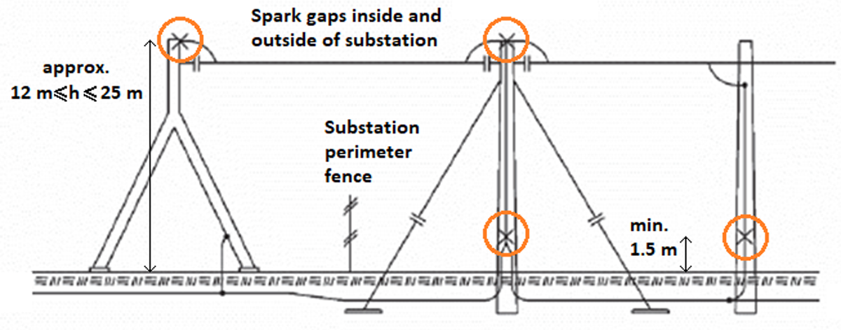
Figure 2
A gantry and tower earthing configuration, annotations added to SvK (2015), showing the locations of spark gaps in the earthing scheme of a 400 kV overhead line in proximity to a substation perimeter fence.
Spark gaps (circled in Figure 2) are used both within the substation perimeter compound and outside of it and may also be used on the down-dropper gantries and switchgear pedestals (structures that support the conductors as they enter the substation from the main overhead line towers). In the Swedish transmission network, these are preferred instead of directly earthing the tower structures and shield wires to reduce losses due to circulating currents along the typically long 400 kV transmission circuits. The spark gaps only activate during occasional overvoltages (such as during fault events).
6) Induced voltages
All metallic substation infrastructure will be bonded to the earth structure; however, non-infrastructure items such as vehicles, other plant or materials could be introduced to the substation environment for various durations. Human factors are outside of the scope of this research.
C. Summary of ignition hazards
Insights can be gained into ignition risk probabilities by considering the spatial and temporal presence of the ignition source: how much of the substation does it cover and is it always present? Table 1 summarises the spatial and temporal prevalence of each substation ignition source.
From the perspective of ignition hazard, the electrical phenomena considered in this research are ranked in approximate descending (1 to 5) order of concern:
Corona discharge. This is the most spatially prevalent phenomenon, forming (approximately) a two-dimensional mesh over the substation and along overhead line routes. It is continuously present to some degree on all energised conductors making it the most significant source identified.
Insulator discharge. Tracking along insulator/partial discharge on insulator creates small sparks. Contributing factors such as saltwater spray, air pollution, dust and melting snow and their prevalence and arc energies is identified as an area for further research to better understand the ignition hazard for hydrogen. Insulators are spatially prevalent in the substation and ordinarily continuously exposed to primary voltages at the conducting side so this could be a highly significant source.
Disconnector switching. Approximated spatially as single points within the substation where a disconnector makes or breaks connection with a busbar or other energised asset. Even though disconnectors do not make or break load (or fault) current, an ignition hazard exists at these points due to induced voltages from energised assets resulting in a small but possibly sufficient arc as the connection is made and/or broken. However, switching typically occurs twice per day for reactive switching schemes or a few times a year for maintenance outage operations, making this less of a concern.
Rise of earth potential and spark gaps. Any earthed structure can see elevated potential during fault conditions and spark gaps may flash over when subjected to fault currents. However, faults at transmission level, close to a substation, are rare and the spatial distribution of this effect is a series of single points. These phenomena do introduce the possibility of ignition sources located closer to ground height than the three effects above and so remain of interest but are expected to be less significant.
Induced voltages to external equipment and other human factors. Site works and construction activity could lead to metallic structures such as vehicles and building materials inducing voltages that might lead to an arc. This is unlikely with good construction design management and safe methods of working and its dependence on human initiation places it out of scope of this research. Other human-initiated ignition sources such as smoking materials or portable electrical apparatus also pose a hazard and are also out of scope of this research.
Corona discharge and insulator discharge are the two main mechanisms of concern highlighted by this study.
IV. Typical accident scenarios
Having analysed the ignition sources present in environments where hydrogen systems are integrated with electrical infrastructure, it becomes necessary to investigate how a large hydrogen gas release might result in various accident scenarios. This analysis uses the event tree methodology, which can be used to divide accidents into partial events.
Figure 3 presents a schematic event tree that shows the most probable sequences of events initiated by a hydrogen leak in facilities where this gas is handled under pressure. Less probable sequences are excluded for the sake of brevity.
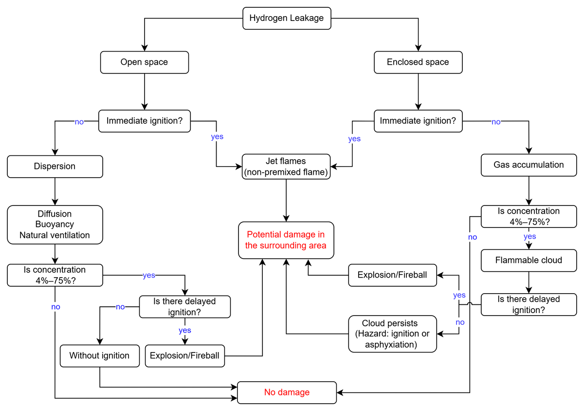
Figure 3
Event tree illustrating the hazards and consequences arising from hydrogen leakage (Molkov, 2012; El-Harbawi, 2022).
As seen in Figure 3 this tool, described in the Center for Chemical Process Safety’s Guidelines (CCPS, 2008), allows for the hazards involved to be identified and their influence on the evolution of each scenario to be analysed, from the dispersion of hydrogen and the formation of flammable mixtures to its ignition and the different modes of combustion (Sánchez and Williams, 2014; Yang et al., 2021). The structure of the event tree distinguishes between two environmental conditions following a leak: open and enclosed spaces. In open spaces, such as areas surrounding substations with overhead lines and exposed electrical equipment, immediate ignition can occur if the released hydrogen encounters ignition sources like hot surfaces. This leads to the formation of jet flame, characterised by non-premixed combustion, which can result in significant thermal effects on nearby structures. If no immediate ignition occurs, hydrogen disperses due to buoyancy and natural ventilation, but may also lead to fireball, flash fires and deflagrations (Lin et al., 2023) in electrically active environments. In enclosed or partially confined environments, such as technical compartments or cable trenches within substations, hydrogen may accumulate before ignition occurs. If flammable concentrations are reached, a delayed ignition in these settings can result in deflagrations or even detonations, depending on the level of confinement and reactivity of the mixture (Xing et al., 2022).
Although the partial events shown in Figure 3 can occur in different industrial hydrogen production configurations, an accurate risk assessment requires adapting the analysis to the conditions of the site. Factors such as the physical layout of the equipment, operating conditions and proximity to ignition sources significantly modify the probability of occurrence and the severity of the consequences (Crowl and Louvar, 2001; El-Harbawi, 2022). In this context, the proximity between hydrogen systems and electrical infrastructure is particularly critical, where substations with overhead power lines may be located close to hydrogen production and storage units. This configuration is taken as a reference to examine in detail how certain partial events in the tree can evolve under conditions associated with co-location scenarios. Each partial event is analysed in detail in the following subsections.
A. Initiating event
Although accidents such as external fire exposure to hydrogen storages or pipelines are possible, the main immediate threat is a leakage of hydrogen into the surroundings. As such, this is defined as the primary initiating event: hydrogen leakage into the surroundings from a hydrogen storage unit (tank, cavern or pipe) within or close to the electrolysis plant. As shown in Figure 3, this event serves as the starting point in the sequence of possible outcomes. Once a leak occurs, two key aspects must be considered: (1) whether ignition happens immediately or is delayed, and (2) whether the released hydrogen can accumulate and form a flammable mixture. These factors determine the subsequent development of the scenario and the severity of its consequences.
B. Direct ignition and jet flames
When hydrogen leaks from a pressurised system, direct ignition can occur if the released gas encounters an ignition source located near the point of discharge. This ignition mode is particularly relevant in environments such as electrical substations, where electric arcs or equipment capable of generating electrical discharges can exceed the minimum ignition energy of hydrogen, which is significantly lower than that of most conventional flammable gases. In the event of direct ignition, a jet diffusion flame is expected for as long as there is a leak providing fuel. The extent and behaviour of this flame depend on factors such as system pressure and leak orifice geometry. Under high-pressure conditions and with significant volumes of gas, sustained flames with the ability to reach considerable distances can be generated (Abohamzeh et al., 2021).
In addition to storage pressure, ambient conditions significantly affect the behaviour of the jet flame and the intensity of the thermal radiation it emits. In open environments, wind can enhance turbulent mixing between the released hydrogen and the surrounding air, which increases flame length and intensifies the combustion front (Liu et al., 2021). Another phenomenon that influences the trajectory of the jet flame is the Coandă effect, whereby the hydrogen jet tends to adhere to nearby solid surfaces instead of rising freely due to buoyancy. When ignition occurs under these conditions, the flame can follow the geometry of these surfaces, increasing thermal contact time and the likelihood of localised damage. This behaviour is particularly critical in installations co-located with electrical substations, where metallic structures and energised components can not only act as ignition sources but can also absorb or reflect part of the thermal radiation incident on their surfaces. Painted or oxidised surfaces have high emissivity and low reflectivity, whereas exposed metallic surfaces have low emissivity and high reflectivity. The sequence of events described corresponds to one of the pathways illustrated in the event tree shown in Figure 4, specifically associated with direct ignition scenarios resulting from high-pressure hydrogen releases, where these effects eventually lead to an increased flame length.
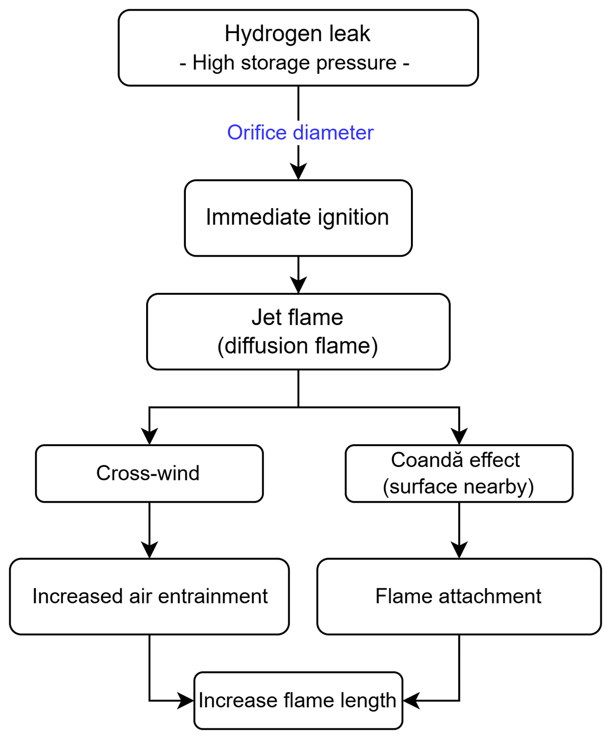
Figure 4
Jet flame development from high-pressure hydrogen leakage, influenced by wind and nearby surfaces.
In confined spaces within the substation, such as areas surrounded by walls or equipment enclosures, flame behaviour changes due to restricted airflow and reduced heat dissipation. Experiments with hydrogen jet fires in semi-confined configurations have shown that, when the flame impinges on a surface, limited ventilation can cause about 80% of the panel area to reach temperatures above 400°C, compared with about 51% under open conditions (Meraner et al., 2025). Although these experiments were not conducted in a substation, the results suggest that a similar situation in a confined area could lead to higher thermal exposure and a greater risk of damage to the electrical infrastructure.
C. Dispersion and delayed ignition
Even if hydrogen storage units are placed separately in the open, with no possibility of accumulation or ignition after a leak, the possibility remains for spread to a nearby substation in the vicinity associated with the overall site to occur, where a flammable mixture could meet a mesh of ignition sources at varying heights above and around the substation. A very different set of outcomes is possible if no direct ignition occurs. For example, the results of a numerical study of hydrogen dispersion implied that the flammable cloud could extend up to 100 metres and beyond in seconds after the release under the influence of wind (Edelia et al., 2018). Wind is just one factor that can affect the outcome. Additional factors that affect hydrogen dispersion in air are summarised in Figure 5.
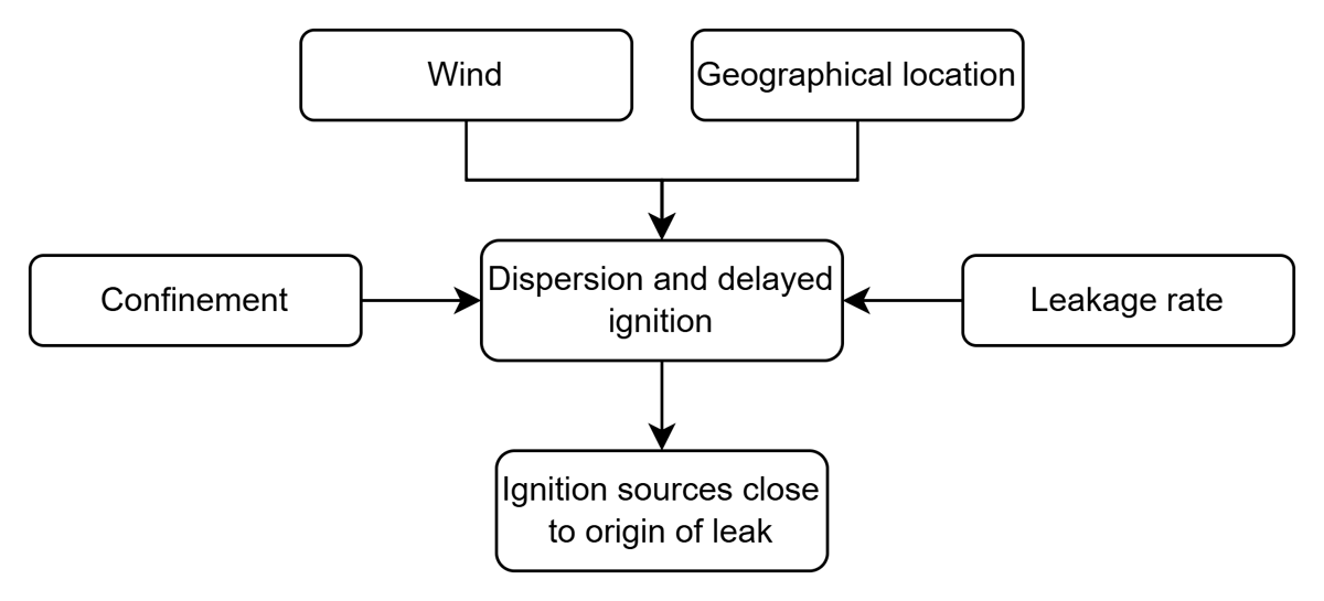
Figure 5
Identified factors that affect the outcome of the partial event related to dispersion and delayed ignition.
All contributing factors now point to ‘Dispersion and delayed ignition’. The arrow to ignition sources is included to indicate that ignition may occur if an external source is present after dispersion, rather than implying that ignition has already taken place.
A crucial property of hydrogen is how quickly it disperses into the air and rises through it compared to other gases. This physical aspect implies that hydrogen–air mixtures will quickly extend outside the area of the immediate leak. The potential for a large hydrogen–air cloud is possible, but the hydrogen will quickly be diluted in the air. This means that the rate of release from the leak and the rate of dilution will decide the size of the cloud, i.e. hydrogen-air mixture. Thus, a high-pressure vessel has a higher potential for larger flammable cloud formation.
The hydrogen–air cloud is not necessarily flammable in all parts, but it offers a higher possibility of ignition as the flammable range is quite wide as opposed to that of hydrocarbon fuels. The possibility of accumulation is another important factor, which is defined by the extent of confinement, ranging from full enclosures (buildings) or part enclosures (canopies), cable trenching of varying degrees of containment, to assets placed in the open air (freely placed storage units). A higher level of accumulation and lower level of dilution in the air can be expected with a higher degree of confinement. Conversely, where free dispersion into the open atmosphere is possible, the level of dilution is high, and accumulation is not expected.
Furthermore, the broad flammability range of hydrogen–air mixtures enables rich flammable mixtures which, in combination with hydrogen’s lower ignition energy, suggest that ignition is more probable in the early onset of a leak. Thus, large cloud formation might be less likely for hydrogen as opposed to other energy carriers.
Wind and environmental configuration are additional factors that also significantly influence hydrogen gas dilution in air, as illustrated in Figure 5. High wind speeds will be more prone to diluting the mixtures due to large air entrainment into the cloud, but lower wind speeds increase the likelihood that a flammable cloud is pushed along with the wind direction. The additional air entrainment dilutes the cloud but also moves it in the wind’s direction: increasing dilution will eventually lead to a non-flammable mixture, but at the same time will increase the spread of the cloud. If a hydrogen production facility is placed at a higher altitude, then the flammable mixture would be inclined to move above the facility due to its high buoyancy, irrespective of the wind direction or speed, and as such, no ignition sources within an electrical substation could be reached.
The leak, and succeeding cloud, need to be in an environment where there is an ignition source for ignition to be possible. In enclosures within a hydrogen production unit, a flammable mixture to ignition routes is possible: 1. encounter a solid hot surface (>585°C), or 2) encounter a spark-inducing element with the potential to generate a spark ignition, as seen in Figure 6. In this case, the hot surface ignition is improbable, as neither the production process itself nor the substation is likely to have surface temperatures of more than 585°C. In a case where a leak occurs from a hydrogen storage unit in the open, and the flammable cloud does not interact with solids or other potential ignition sources, then the formation, spread and ignition of a larger flammable cloud becomes more probable. The absence of ignition sources allows formation of a larger flammable cloud as opposed to when ignition sources are available in a more encroached area. Once again, the physical properties of hydrogen (wide flammability and low ignition energy primarily) imply that although delayed ignition is possible, the duration between release and ignition will be limited if an ignition source is present in the vicinity of the release.

Figure 6
Identified features of the partial event related to delayed ignition of a flammable cloud.
The impracticalities of removing all ignition sources for large distances around all hydrogen facilities are discussed in Section IV A. If ignition sources at the substation and/or the possibility of accumulation could be minimised, then hydrogen would be expected to quickly rise above the ground and disperse into non-flammable mixtures. However, one relevant question is, whether this can be quantified for deciding, for example, zones of minimal probability for ignition.
All these factors related to cloud formation are too complicated for qualitative analysis, and therefore, quantitative analysis with numerical calculation models is recommended as an aid to draw conclusions from a more detailed understanding of cloud formation. Likewise, the ignition probability with various mitigation measures cannot be qualitatively assessed and therefore quantification is required to understand the effect of the mitigation measures.
D. Explosion events
In the case where a flammable cloud reaches ignition sources in a substation and an ignition of the mixture occurs, there are several possible combustion modes for the pre-mixed cloud, as summarised in Figure 7 (in which yellow indicates a low consequence, orange mid-range consequences and red high consequences). Combustion modes include stationary non-accelerating combustion, e.g. jet flames, but also more transient accelerated combustion such as deflagration or detonation. Although hydrogen and air is a reactive mixture, its hazard heavily depends on the conditions at the position of the ignition and its immediate surroundings. A close-to-stoichiometric homogeneous mixture will generate high-speed deflagrations, which can generate significant pressure gradients, resulting in loss of life and property. However, it is important to relate this to the scenario at hand. Given that a release source of pure hydrogen gas is available, the flammability changes as hydrogen concentration is diluted when air is entrained in the cloud. This implies that the edge of the cloud will be increasingly diluted as the cloud expands. Thus, the mixture that reaches an ignition source further away will be closer to the lower flammability limit, i.e. a low hydrogen–air ratio. A possible scenario depending on the location of the ignition source is that the flame propagation speed could therefore start slowly and move against the origin of the leak and then potentially accelerate, building up pressure against the origin of the continuous release as the mixture becomes richer and closer to stoichiometric conditions as the flame front propagates. However, as the mixture becomes richer closer to the release the flame propagation speed will slow again and pressure build up will decrease given that DDT does not occur. This process is therefore highly dynamic and dependent on the concentration and heterogeneity of the cloud.
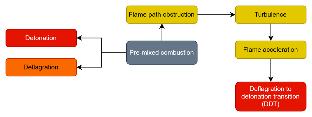
Figure 7
Aspects affecting pre-mixed combustion. Danger potential from yellow to red, where yellow indicates low consequences, orange midrange consequences and red high consequences.
Since ignition will occur at the edge of the cloud, the potential acceleration will generate pressure build-up as the flame returns to the hydrogen facility and affect the hydrogen facility rather than the electrical substation. This scenario with a non-confined path in the cloud for flame propagation does not imply detonation, but if congestion, e.g. trees or auxiliary equipment, are in the path of the flame propagation, then within-cloud detonation is more probable due to the acceleration-increasing effect of congestion in the flame-propagation path, as seen in the Buncefield accident (Oran, Chamberlain and Pekalski, 2020). The increased flame acceleration would make DDT more probable, leading to much more severe consequences as the subsequent detonation produces significantly higher pressures than a deflagration, which would imply much longer safety distances.
E. Analysis of accident scenarios
Each stage from initial leakage through to final consequence and potential loss of life and property involves set of possibilities with many variations. While all partial events have a probability, it is hard to quantify these as accident data is scarce, but it is possible to make estimations as to which events are more probable than others, using a physical basis for assessment. This increases understanding of which scenarios are more likely to have the most severe consequences, leading to a better general understanding of the risk at a particular facility.
For example, consider a storage system associated with an electrolyser operating at 20–40 bar, where hydrogen leaks from a pipe through a hole with a diameter between 5 and 50 mm (Lin et al., 2023; Molkov, 2012). In open environments, hydrogen dispersion depends mainly on wind speed, typically in the range of 1–6 m s–¹ (Yang et al., 2021), while in enclosed or partially confined spaces dispersion depends mainly on the ventilation conditions of the enclosure, which determine air exchange and potential hydrogen accumulation. Under standard ambient conditions of 293 K and 1 atm, these parameters allow estimation of the region where the hydrogen concentration exceeds the lower flammability limit (4% by volume in air). In the presence of high-voltage electrical infrastructure, such as those found in 400 kV substations, corona discharges in air associated with voltages on the order of 5–30 kV may occur (Tabatabaei et al., 2022; Ahmuda, 2019). As the minimum ignition energy of hydrogen is approximately 0.017 mJ, these electrical phenomena may act as potential ignition sources (Yang et al., 2021; Sánchez & Williams, 2014). Using these parameters, the jet flame length, thermal radiation distances, and overpressure levels could be estimated in more detail for the specific site at hand, enabling a more detailed assessment of potential damage to electrical equipment, cables, and nearby infrastructure, as well as an estimation of safety distances between hydrogen systems and electrical assets (Edelia et al., 2018; NFPA, 2023).
The likelihood of each partial event can be estimated, but some event stages are more difficult to quantify than others. A detailed analysis is then required. It is through detailed analysis accompanied by consequence modelling that more accurate indications of the relative probability of each subsequent stage can be acquired. Various methods are available to quantify the cumulative probabilities and the relative consequences, but the common term used is quantitative risk analysis or QRA (Kotchourko and Jordan, 2025). In general, the greater the number of independent steps that are introduced, the less likely the chain of events is to occur. For example, in the event of leakage from a storage unit (storage or pipeline), for scenarios where a flammable cloud is assumed to have formed, then co-location (e.g. release beneath a mesh of energised conductors) can lead us to skip the question of safety distance probability and take us directly to ignition. Where there is no co-location, we have the additional probability step of the cloud reaching an ignition source outside of the facility as opposed to the first case, in which we directly get ignition within the facility. Having more partial events incorporated in the event tree can thereby provide a more detailed understanding of the scenarios.
To estimate the consequences of the chain of events where transition occurs from leakage to cloud formation and spread, a suitable model of the immediate physical environment (hydrogen pipeline and surrounding structures, obstacles, wind velocity) is needed to enable consequence analysis of each partial event, separate or combined. It is deemed necessary to use numerical simulations, such as computational fluid dynamics (CFD), to capture the complexity of the accident conditions described in the example with the storage above.
Furthermore, the probabilities for each of these partial events need to be specific to the site and situation to get a representative value of the probability. These tasks require complex and time-consuming modelling and analysis. Nonetheless, it is an essential stage in estimating risks and finding adequate measures to have an acceptable residual risk and thereby be able to confidently define a hydrogen site as safe.
V. Ignition mitigation measures
Electrical substations have been demonstrated to contain large amounts of equipment that can generate sparks, creating an environment where a hydrogen leak could trigger catastrophic events if not properly managed. The location and layout of such substations and their equipment with respect to the surrounding environment are crucial factors that affect the outcome in a leak scenario, which could be non-consequential or catastrophic depending on local conditions.
A. Mitigation by substation layout
There are two main options for the location of hydrogen electricity-grid-connection infrastructure: indoors and outdoors. When hydrogen-containing infrastructure such as pipelines and storage are outdoors then they can more easily be physically separated from electrical infrastructure. Physical separation is one mitigation measure, but it is not zero-risk since total separation is difficult if not impossible at the grid-connection substation due to the need to power the electrolyser units themselves. Attempting to increase separation as far as possible comes with cost and practicality constraints. Protection from jet flames could include enhanced cooling systems for exposed hydrogen installations (e.g., storage vessels) and nearby electrical equipment, implementing barriers or shields to reduce radiative heat transfer, and ensuring that critical components are adequately insulated from potential flame exposure (Lee, 2008; Molkov, 2012). Such barriers are in place today between electrical transformers within a substation, where their purpose is to prevent fire from one transformer causing overheating of the internal oil in an adjacent transformer, as well as offering explosion protection.
There is also the possibility that hydrogen gas could escape within or towards an indoor environment. Indoor environments that contain hydrogen gas inevitably include the electrolyser stacks themselves. It is usually possible to locate this building physically far from the electrical substation; however, there are cases where this might not be desirable or possible. If trenching is to be used to pass hydrogen pipelines through a substation, then perimeter trenching rather than utilizing trenches running through the substation might offer a better way to separate gas from ignition sources in the event of leakage. The same principle applies to above-ground hydrogen pipe routes. Partial confinement also exists, where, for example, snow covers or non-airtight containment in the trenches enables mixtures of hydrogen and air as well as movement of this flammable mixture to other areas of the site. Understanding this scenario requires detailed site-specific consequence modelling.
In the context of explosions, mitigation techniques such as ventilation and blast vents play a critical role in enclosures. The rapid dispersion of hydrogen towards high areas and ceilings requires emergency ventilation systems to be designed to effectively eliminate the gas before it accumulates in flammable concentrations (Kotchourko and Jordan, 2025). Blast vents are used to control pressure build-up during an explosion, which is particularly important in congested environments, where flame front acceleration can occur. In such scenarios, the design and placement of vents are crucial. For example, studies have shown that the venting process can accelerate the flame front toward the vent, though it has minimal effect on the flame behaviour on the opposite side, indicating the need for strategic vent placement to minimise risk (El-Harbawi, 2022). Likewise, congestion can significantly affect the pressure build-up of the explosion and therefore minimising congestion and enclosing features are equally important in outdoor environments. Should this not be possible, it is crucial to investigate blast resistant structures such as blast walls.
B. Mitigation by ignition source
There are also design approaches that can reduce ignition risk by tackling the ignition source. Corona discharge can be reduced on overhead line circuits by employing multiple conductor bundles for each phase, by selecting a conductor with larger radius, by selecting conductor types that are smoother, employing corona rings to increase the linearity of the electric field distribution, and ensuring proper maintenance (Ahmuda, 2019; Tabatabaei et al., 2022). However, the busbars themselves, despite being relatively smooth surfaced, will still not be free from corona discharge. Additionally, there are other plant items that are found connected to the conductors that are also energised that are not smooth and these offer the edges at which electric field intensity will be highest. Examples include bundle spacers on overhead line bundles, busbar clamps and the conducting support structures with which busbars connect to plant items, such as voltage or current transformers or circuit breakers.
An important consideration when designing for fire safety of co-located hydrogen-containing infrastructure and electrical substation assets is that the high spark possibility might be considered as a weak form of mitigation in itself as it does not allow for long-delayed ignition and thereby reduces the risk of large explosions. Nevertheless, it should be seen as beneficial rather than a design strategy. Barrier design focus could thereby be placed on jet flame mitigation rather than on explosion barriers. Detailed context-specific analysis at each location is required to inform design trade-offs of this sort.
Besides the consideration of energised electrical assets as ignition sources, it is possible that human factors could present hazards. There is an ever-present risk from human action such as smoking, use of portable electrical equipment, vehicles and temporary activities such as construction leading to additional spark risk and induced voltages if conducting materials are on or close to the site without appropriate earthing. The mitigation of these risks is behavioural and part of an on-site safety culture and is not within scope of this research.
C. Mitigation by gas-insulation of switchgear and conductors
When looking at mitigation measures for corona and insulator discharge—the two most significant ignition sources identified—the obvious contender is gas-insulated switchgear. Standard and compact vertical air-insulated switchgear (AIS) substation designs reduce the substation footprint (Albano et al., 2018) but are not without their concerns from the ignition risk perspective, as the creation of indoor AIS environments creates the possibility for the explosion of a flammable cloud.
The costs—monetary and environmental—of GIS switchgear should be considered when designing grid-connection substations for hydrogen production or for any other co-location case. The gas insulating medium typically used is Sulphur Hexafluoride (SF6), with National Grid Electricity Transmission (NGET) in the UK citing a lack of available alternatives (NGET, 2021), despite the well-understood greenhouse gas effects of leakages (IPCC, 2013) and the high leakage rate on the NGET network (OFGEM, 2022). In addition, GIS has a significantly higher cost, is harder to maintain and repair, and is considered by the NGET to be more difficult to operate (NGET, 2021). As such, GIS is typically not preferred but is still deployed in certain situations, such as where space constraints necessitate it. It may be that grid-connection substations for hydrogen production offer a justifiable use case for gas insulation in substations. Furthermore, technology has advanced significantly and there is promise for less-environmentally damaging insulating media, with alternative gas mixtures to SF6 in development and some, such as GE Vernova’s G3, being close to commercial availability for most (but not yet all) 400 kV GIS SF6-free assets (GE Vernova, 2024).
The main benefit of GIS over AIS switchgear from an ignition risk perspective can be seen in Figure 8. Comparing Figure 8 (GIS) to Figure 1 (AIS), there are fewer exposed conducting surfaces when GIS switchgear is used. The physical tanks that contain the insulating gas remove the exposed conducting surfaces, thereby removing the possibility of hydrogen gas mixture encountering the exposed conductor and its associated ignition hazard. When considering the presence of corona discharge or partial discharges along insulators (tracking) as ignition sources, the substation shown in Figure 1 could be described as a tight mesh of ignition sources from heights of roughly 1.5 m above ground to the upper reaches of the substation. Typical heights of the exposed conductors and insulators are between 5.5 m and 12 m. Gas-insulated switchgear removes most of these exposed conductors from the physical substation layout. The remaining exposed insulator surfaces and conductors from GIS installations are highlighted in in Figure 8, where orange shows insulator bushings offering possible tracking and yellow shows downdropper conductors offering possible corona effects.
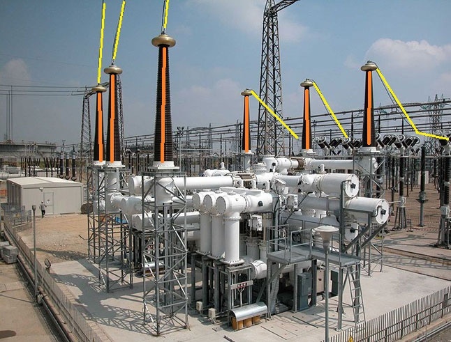
Figure 8
400 kV gas-insulated switchgear (foreground) with six (vertical) GIS–AIS transition bays. Ignition sources from tracking (orange) and corona discharge (yellow) are highlighted. Notable is the lack of sources at lower levels. Source Dingy, CC BY 4.0 via Wikimedia Commons.
VI. Conclusion
Ignition risk is always present in and around a transmission substation. The substation environment comprises ignition sources at heights ranging from ground level up to 12 m above ground or higher. With many potential ignition sources spread across the substation layout, the substation environment resembles a three-dimensional mesh of potential ignition sources, some of which may be regularly creating sparks of sufficient energy to cause ignition of leaked hydrogen. It is therefore a defensible starting assumption that all hydrogen releases that could meet electrical substation infrastructure will be ignited.
Co-locating electrical and hydrogen-containing infrastructure has cost-saving benefits, can simplify design and can be desirable in space-constrained sites. However, the lack of practical experience and theoretical research into the risks of co-location typically leads to a decision to avoid co-location as much as possible. Where co-location is required, the use of gas-insulated switchgear—ideally non-SF6—should be considered as it has the potential to significantly reduce the number of exposed conductors and insulators.
Indoor environments and varying degrees of containment from trenching provide the possibility of accumulation and explosion. It is therefore important to implement proper detection and ventilation measures to prevent hydrogen build-up and to minimise conditions that could lead to ignition, thus ensuring the integrity and operational safety of the electrical substation.
Outdoor environments have many varying conditions, e.g. wind, which affect the dispersion and hydrogen–air cloud formation for a leak that is not ignited instantaneously. The cloud can have a range of hydrogen concentrations and shapes. If a flammable cloud ignites at a distance from the source of release, the flame may propagate back to the source of release, causing pressure build-up towards the hydrogen infrastructure rather than the substation. Although it is hard to mitigate cloud formation and spread without implementing confinement, it is possible to use blast walls as a mitigation measure to reduce the damage from a gas explosion.
In cases where a leak is ignited instantaneously, the possibility of impingement and radiation from jet flames to surrounding structures or objects exists. The properties of the leak itself are important here: pressure and stored volume largely determine the size of the jet flame. Mitigation measures such as barriers can offer some ability to limit the consequences of an event and should, if possible, be combined with blast walls.
It is evident from this non-exhaustive qualitative analysis of ignition hazards and possible accident scenarios in relation to co-location of hydrogen infrastructure and electrical infrastructure that a range of factors can affect dispersion, jet flames or hydrogen gas explosions. However, most of them can be analysed using more advanced tools, e.g. computational fluid dynamics (CFD), to understand the consequences. A range of ignition sources and their typical locations have been identified, which can provide valuable information for consequence analysis and, ultimately, risk analysis. This demonstrates the importance of interdisciplinary work in the design of safe hydrogen infrastructure close to electrical substations.
Another outcome is that as there are so many variables affecting the outcome of jet flames or explosions, it is the authors’ opinion that a safety distance, e.g. 60 m, will not be definitively conservative. Any attempt to construct general guidelines of safety distances must weigh in many factors, such as pressure, storage volume and congestion confinement. Comprehensive consequence analysis and quantitative risk analysis will be the favourable option to ensure safety while not being overconservative in design, enabling the emergence of safe hydrogen infrastructure.
VII. Recommendations for further research
The obvious and still-open research question is ‘what is a suitable minimum physical distance between hydrogen and electrical infrastructure?’ A set of conservative rules of thumb for separation, as exists for natural gas, requires a deep body of research including large and detailed records of historical accidents and experience, neither of which are available to a sufficient extent.
The representative parameters discussed in the accident scenario analysis illustrate the type of conditions that would need to be evaluated in future quantitative studies. Determining suitable separation distances will require systematic modelling of such scenarios and validation through numerical and experimental studies.
To move towards an understanding of recommended separation distances requires to first understand the accident scenarios for every probable installation where hydrogen gas and electrical infrastructure could be within proximity and then perform a risk analysis against consistent and agreed criteria to ascertain the distance at which the risk is below a defined threshold. This task is beyond the scope of this paper but constitutes important future research that will require collaboration between utilities, project developers, equipment manufacturers and plant and system design engineers. International coordination and standardisation are an important future task to enable compatible safe design.
The areas in which research is most acutely needed include:
Electrical substation assets, including ignition source characteristics and withstand capabilities.
Detailed analysis of electric field intensity and spark generation along insulating surfaces (tracking) and from conducting surfaces (corona discharge) to better understand the likelihood of sufficient spark conditions to cause ignition.
Electrical asset withstand capabilities from typical hydrogen jet flame radiant heat flux and shockwaves.
Electrical asset withstand capabilities from explosion of hydrogen-based flammable cloud and associated dynamic loading.
Accident scenarios, including probabilities and quantitative analysis.
Leakage mechanisms and probabilities.
Probability of ignition of electrical components.
Full event tree analysis incorporating quantitative probabilities for each partial event for typical site layouts using, for example, Monte Carlo models.
Mitigation design, both as add-ons such as blast walls and as safe-by-design site-specific layouts.
Large-scale numerical dispersion simulations of typical site layouts with a range of parametric studies including aspects such as wind speed and direction at various pressures and quantities of hydrogen to understand cloud formation.
Numerical studies of hydrogen–air cloud explosions in relation to electrical components in electrical substations.
Large-scale numerical simulations of typical site layouts with jet flames incorporating parametric studies of various release conditions including aspects such as pressure and storage volumes.
Large-scale experiments to validate numerical simulations of gas explosions, dispersion and jet flames.