
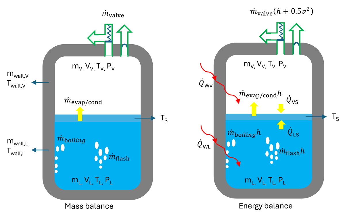
Figure 1
LH2 tank non-equilibrium model.
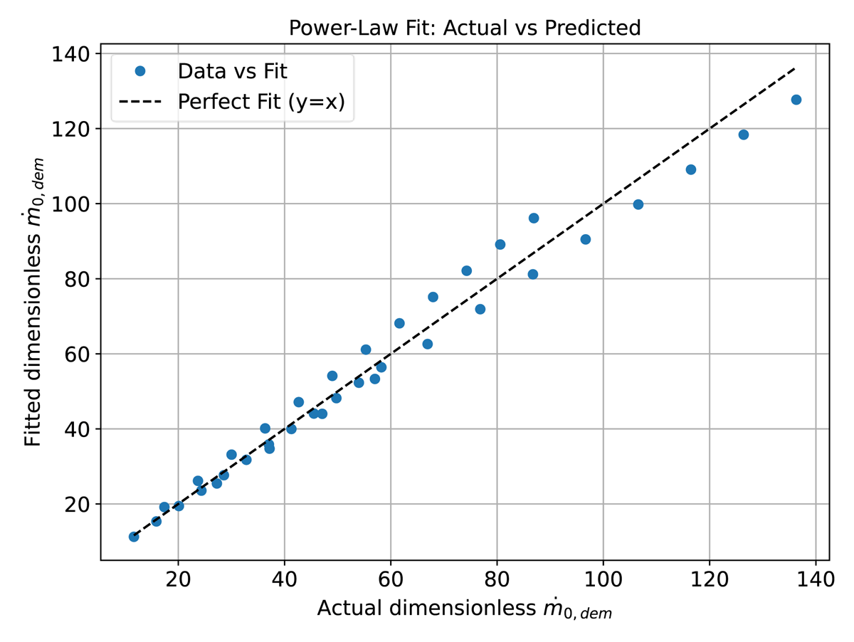
Figure 2
comparison between prediction and experimental data (Saury et al., 2005).
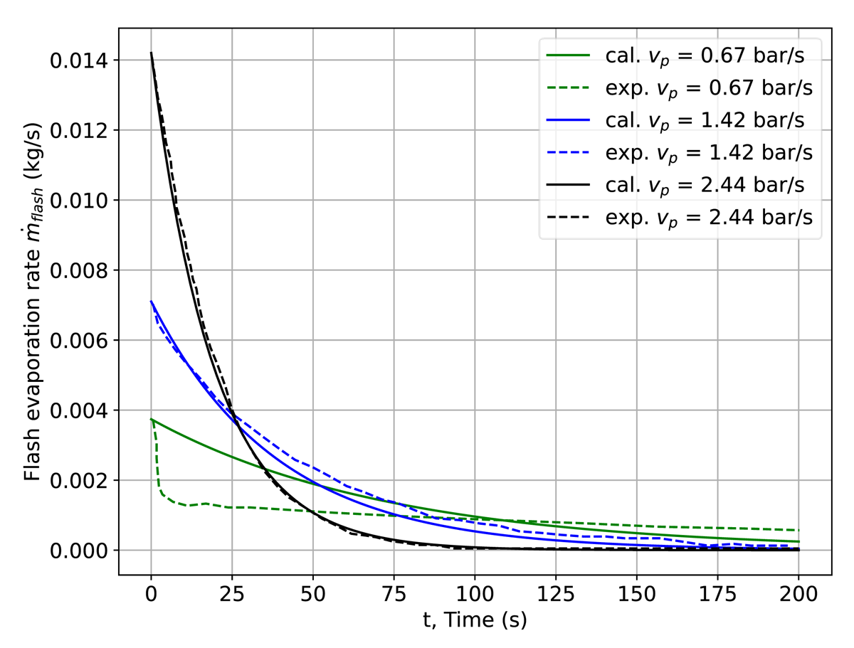
Figure 3
comparison between prediction and experimental data (Saury et al., 2005).
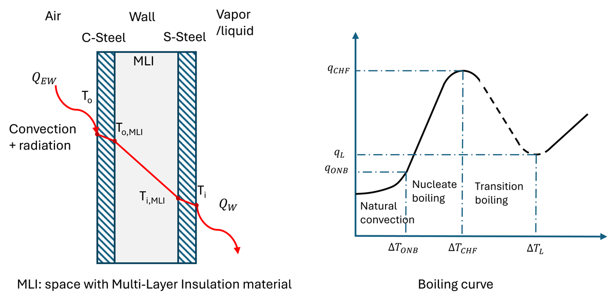
Figure 4
Illustration of heat transfer from wall to fluid.
Table 1
Hydrogen boiling regimes (Machalek et al., 2021; Wang et al., 2016).
| REGIME | ΔT (K) | q̇boiling (W/M2) |
|---|---|---|
| Natural convection (Shirai et al., 2010) | ||
| Nucleate boiling (Kutateladze, 1959) | ||
| Transition boiling (Carey, 2008; Zuber, 1959) | ||
| Film boiling (Breen and Westwater 1962) | |
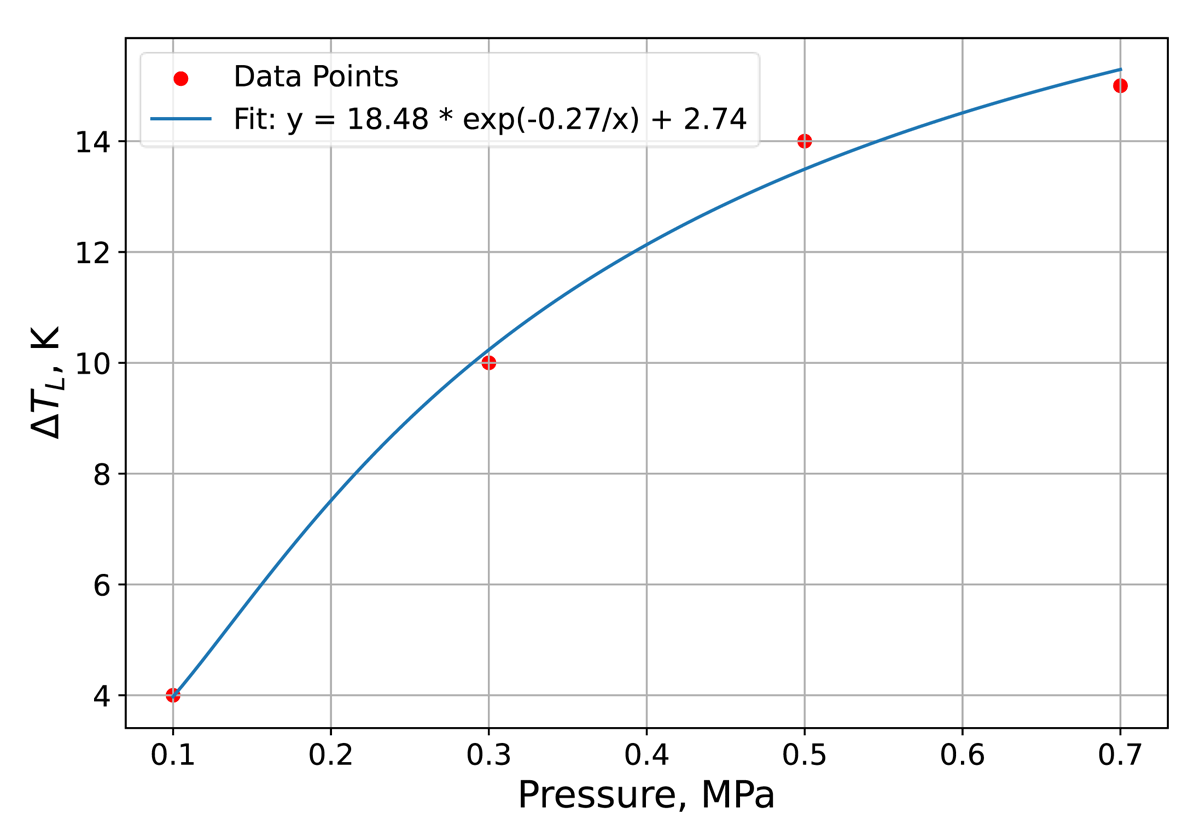
Figure 5
LH2 film boiling threshold vs pressure.
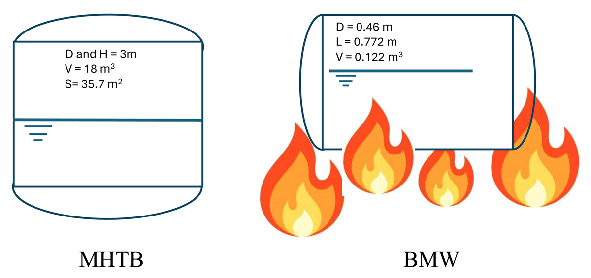
Figure 6
MHTB (vertical) and BMW (horizontal) experiment tanks.
Table 2
Tank walls & isolation properties (Ustolin et al., 2021).
| PARAMETER | INNER WALL, 5083 ALUMINUM | OUTER WALL, AISI 304 STEEL | MLI (VACUUM/AIR/ICE/DEGRADATION) |
|---|---|---|---|
| Thickness (m) | 0.003 | 0.003 | 0.035 |
| Specific heat, Cp (J/kg-K) | 897 | 490 | 1000 |
| Conductivity, 𝜅 (W/m-K) | 120 | 16 | 2.4E-4/2.2E-2/2.0E-1/Function (T) |
| Density, 𝜌 (kg/m3) | 2660 | 7800 | 45/45/100/45 |
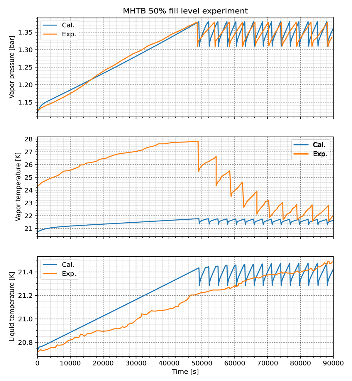
Figure 7
Compare with MHTB experiment.
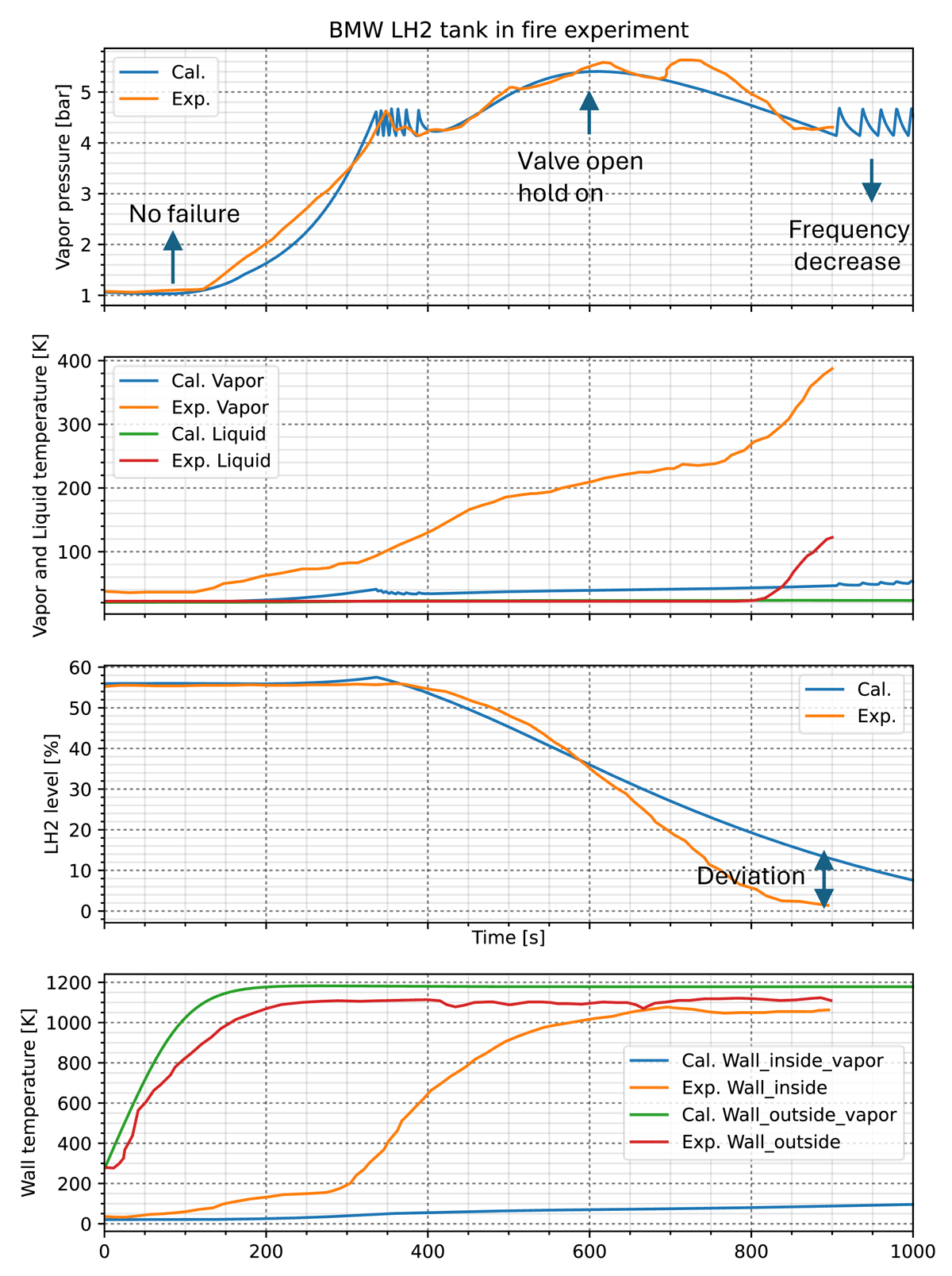
Figure 8
BMW LH2 tank behavior in fire.
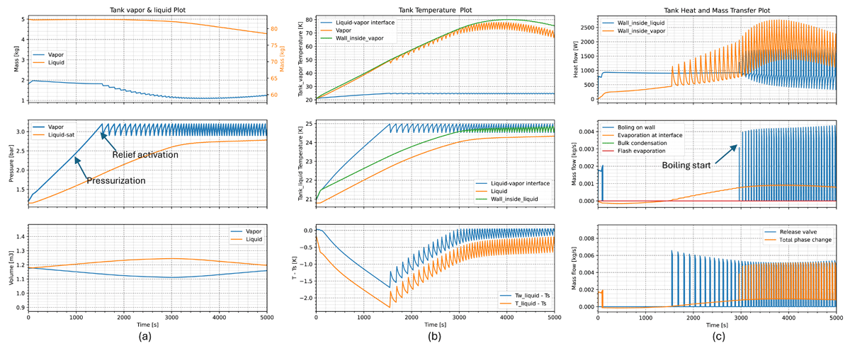
Figure 9
AppLHy! tank parameters when vacuum loss and the space replaced by air.
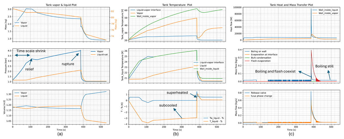
Figure 10
AppLHy! tank parameters when vacuum loss and the space replaced by N2 ice.
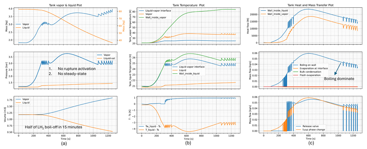
Figure 11
AppLHy! tank parameters when MLI degradation in fire.