
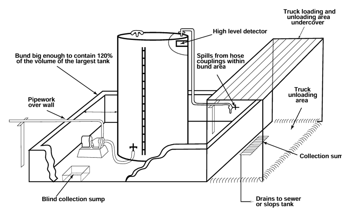
Figure 1
Example of bunding for liquid storage tanks, image source (South Australian Guidelines).
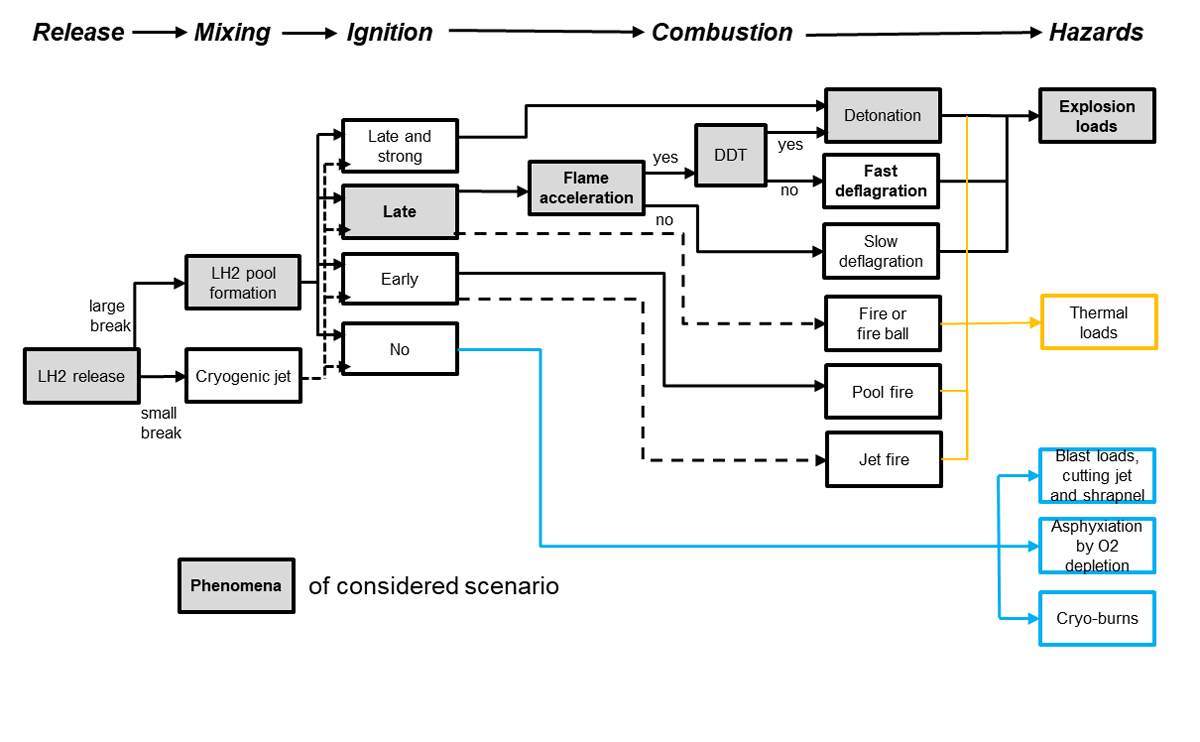
Figure 2
Potential consequences of LH2 release; elements of considered scenario highlighted with grey background.
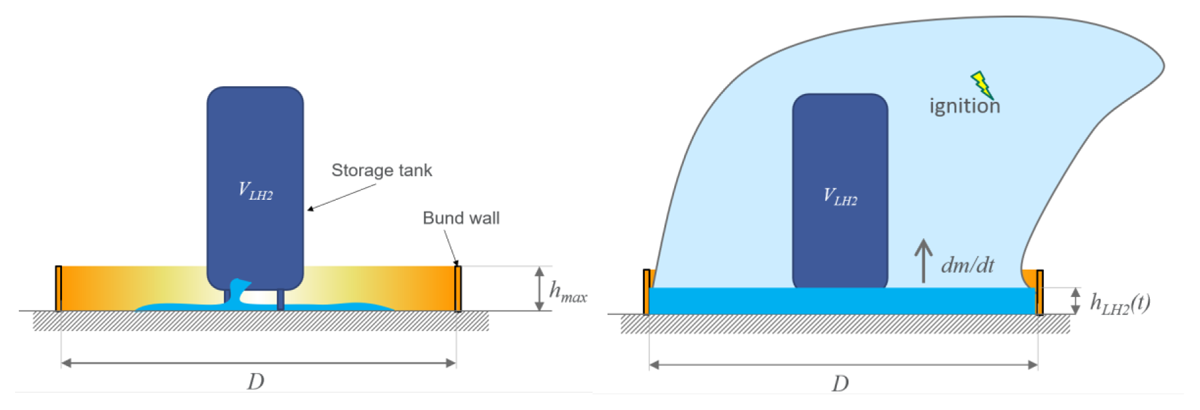
Figure 3
Scenario with initial spilling phase (left) and evaporation phase (right).
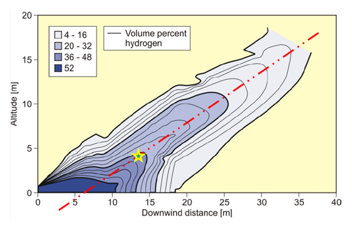
Figure 4
Iso-concentration profiles of the pre-mixed cloud of NASA spill test #6 (Witcofski and Chirivella, 1984).
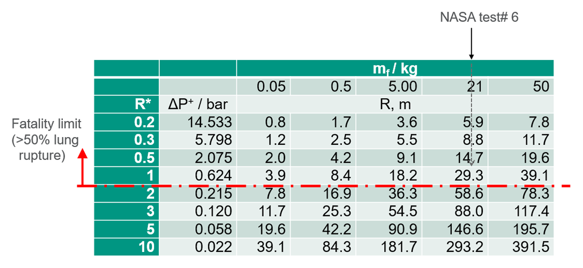
Table 1
Maximum overpressure of fireball with flammable mass mf as a function of the distance R from the centre of the fireball.
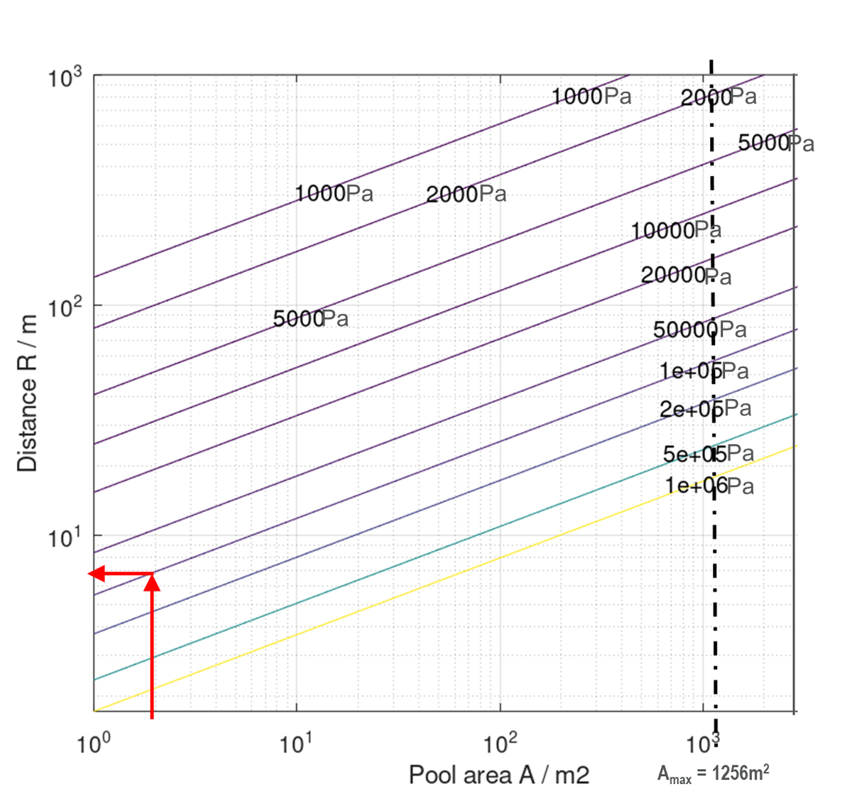
Figure 5
Hazard distance as function of pool surface area and limiting pressure load.
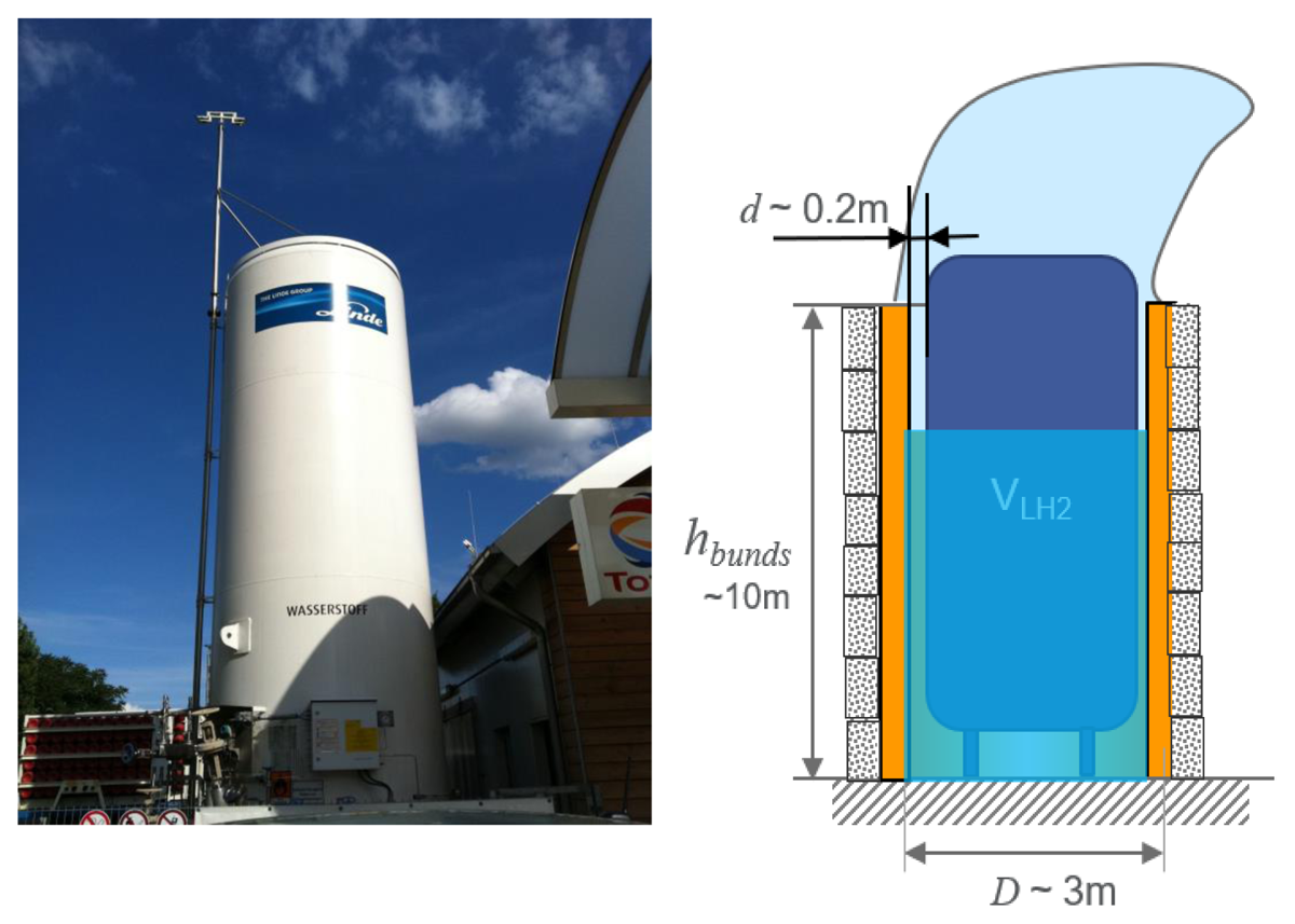
Figure 6
LH2 storage at HRS without bund walls (left); bund walls design for the smallest pool surface area (right).
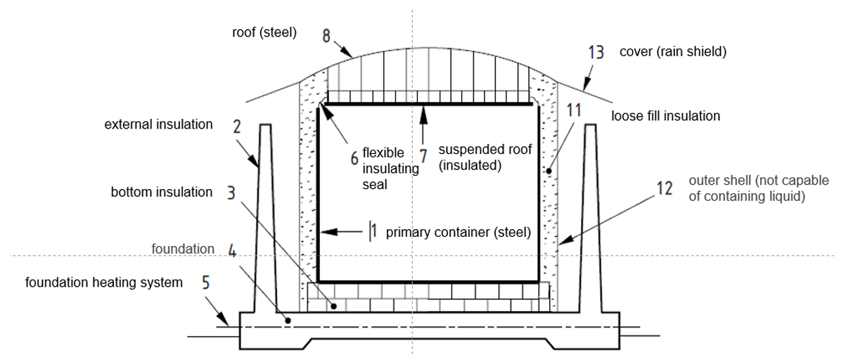
Figure 7
Double containment tank for LNG; image source EN14620.