
1.0 Introduction
For scaling up supply infrastructures, in particular for refuelling larger fleets of hydrogen buses, trucks, ferries, or airplanes, liquid hydrogen (LH2) will be increasingly stored in decentralised large stationary cryostats. Although the use of LH2 cryostats for intermediate storage of larger quantities of hydrogen is widely adopted in the industry, the new siting requirements at refuelling stations close to residential areas raise new safety concerns. For example, in 2024, hydrogen-fuelled buses serving Crawley and Gatwick in United Kingdom were not permitted to operate because of safety concerns over the new LH2 storage installed at the refuelling station (BBC, 2024). The Health and Safety Executive (HSE) has advised against the application due to ‘sufficiently high’ risks. Thus, only up to 10 buses out of a fleet of 20 could be operated using the previously installed, less powerful gas-based refuelling infrastructure. Despite very few reported severe accidents with LH2 and even fewer associated with massive spills of LH2 (Kreiser et al., 1994; HIAD 2.1), an explosion of the associated vapour cloud is obviously being considered a credible scenario. Bunding could mitigate such a scenario, but is currently not considered in the respective guidelines, codes, or standards, which represent the state of the art, further detailed in the following chapter. To provide some arguments for future safety evaluations, in this paper, a simplified model for a hazard analysis will be developed. This model allows determining the mitigation effect of bund walls on the maximum pressure loads of a vapour cloud explosion above an accidentally formed LH2 pool. It will be further motivated why a deterministic approach with regard to the consequences is sufficient and why the probabilistic aspect of risk does not add value. Finally, a high bund wall concept is proposed to mitigate the effects of a vapour cloud explosion below acceptable limits.
2.0 Current State of the Art
Currently, LH2 is stored at low, slightly above atmospheric, sub-critical pressure in cryostats, which are double-wall steel tanks with vacuum and perlite or multi-layer insulation (MLI) in the annular space. This insulation shall limit liquid boil-off caused by heat ingress from the environment. For smaller inventories, the cryostats are cylindrically shaped and installed stationary either with their axis horizontally or vertically. The latter version saves space but is slightly more expensive. For batch transport of up to 4 t of LH2, similar cryostats are mounted on trailers or integrated into robust steel frames with ISO container-compliant mounts. For larger inventories (>50 t), the cryostats are preferentially constructed with spherical shells.
There are mature industry codes (e.g., CGA P-28, EIGA Doc 06/19), a set of ISO standards (ISO 11326, 20421, 21009-13, 21028, 21029, 23208), and even national regulations like US NFPA 52,55 and IGC, dedicated to the safe design and operations of those storage facilities. The ISO TR 15916 provides general safety guidance also for cryogenic hydrogen.
For normal operations, the cryostat is equipped with filling and extraction lines, a level sensor, a pressurisation, and boil-off management system. The latter is typically implemented as a pressure relief valve, keeping the operational pressure well below the maximum design pressure by venting. Additionally, against overpressure, the internal pressure vessel is protected with a safety valve and the external vacuum vessel is protected with a rupture membrane.
For stationary installations of LH2 cryostats, neither dikes nor bund walls are recommended. For instance, the NASA Safety Standard states: ‘The use of dikings or barricades around hydrogen storage facilities should be carefully examined because it is preferred to disperse any leaked or spilled LH2 or SLH2 as rapidly as possible. dikings or berms generally should not be used unless their purpose is to limit or contain the spread of a liquid spill because of nearby buildings, ignition sources, etc’ (Report NSS 1740.15). NFPA-52 2010 Ed, Section 14.3.3 requires with regard to ‘Spill Containment: Diking shall not be used to contain liquid hydrogen spill’. The Air Products Safetygram #9 (Air Products Safetygram #9) advises ‘to locate the liquefied hydrogen container on ground higher than flammable liquid storage or liquid oxygen storage. Where it is necessary to locate the liquefied hydrogen container on ground that is lower than adjacent flammable liquid storage or liquid oxygen storage, suitable protective means (such as diking, diversion curbs, or grading) should be taken’ and the Florida Compressed Gases and Cryogenic Fluids Code 2020: ‘11.3.1.2.1 Diking shall not be used to contain a liquid hydrogen spill. 11.3.1.2.2 Diking or berms shall be permitted to direct the spill away from exposures’.
In case of a massive LH2 spill, omitting bund walls should allow for maximum pool spreading and thereby support the fastest evaporation via the large pool surface. This implies, however, that in these scenarios, huge pre-mixed cold clouds evolve close to ground level with a potential for strong explosive loads, at least for a relatively short time. This safety strategy is different for liquid fuels and even LNG, where bunding, as depicted in Figure 1, is required normally.
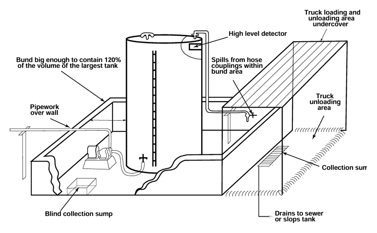
Figure 1
Example of bunding for liquid storage tanks, image source (South Australian Guidelines).
In the following, the considered worst-case scenario ‘Large LH2 spill’ is defined, for which then a simplified model is developed, which allows to determine the consequences and mitigation effect of bund walls.
3.0 Scenario
A loss-of-containment accident scenario associated with a large spill release of LH2 is assumed. The assumed escalating event sequence is highlighted by the grey boxes in the event graph shown in Figure 2. Either by equipment or operational failure, improper installation or external hazards like fire, impact or by a malicious act a loss of containment of the actual cryostat or a major break of the main LH2 supply/extraction lines occurs. A relatively high flow rate, a low release point, and a downward-oriented release direction all contribute to the spilled LH2, forming a pool.
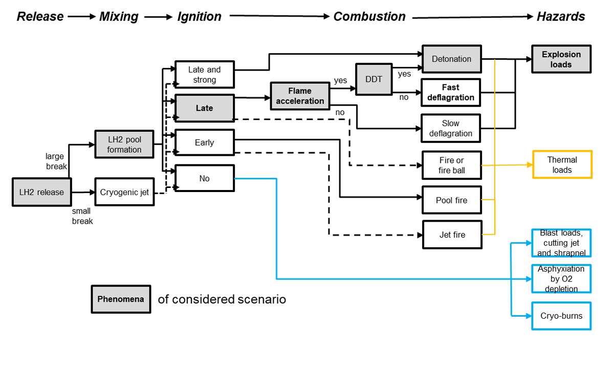
Figure 2
Potential consequences of LH2 release; elements of considered scenario highlighted with grey background.
The pool, which spreads either freely or is limited by bund walls, will evaporate and form a cold hydrogen-air plume above the pool, eventually displaced by side winds. A delayed ignition of this vapour cloud is assumed, leading to an explosion. The initial, non-reactive part of the scenario is artificially split into two main phases: the spill and the subsequent evaporation phase (see Figure 3).
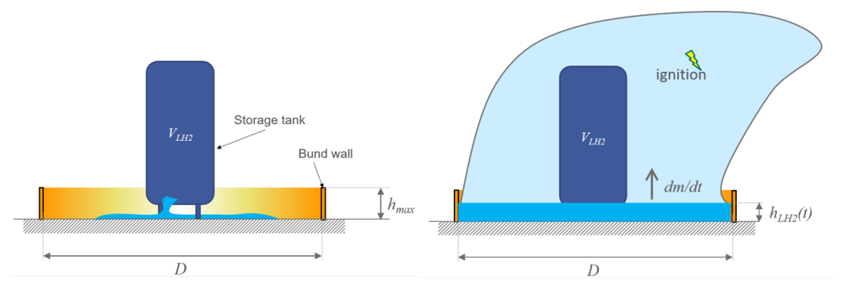
Figure 3
Scenario with initial spilling phase (left) and evaporation phase (right).
The probabilities for this extreme scenario are considered low. Pool formation, for instance, was only reported for a single case of the 113 cases related to LH2 of the total 954 accidents in the EC JRC Hydrogen Incident and Accident Database (HIAD) (HIAD 2.1). In HIAD also only one detonation of cryogenic hydrogen is reported during boil-off venting (case 369). No spontaneous ignition was observed in many hundred release and pool experiments performed in the PRESLHY project (Jordan et al., 2021).
3.1 Further conservative assumptions
(1) The spilled LH2 with the volume VLH2 instantaneously covers the area A, which is enclosed by the bund walls installed at a characteristic distance D. Therefore, the initial height of the pool is
This assumption of a delayed evaporation starting at time t = 0 will maximise the size of the pool and of the evolving vapour cloud. The same assumption is used for determining the actual bund wall height according to the standards, for instance (South Australian Guidelines), where the maximum stored liquid inventory increased by 10% should be retained by the bund walls reliably. The minimum distance D is given by the dimensions of the storage system itself; the maximum distance is either given by spatial constraints or by the naturally limited pool spreading. In Verfondern (2008), the latter is given as 40 m for a release rate of 1 m3/s lasting for 40 s.
(2) The pool height degression or boil-off rate BOR, measured in mm/s, is assumed to be constant. This implies a constant boil-off mass flow rate, dm/dt. The evaporation phase starts at t = 0 and lasts until the pool height reaches ground level at t = tmax.
with ρ = 70 g/l and
(3) The constant mass flow rate will immediately generate a stationary flammable cloud with a constant flammable mass mf
with τ representing a characteristic atmospheric mixing time.
Assumptions (2) and (3) are conservative as they maximise the time of persistence of the pre-mixed cloud with maximum flammable mass.
(4) Ignition of the stationary pre-mixed cloud is assumed at any time t = 0 .. tmax. This is conservative, as spontaneous ignition of cryogenic cold clouds is statistically very unlikely.
(5) Loads are determined by a fireball correlation assuming detonation as the combustion regime. This may appear overly conservative at first glance. However, recent experimental work (Jordan et al., 2021) and fundamental analysis of detonation sensitivity show that the propensity for deflagration-to-detonation transition (DDT) in cold or even cryogenic pre-mixed clouds is relatively high.
4.0 Consequence Analysis
4.1 Flammable mass in the vapour cloud
With the above assumptions, the pool height degression rate BOR is first determined empirically by published data. In the PRESLHY spill experiments on a 0.5 m × 0.5 m pool with sand and concrete as ground materials, Friedrich et al. (2023) observed a relatively constant rate of 3.77 mm/s within the first 24 s. In the later phase, the degression rate dropped to about 0.56 mm/s. Takeno et al. (1994) observed 2–2.7 mm/s in the early phase (t < 13 s), decreasing later to 0.5 mm/s (t > 30 s) for a top open cylinder with 100 mm inner diameter. In Bailey et al. (1960), values of maximum 2–3 mm/s and 0.63 mm/s at the minimum are reported and in Annex B.1 of ISO TR 15916:2015, 1.1 mm/s and 0.5 mm/s at the minimum. The enveloping upper limit derived from these data is set to
what is considered conservative, as most of the experimental data are derived from relatively small experiments with relatively high heat ingress into the pool.
As in the model, the flammable mass depends only on the constant pool height degression rate BOR and the surface of the pool A, the model can be calibrated based on the relatively well-documented NASA spill test #6 (Witcofski and Chirivella, 1984). In this test, LH2 with VLH2 = 5.11 m3 was released in 35 s on a circular pad with a diameter of 9.1 m. With (2) and (5), and the surface A, the boil-off mass flow rate is determined as
This characterises the evaporation phase, which is actually controlled by the atmospheric conditions of the NASA test #6. The duration of existence of the pool is estimated to be 27 s. This is derived from the initial time of full pool establishment, assumed to be associated with the photo at 15.95 s and the reported total evaporation at 43 s after start of the release, i.e., 8 s after the end of the spilling. The duration of existence of the cloud with maximum size is estimated to be 27 s as well. This value is derived from the frame taken at 27.92 s and the last frame at 55.12 s after the start of the release, corresponding to 20 s after the stop of the release. These 27 s correspond surprisingly well with the 26.2 s derived from Equation (3). The characteristic shape and concentration isolines of the cloud with maximum size are depicted in Figure 4.
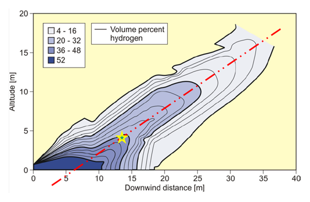
Figure 4
Iso-concentration profiles of the pre-mixed cloud of NASA spill test #6 (Witcofski and Chirivella, 1984).
The flammable mass is derived by estimating the volume of the s-cloud, that is, the part of the pre-mixed cloud where concentrations are sufficiently high to sustain flame acceleration. Accounting for the reduced temperatures in the cloud and assuming axis symmetry of the cloud around the red dotted line in Figure 4, the flammable cloud volume Vf is estimated to be 750 m3 with an average hydrogen concentration of 30%. This yields a flammable mass mf of about 21 kg. Inserting this and (6) in (4) yields τ = 1.54 s and finally provides a simple correlation for the maximum flammable mass, depending on the pool area A only:
4.2 Maximum loads of the vapour cloud explosion
Assuming a central ignition of the flammable cloud close to the stochiometric conditions (see yellow star in Figure 4), the flammable mass would generate a fireball with a diameter of about 13.6 m according to the correlations of Kuznetsov et al. (2023). This fireball would reach locations on 2 m height up to a distance of 10 m from the edge of the pool. More severe are the corresponding pressure loads, which are determined with the following correlations, see (Kuznetsov et al., 2023):
with dimensionless radius , over-pressure and positive impulse defined by
with initial atmospheric pressure P0, the speed of sound in air c0, and reaction enthalpy ΔH.
Table 1 lists the maximum overpressure relation for different flammable masses including the 21 kg for NASA test #6. For different limit loads, like 1 bar over-pressure for a 50% lung rupture, hazard distances are easily derived from this table. For the NASA test# 6, this hazard distance is about 30 m from the point of ignition.
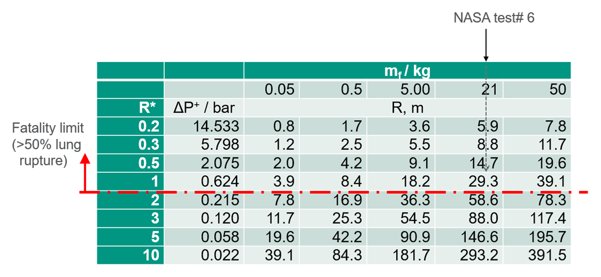
Table 1
Maximum overpressure of fireball with flammable mass mf as a function of the distance R from the centre of the fireball.
5.0 Some Aspects Concerning Risk
With the simplified model introduced above, the pressure loads of a vapour cloud explosion above LH2 pools may be conservatively estimated, using only the pool surface area. As the flammable mass is linearly increasing with the pool surface area, the current recommendations of no bunding would allow for maximum explosive loads. This is justified by claiming a reduced ignition probability with the minimised time of exposure, time of existence of the large premixed cloud, respectively. However, the large flammable cloud is enclosing a larger volume Vf containing a correspondingly larger number of potential ignition sources.
Associating probabilities with the key phenomena of the event tree in Figure 2, the integral probability of the considered scenario is derived as
with the probability of the initiating event ‘loss of containment leading to pool formation’ pLOC and the probability for a late ignition pign.
A reduction of the pool area A via bunding increases tmax according to Equation (3) and, on the other hand, decreases the flammable mass mf and flammable volume Vf according to Equation (4). An increase of the pool area will have opposite, mutually compensating effects. So, it may be concluded that the pool area has only subordinate influence on the ignition probability. This implies that the risk is controlled by the consequences only, and minimising the risk is achieved by minimising the pool area.
This implies that the overall approach for the safety evaluation of large LH2 storage becomes a rather deterministic approach. It consists of the determination of the worst credible scenario and of mitigating its consequences to acceptable load limits without using a probability database, which is lacking anyway. Incidentally, it is common practice to remove extreme scenarios from probabilistic considerations and examine them instead in a deterministic analysis.
6.0 Application of the Model
The suggested model allows to determine hazard and safety distances with two simple steps. First, we determine the flammable mass with the LH2 pool surface area. Then, with the flammable mass, we determine the maximum overpressure. Figure 5 summarises this approach. With the pool surface area and the limiting pressure load, shown as isobaric lines in Figure 5, the hazard distance can then be read directly on the y-axis.
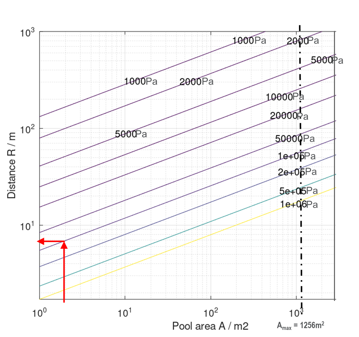
Figure 5
Hazard distance as function of pool surface area and limiting pressure load.
This simple conservative model is applied to a prototypical LH2 storage at a hydrogen refuelling station (HRS). The reference installation is a vertically installed cryostat at an HRS operated in Berlin, Germany, see Figure 6 (left). The installation did not foresee any bunding. So, for the considered scenario, a LH2 pool with a maximum diameter of 40 m (maximum surface area 1256 m2) has to be considered, which might generate a pre-mixed cloud with a flammable mass of more than 400 kg, correlating to about 10% of the stored LH2 mass.
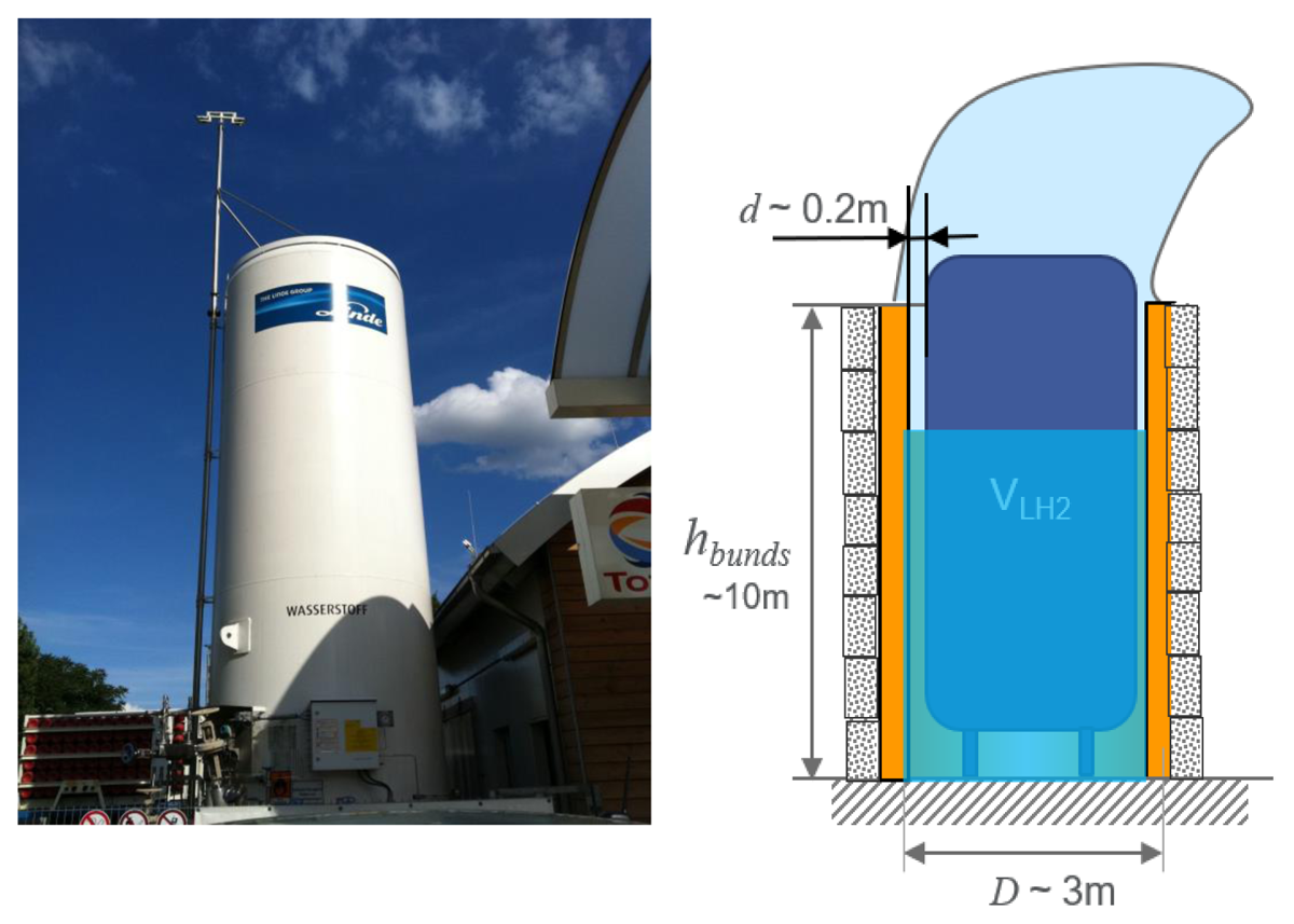
Figure 6
LH2 storage at HRS without bund walls (left); bund walls design for the smallest pool surface area (right).
The bunding wall design, which ensures minimal accidental pool surface area, will be a degenerated bund wall, rather than an additional enclosure or containment, which is open at the top, see Figure 6 (right).
Assuming the gap between cryostat and bund wall is technically limited to 0.2 m, the free annular surface of the pool is approximately 2 m2. Equation (7) gives a maximum flammable mass of 0.65 kg for such a configuration. The distance to 1 bar overpressure would be reduced to approximately 7 m, see red arrows in Figure 5. Accounting for the high release point of about 10 m, the hazard distance would be reduced significantly. The distance for glass breaking (over-pressure ~ 20 mbar) would be reduced to 100 m; without the bund walls, the scenario with freely spreading pool would give a hazard distance of about 900 m for this limit.
Such bund walls could be composed of an inner metallic cylinder and some heat-insulating material like stone wool or vacuum-insulated panels (VIPs) attached on the outside. This design would provide additional protection against external hazards, like fires. Without the heat insulation on the high bund walls, the assumption of a boil-off rate depending only on the pool surface area is not valid any more. The intensified heat ingress will lead to much higher boil-off rates, which do not allow the simple model to be used without further adjustments.
However, this proposal resembles quite closely the modern design of an LNG tank as referred to by the European Standard EN14620 (see Figure 7).
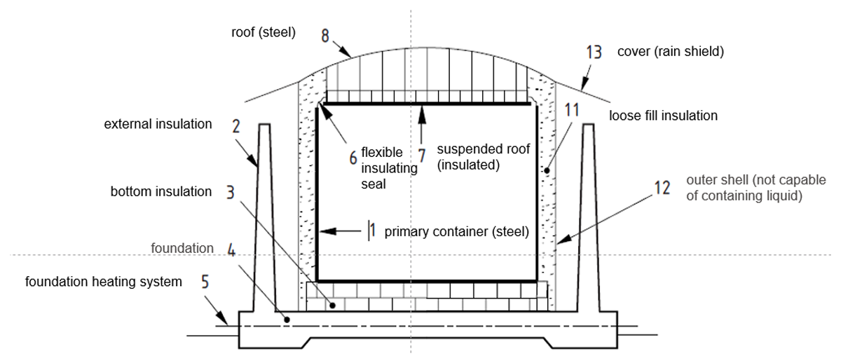
Figure 7
Double containment tank for LNG; image source EN14620.
The double containment tank consists of a primary inner cryo-container and a secondary container, open at the top. The standard requires the secondary container to be designed to hold all liquid in case it leaks.
Underground storage offers another alternative for minimising accidental boil-off. A buried tank design would allow for operational intervention on ground level with all interfaces installed in an enclosure on the top of the tank. Installing a horizontally aligned cryostat in a vault would provide better access and use of conventional pumps, but it comes at higher costs.
7.0 Conclusions
Obviously, loss of containment of stationary LH2 storage is a concern for authorities, partially because the accidental behaviour of cryogenic hydrogen and the effect of mitigation measures, like bund walls, are not yet well understood. The suggested simple and conservative model allows to determine the maximum boil-off rate and flammable mass above the pool generated by a massive leak of LH2. The model is based on published pool height degression rates and calibrated with a representative large-scale experiment performed by NASA in the 1980s. Several assumptions regarding the involved phenomena have been introduced to provide a very easy and conservative estimate for maximum pressure loads associated with a vapour cloud explosion. The only input parameter is the pool surface area.
For smaller pools the ignition probability is increased by a longer evaporation period but simultaneously decreased by a smaller flammable cloud volume. So, the overall probability for such an event seems to be independent of the LH2 pool surface area. On the other hand, the maximum pressure loads are strongly correlated with the pool surface area and significantly decrease with a smaller pool size. The postulated invariance of the probabilities allows avoiding a probabilistic approach and rather turns the attention to reducing the maximum loads below acceptable limits, deterministically.
This model has been applied to a prototypical LH2 stationary storage system of refuelling station. The results show that with quite narrow bunds, resembling the secondary containment of modern LNG tanks, consequences can be limited to acceptable levels. Besides, such a secondary containment can serve as a protective wall against external hazards.
8.0 Outlook
Future work should check the calibration of the model and investigate a wider range of weather conditions. Also, the hypothesis of invariant ignition probabilities should be examined more carefully. The actual design, construction details, and the influence of the bund walls and the storage cylinder itself on the cold vapour cloud dispersion should be analysed further, partially referring to other publications like (Sun et al., 2021), for instance. Obviously, the compatibility of the suggested solution with other, more probable scenarios should be evaluated.
By no means does this work question the safety of established installations. It is rather meant for new installations, in particular in residential areas or close to other fuel tanks, where the risks are considered unacceptable by the authorities having jurisdiction.
With the proposed simple but conservative—possibly still quite over-conservative—correlations, the hazards, and implicitly, the corresponding risk associated with a severe loss of containment accident and the mitigating effects of bunding may be determined in corresponding risk assessments. In critical cases, bunding might reduce hazard distances and allow for a safe installation in sensitive environments.
Competing Interests
The lead author is editor of the journal and therefore delegates all processing and decisions to the deputy editor-in-chief, who is free of any conflict of interests.