
Table 1
Experiments available in the open literature dealing with hydrogen storage tank bursts.
| N° | H2 STATE | TANK TYPE | TANK V. (L) | TANK POSITION | TANK SIZE L/D (M) | TANK INITIAL P. (MPa) | TANK BURST P. (MPa) | TANK BURST TEMP. (K) | BURSTING METHOD | REF. |
|---|---|---|---|---|---|---|---|---|---|---|
| 1 | LH2 | LH2 | 120 | H | 0.722/0.46 | 0.5 to 1.48 | 0.5 to 1.48 | 20 | Cutting charge | (Pehr, 1996) |
| 2 | GH2 | 1: IV 2: III | 1: 72.4 2: 88 | 1: H 2: under a SUV | 0.84/0.41 | 1: 34.3 2: 31.8 | 1: 35.7 | 1: 312.15 | Fire | (Zalosh & Weyandt, 2005), (Zalosh & Wellesley, 2007) |
| 3 | GH2 | 1: IV 2: III | 1: 35 2: 36 | H | N.P.* | 1: 70.23 2: 70.69 | 1: 94.54 2: 99.47 | 1: 379.8 2: 394.2 | Fire | Cited in (Molkov, et al., 2021) |
| 4 | GH2 | III | 9 | H | N.P. | 70 | 70 | N.P. | Cutting charge | (López, et al., 2015) |
| 5 | GH2 | IV | V corresponding to 2.1 kg of CGH2 | In a vehicle | N.P. | 70 | N.P. | N.P. | Fire | (Park & Kim, 2023) |
| 6 | GH2 | III | 165 | N.P. | 1.775/0.37 | 35 | 43.8 to 44 | N.P. | Fire | (Shen, et al., 2018) |
| 7 | GH2 | III | 6.8 | V | 0.52/0.157 | 30.6/31.0 | 49.7±3.3 | N.P. | Fire | (Wang, et al., 2023) |
| 8 | LH2 | LH2 (MLI) | 1000 (filling 35–40%, 27 kg of LH2) | H | N.P. | 0.4 | 5 | 26.2–32.4 (estimated) | Fire | (van Wingerden, et al., 2022) |
| 9 | GH2 | IV | 580 | H | 2.06/0.686 | 25 | 25 | 288.15 | projectile | (Brooks & Glover, 2022) |
[i] *N.P. Not Provided.
Table 2
Proposed values of energy contribution in blast wave formation.
| N° | α | β | REFERENCE |
|---|---|---|---|
| 2 | 1.8 (tank only) 0.12 (under vehicle) | 0.042 0.09 (under vehicle) | (Weyandt, 2007) |
| 3 | 4 | 0.052 | Cited in (Molkov, et al., 2021) |
| 6 | 1.8 | 0.052 | (Shen, et al., 2018) |
Table 3
Experiments available in the open literature dealing with fireballs after CGH2 storage tank bursts.
| N° | FIREBALL DIAMETER (M) | FIREBALL DURATION (S) | REF |
|---|---|---|---|
| 2 | 7.7 (momentum driven 45 ms after rupture), 16.5 (CFD simulation of [5]) 24 (no time provided) | Lift-off at 1 s Visible 2s, IR 4.5 s | (Zalosh & Weyandt, 2005), (Zalosh & Wellesley, 2007) |
| 3 | 20 | Cited in (Molkov, et al., 2021) | |
| 6 | 7 to 8 | 1.2 | (Shen, et al., 2018) |
| 7 | 4.48 (Test 1) 4.62 (Test 2) | 0.127 (momentum) 2 (buoyancy) | (Wang, et al., 2023) |
Table 4
Test conditions for catastrophic rupture of CGH2 tanks in open atmosphere.
| TEST N° | P(MPA) T (K) | TYPE | V (L) | WEIGHT (KG) | L/D (M) | CUTTING CHARGE LOCATION | PHOTO |
|---|---|---|---|---|---|---|---|
| 4 | 52 to 54 296 | IV | 6 × 240 | 6 × 219 + Frame | 2.575/0.48 | Between two tanks | 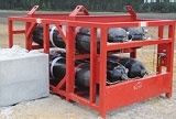 |
| 6 | 53 298 | IV | 240 | 219 | 2.575/0.48 | Centred | 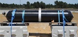 |
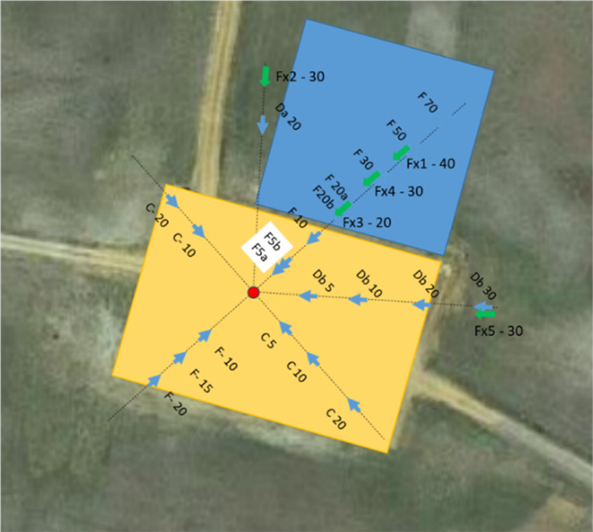
Figure 1
Arrangement of blast sensors (C, F, Db and Da) and radiometers (Fx) at the test site.
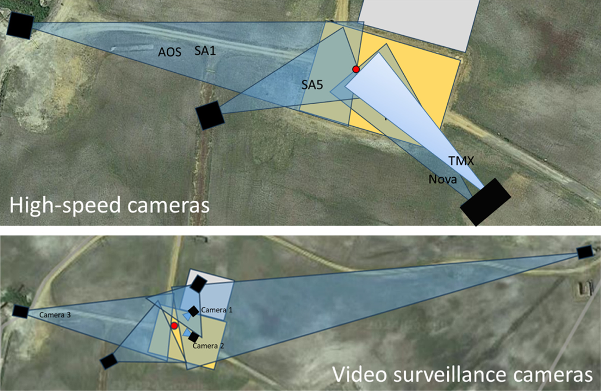
Figure 2
Arrangement of cameras at the test site.
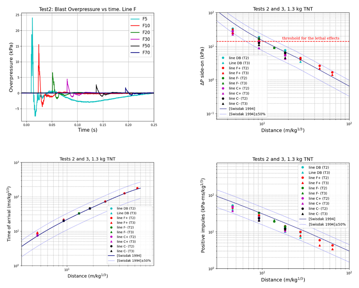
Figure 3
Tests 2 and 3 (1.3 kg of TNT). Overpressure evolution with time along the line F (Test 2) (top left), maximum overpressure (top right), blast wave time of arrival (bottom left), and positive impulse (bottom right) along different lines.
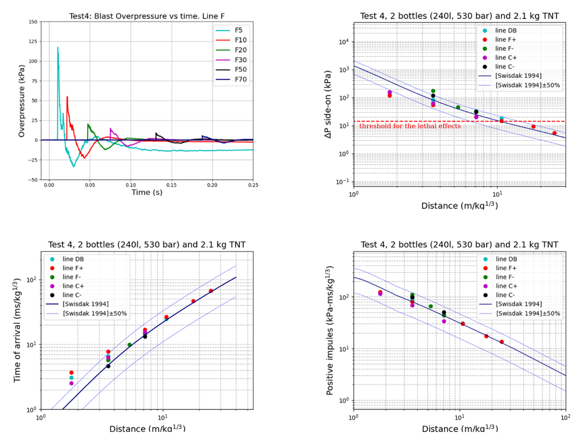
Figure 4
Test 4. Overpressure evolution with time along the line F (top left), maximum overpressure (top right), blast wave time of arrival (bottom left), and positive impulse (bottom right) along different lines.
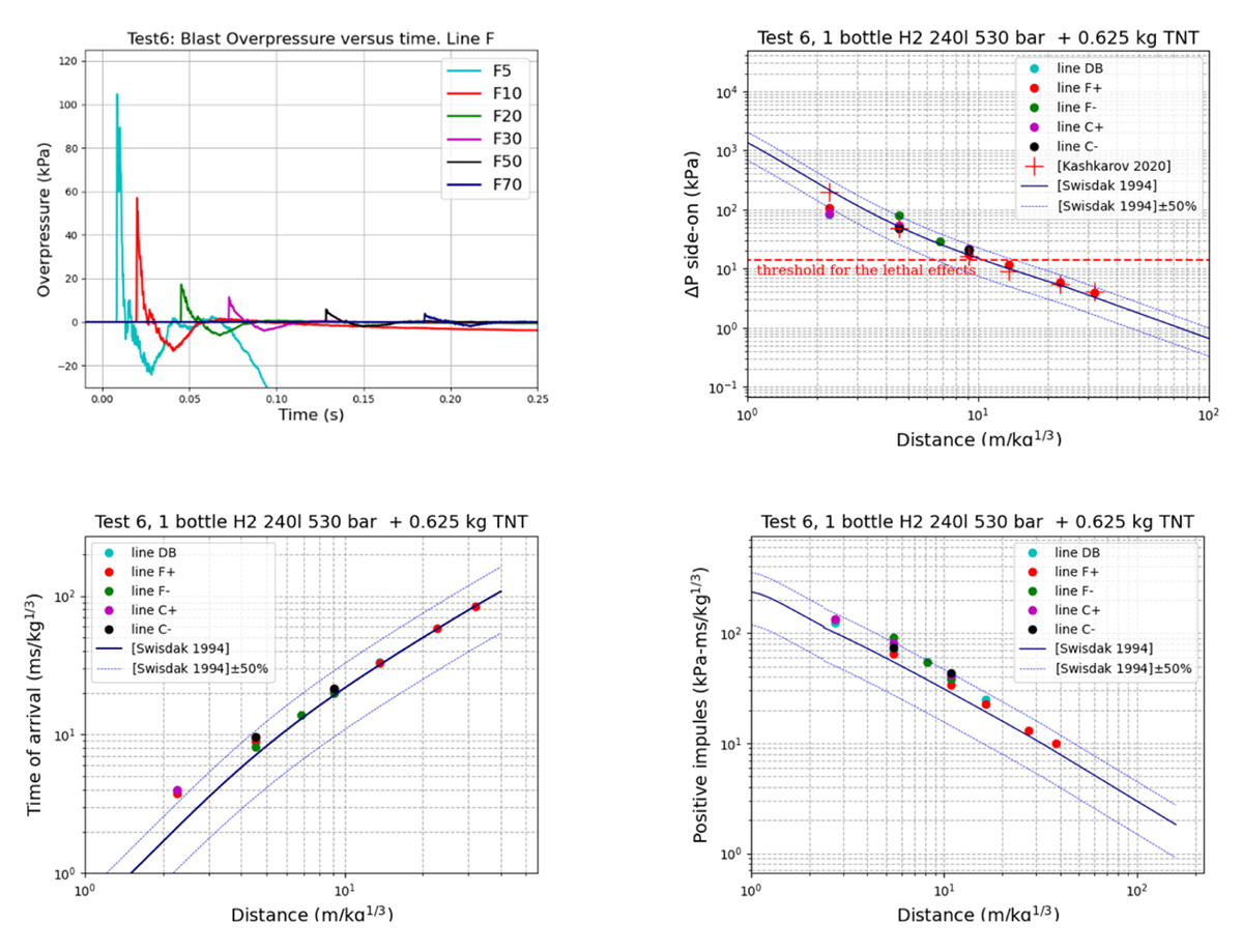
Figure 5
Test 6. Overpressure evolution with time along the line F (top left), maximum overpressure (top right), blast wave time of arrival (bottom left), and positive impulse (bottom right) along different lines.
Table 5
Mass and energy values in kg TNT corresponding to the Test 4 and 6. SE, Solid Explosive; mech, Mechanical; chem, Chemical. 1kg TNT = 4.184 MJ.
| TEST N° | MSE, KG TNT | MH2, KG | EMECH, KG TNT | ECHEM, KG TNT |
|---|---|---|---|---|
| 4 | 2.1 | 15.6 | 11.1 | 448 |
| 6 | 0.625 | 7.78 | 5.55 | 224 |
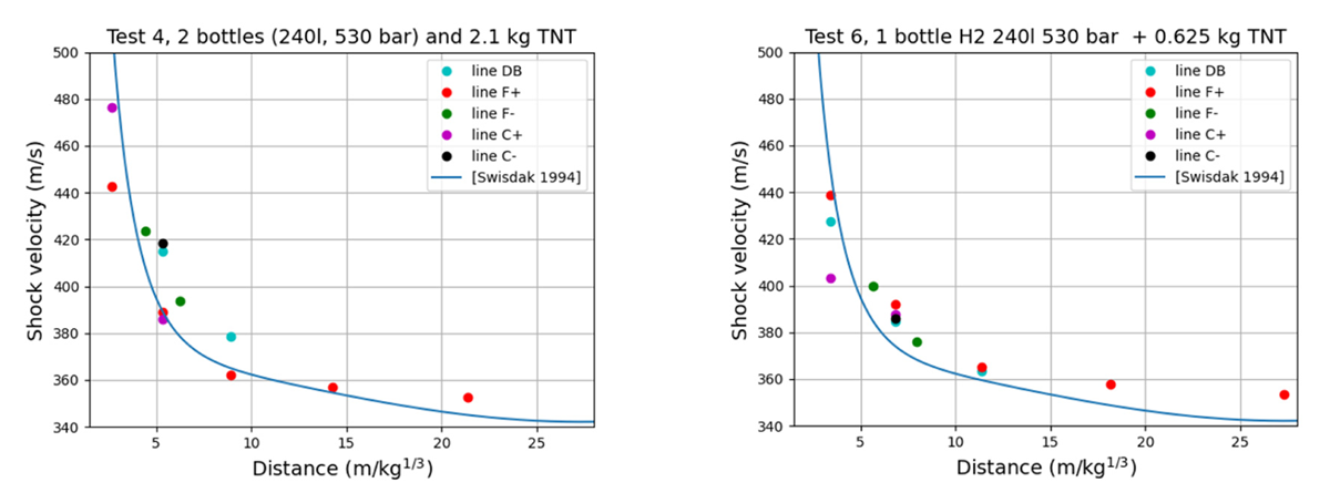
Figure 6
The blast wave velocity evolution with distance for Test 4 (left) and Test 6 (right).
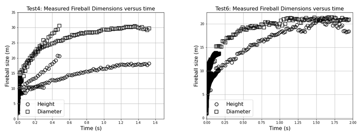
Figure 7
Fireball development: left, Test 4 (after 0.5 s, the fireball leaves the field of view of one of the cameras); right, Test 6.
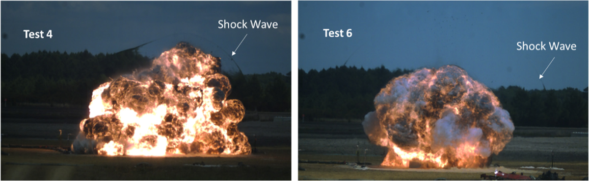
Figure 8
Fireball shape after about 10 ms (Photron SA1 camera).
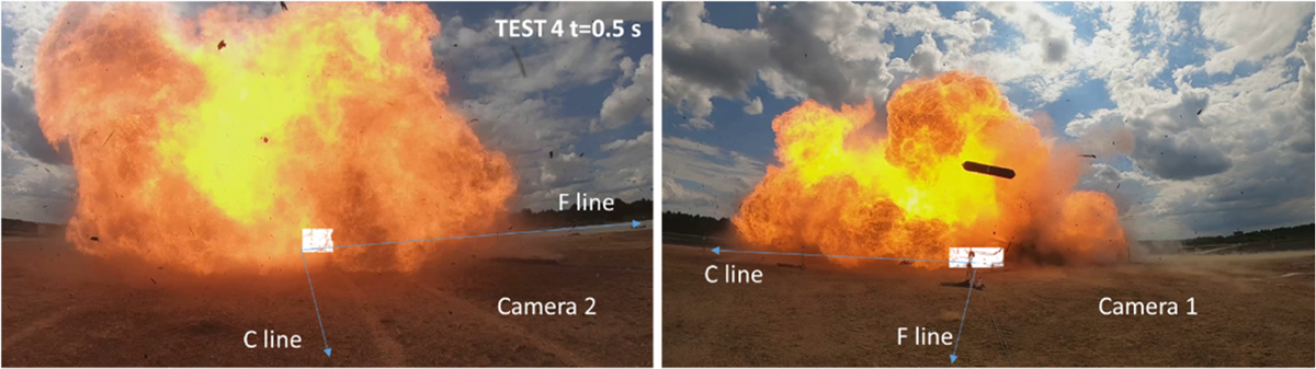
Figure 9
Test 4: fireball shape at 0.5 seconds (cameras 1 and 2).
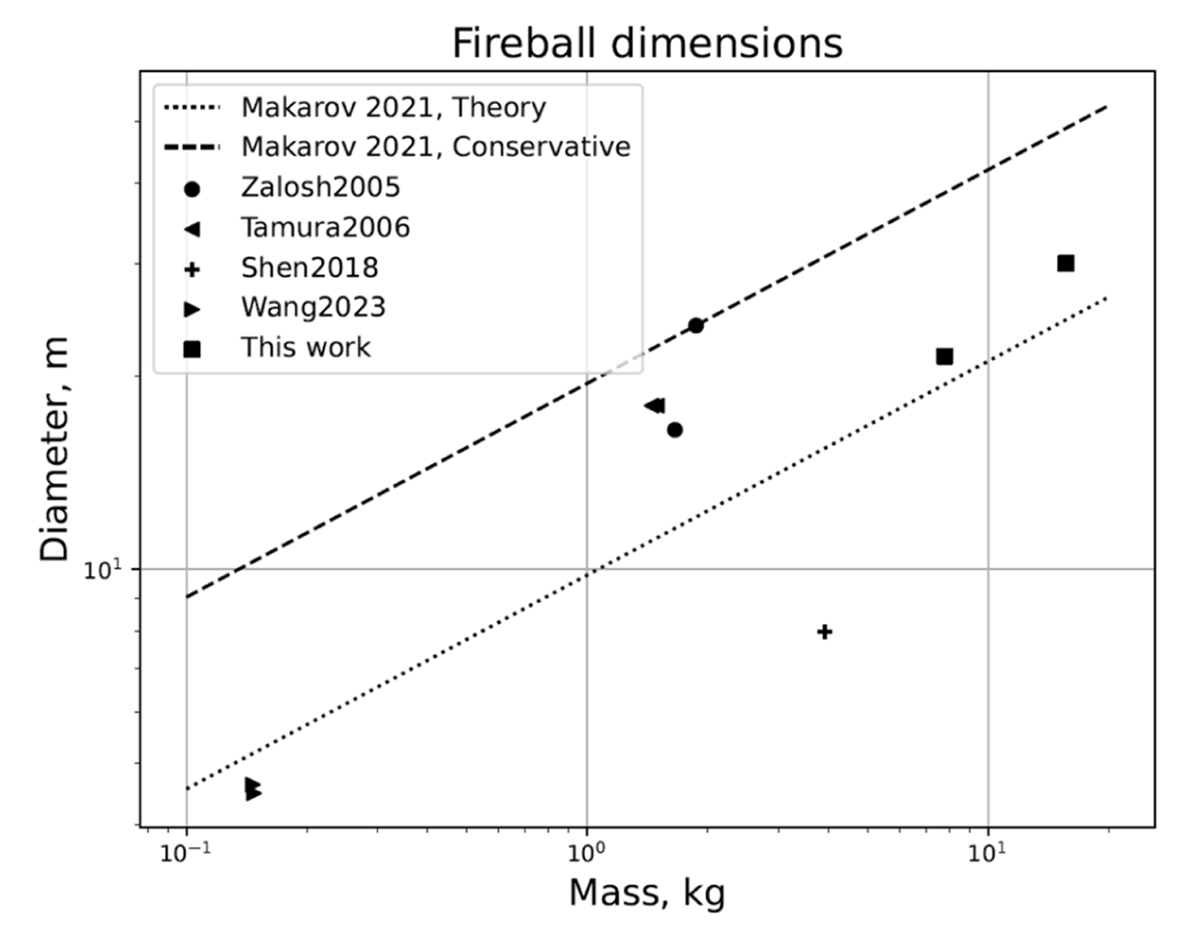
Figure 10
Synthesis of fireball dimensions in cases of CGH2 bursting tanks.
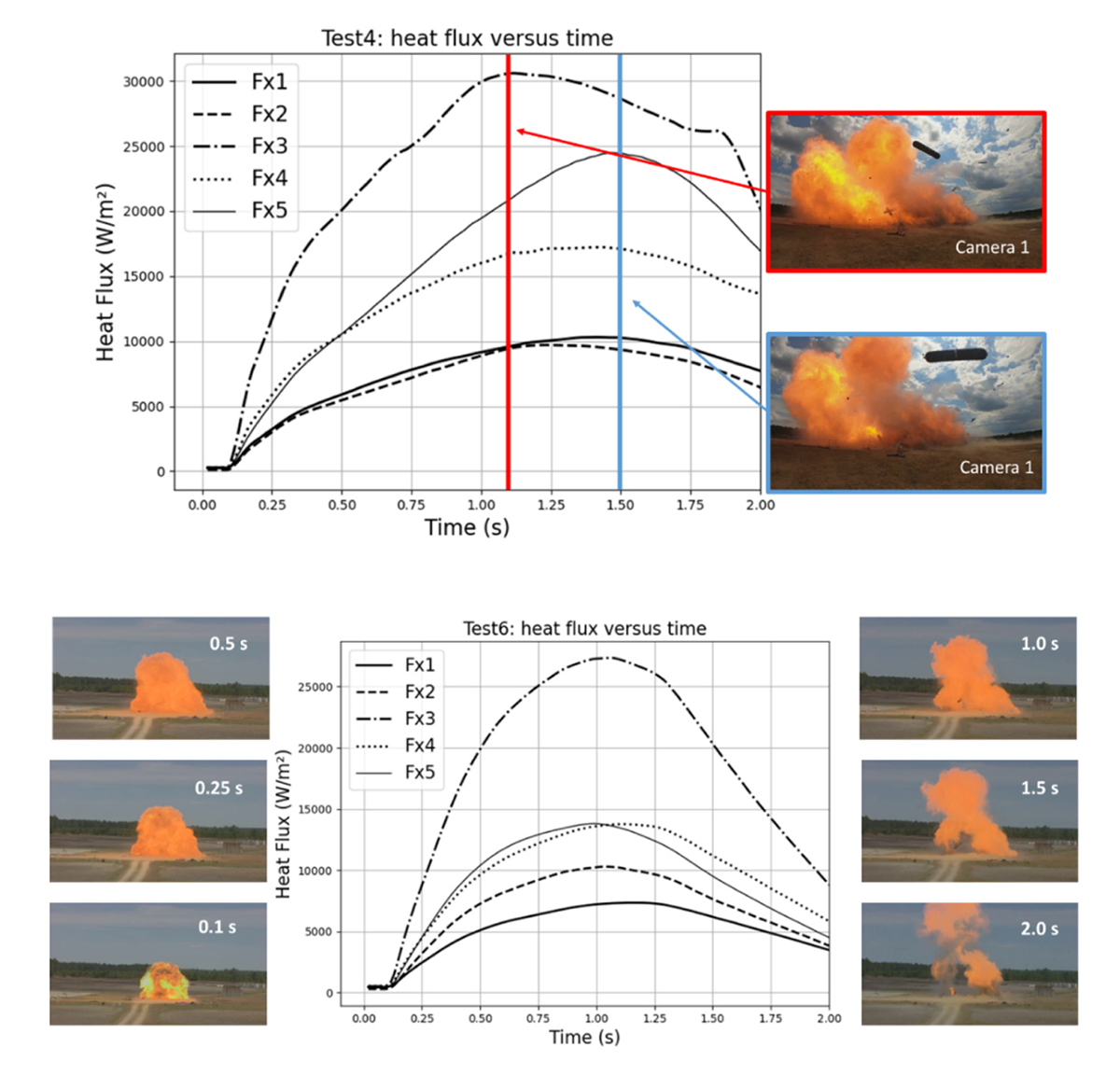
Figure 11
Fireball shape and associated radiated heat fluxes. Top: Test 4 (cameras 1 and 2); bottom: Test 6 (camera 3).