
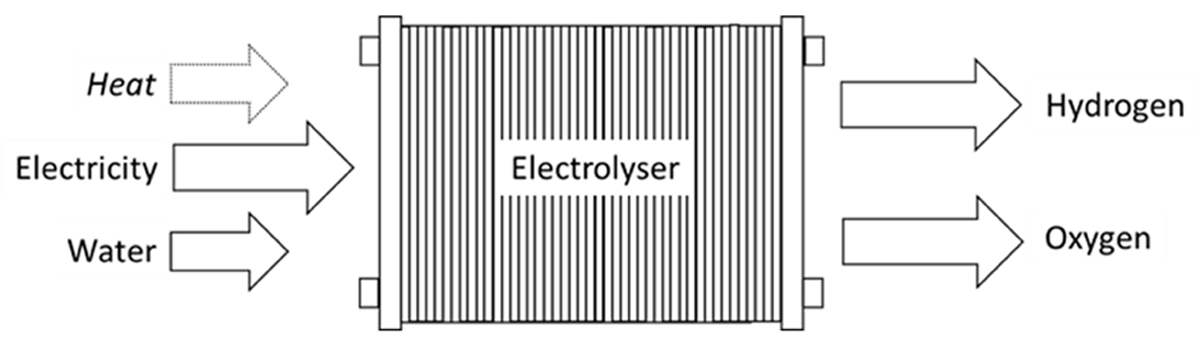
Figure 1
Electrolysis process.
Table 1
Results from the survey on electrolyzer safety distances.
| PARTICIPANT | PARTICIPANT A | PARTICIPANT B | PARTICIPANT C | PARTICIPANT D | PARTICIPANT E |
|---|---|---|---|---|---|
| Country | France | Global | EU, Australia, Japan | Sweden | Global |
| Regulation | ICPE 4715/1416 (ICPE 2024) | No standards followed | BCGA GN 41 ‘Separation Distances in the Gas Industry’ (BCGA 2020) | Suggested replacement for MSBFS 2020:1. (MSB 2020) | No standards followed |
| Methodology for Safety Distances | Consequence based at feasibility stage Risk based at detailed design stage | Consequence based at feasibility stage Risk based at detailed design stage | Follow BCGA separation distances (BCGA 2020) | Follow MSBFS 2020:1 (MSB 2020) approach which is consequence based. Risk based options exist. | Consequence and risk based approach |
| Leak Scenarios | Feasibility: Full bore (external safety distance)10% diameter leak (internal safety distance) Detailed design: Same approach but further refinements | 50 mm leak for consequence analysisSmall/Medium/Large/FBR leak for risk based | Prescribed safety distances from BCGA 41 (BCGA 2020) followed | 3% leak – asset damage10% leak – few fatalities100% leak (smaller dimensions) – many fatalities | Small leak (% of pipe diameter depending on country specific RCS)/medium/large leaks for risk based analysis |
| Harm Criteria | French Regulations criteria (140 mbar and 5 kW/m2 for lethal effect) orCompany specific harm criteria based on NFPA 2020People: 4.7 kW/m2 & 50 mbarBuildings: 25 kW/m2 & 140 mbarEquipment: 25–40 kW/m2 & 200 mbar | People: 5 kW/m2 & 140 mbarBuildings: 70–140 mbarEquipment: 37.5 kW/m2 & 200 mbar Risk Based:10–4/yr or 10–5/yr LSIR contour inside fenceSocietal Risk: PLL, FN-curve at specific location | People: 70 mbar & Thermal Effects from Table 3 from EIGA Doc 211/17 (EIGA 2024)Equipment: 35 kW/m2 | People: 309°C for individuals, 115°C for areas with dense groups of peopleBuildings: Flame impingementEquipment: 10–30 kW/m2 depending on type Overpressure (people/building): 50 mbar H2-concentration (human/opening): 8% | French regulations: Thermal radiation: 3 kW/m2, 5 kW/m2, 8 kW/m2 Overpressure:20 mbarg, 50 mbarg, 140 mbarg, 200 mbarg: |
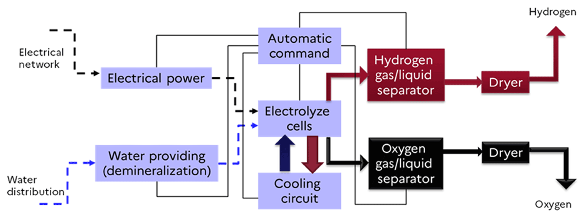
Figure 2
Schematic view of the functional description of an electrolyzer.
Table 2
Identification of the main phenomena and their impact on the definition of safety distances.
| THREATS | TOP EVENT | LIFE SAFETY CONSEQUENCES | CONSIDER FOR SAFETY DISTANCE? | RATIONALE |
|---|---|---|---|---|
| Electrical short circuit | Exposure to electrical equipment | Electrocution leading to injury or fatality | No | The person should be in direct contact with the corresponding equipment |
| Overpressure | In-equipment mixing of H2 and O2 | Jet fire, flash fire or explosion leading to injuries/fatalities | Yes | Depending on the explosive volume, and on the mitigation/prevention barriers the risk can be high |
| Component leaks/rupture leading to chemical exposure | Loss of containment of electrolyte | Chemical effect on people, local injury | No | Local impact compared to the scenario including ‘In-equipment mixing of H2 and O2’ |
| Component leaks | Loss of containment of hydrogen | Small leaks leading to potential flash fire | No | Small leaks during normal operations typically managed by hazardous area classification |
| Material damage leading to leakage in electrolyzer cell | In-equipment mixing of H2 and O2 | Jet fire, flash fire or explosion | Not directly, it a potential cause of a larger event | The potential explosive volume is low, however it has a potential to escalate to a more severe event. Needs to be carefully evaluated by the risk assessment |
| Overpressure, loss of containment | Loss of containment of hydrogen | Jet fire, flash fire or explosion | Yes | The potential consequences depend on the pressure and the inventory |
| Oxygen leak leading to fire | Loss of containment of oxygen | Fire due to presence of oxygen and high voltage equipment | No | Depending on the mitigation/prevention barriers the risk can be high, it can be managed via fire proved walls or limiting velocities |
| Degradation/Rupture of membrane | In-equipment mixing of H2 and O2 | Jet fire, flash fire or explosion leading to injuries/fatalities | Yes | Depending on the explosive mass, and on the mitigation/prevention barriers the risk can be high |
| Crossover of hydrogen into oxygen or vice versa | In-equipment mixing of H2 and O2 | Jet fire, flash fire or explosion leading to injuries/fatalities | Yes | Depending on the explosive mass, and on the mitigation/prevention barriers the risk can be high |
Table 3
Inputs for separations distances depending on the leak scenario.
| LEAK SCENARIO | INPUTS FOR SEPARATION DISTANCE | BASIS |
|---|---|---|
| Overpressure | Pressure: the design pressure of the system Hole Size: the reference hole size depends on local regulations, see for instance NFPA 2 (2023), PGS35 (Büthker et al. 2015), INERIS (2023) Temperature: between 5°C and 20°C | Basis for assumptions: for modeling use the events listed in Table 1 Harm criteria thresholds : according to local regulations and best practices The scientific research is ongoing on the topic of the hole size |
| Corrosion or other degradation reasons leading to leakage in cell | Pressure: the design pressure of the system Hole Size: the reference hole size depends on local regulations, see for instance NFPA 2 (2023), PGS35 (Büthker et al. 2015), INERIS (2023) Temperature : between 5°C and 20°C | Basis for assumptions: for modeling use the events listed in Table 1 Harm criteria thresholds : according to local regulations and best practices |
| Crossover of hydrogen into oxygen or vice versa | Pressure: the design pressure of the system up to 30barg The homogeneous mixture with various concentrations on both lean and rich sides could be potentially considered as a simplified approach, temperature is of 75°C, the full volume of a separator can be considered | The scientific research is ongoing on the topic |
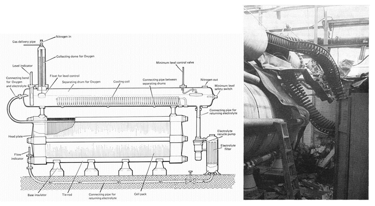
Figure 3
Laporte accident: drawing of the stack with the above oxygen separating drum (left) and a photograph of those components after the explosion (right) (HSE 1976).
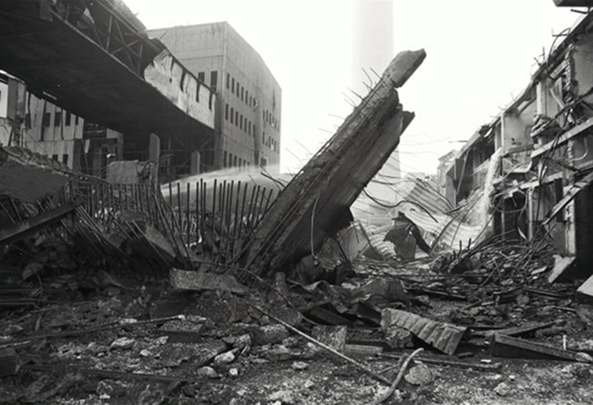
Figure 4
Blast of two large high-pressure storage cylinders destroying the Castle Peak power station electrolyzer site in 1992; Photo: SCMP.
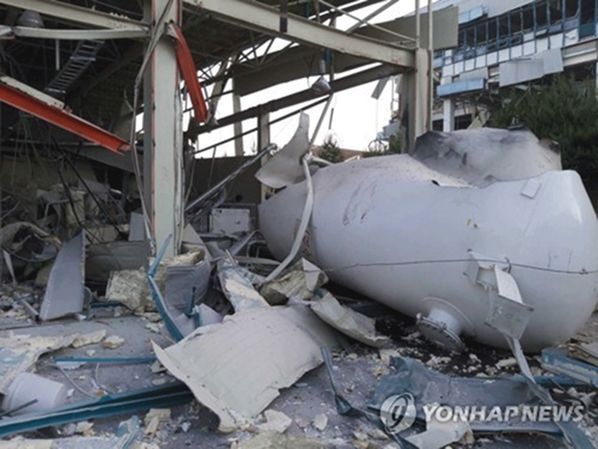
Figure 5
Blasted hydrogen storage cylinder at Gangneung accident, May 2019; Photo: YONHAPNEWS.