
1. Introduction
Hydrogen generation by electrolysis is important, as it both enables the storage of electrical energy in chemical form (i.e., as hydrogen) and enables the decarbonization of hydrogen production under specific circumstances (for instance, where renewable/low carbon sources of electrical energy are used as the supply to the electrolyzer).
This paper provides a general overview of electrolyzer processes and technologies, electrolyzer hazard identification, leak scenarios, safety distances, risk mitigation, existing regulations, codes, and standards (RCS), industry lessons learned, and recommendations. The work presented herein is a collaboration among industry experts participating in the IEA TCP H2 Task 43 (IEA TCP H2 2022) working group on safety distances and includes current state-of-the-art knowledge and best practices. The goal of this publication is to create a reference document giving minimal requirements and recommendations for hydrogen electrolyzer safety distances, which can be potentially used by electrolyzer manufacturers, operators, and regulatory bodies.
The publication explores the types of safety distances typically encountered in RCS, the types of more specific hazards encountered in electrolyzer technologies, and potential measures that can be taken to mitigate these hazards.
The paper consists of 8 main sections. The second section of the paper provides an overview of PEM and alkaline electrolyzer technology. Section 3 presents the current state of the art on RCS. Section 4 presents hazard identification. Section 5 provides a basis for the safety distance methodology for preventing corresponding worst-case scenarios, whereas Section 6 suggests associated prevention and mitigation barriers. Section 7 highlights the lessons learned from previous incidents. Finally, Section 8 provides conclusions and next steps.
2. Electrolyzer Technologies
2.1 General electrolysis
In the electrolysis process, water is decomposed into hydrogen and oxygen ions using electricity (and sometimes heat) to drive this nonspontaneous chemical reaction (Figure 1). This method of producing hydrogen is carbon-free when renewables are used or low-carbon when nuclear sources are used to generate the electricity for the process. Electrolysis utilizes three main components: an electrolyte, electrodes, and an external power source. A partition (e.g., an ion-exchange membrane) keeps the products from diffusing to the vicinity of the opposite electrode.
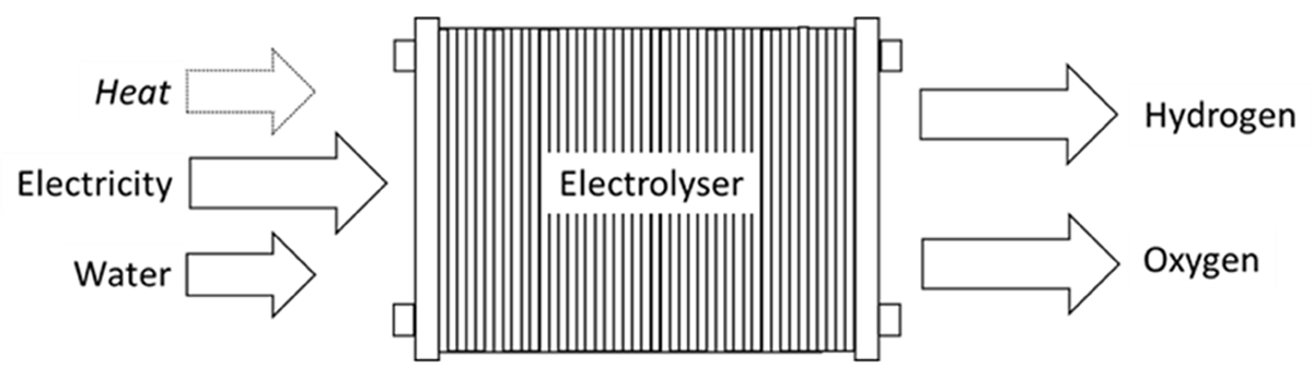
Figure 1
Electrolysis process.
Electrochemical reactions take place on the surface of catalytically coated electrodes of an electrolyzer and the transport of electrical charge between the electrodes occurs via ions supplied by the electrolyte. The electrodes are piled up to form the electrolyzer stack. The inner electrodes then act as bipolar plates connecting the end electrodes in series. In older designs, the electrodes of the stack were connected in parallel. Modern stacks require high direct voltage (calculated as the number of bipolar plates × 2 V), and a unipolar design operates at approximately 2 V direct current, implying relatively high electrical losses.
The following types of electrolyzers are referenced, depending on the electrolyte, which can be either a liquid or a solid and may be caustic or acidic.
Low-temperature electrolyzers:
Alkaline electrolyzer (AEC): liquid KOH aqueous solution (20–30%) as electrolyte with an operating temperature of 70–80°C and a Technology Readiness Level (TRL) of 9. This has the largest number of installed systems and is still the lowest cost for large-scale (≥1 MW) installations.
Alkaline membrane electrolyzer (AEMEC): solid plastic OH-ion conduction membrane as electrolyte with an operating temperature of ~80°C and a low TRL
Polymer electrolyte membrane electrolyzer (PEMEC): a solid plastic proton conduction membrane as electrolyte, with an operating temperature of ~80°C and TRL of 9
High-temperature electrolyzers:
Proton managing solid oxide electrolyzer (PCSOEC): ceramic proton conduction membrane as electrolyte with an operating temperature of ~500°C and a low TRL
Solid oxide electrolyzer (SOEC): negative oxygen ion conduction ceramics as electrolyte with an operating temperature of >800°C and a TRL of 7–8
The two more mature and prevalent types of electrolyzers are PEM and alkaline. These are discussed in more detail below.
2.2 Proton exchange membrane (PEM) electrolyzers
In a proton exchange membrane (PEM) electrolyzer, water splits into hydrogen and oxygen via an electrochemical reaction in the system (hydrogen at the cathode and oxygen at the anode). In these types of electrolyzers, water is fed to the anode side, and it is divided into oxygen, protons, and electrons. PEM electrolyzers use a proton conductive membrane polymer. Protons and electrons recombine to produce hydrogen. In industrial electrolyzers, the multiple electrolyte cells (in which the electrolysis reaction takes place) are arranged in series. The products from the electrolyzers are hydrogen and water in the cathode and oxygen and water in the anode. The operating temperature, pressure, and electrical current densities depend on the design of the PEM electrolyzers. However, it should be noted that there are PEM electrolyzers working at equal pressure on both the cathode and anode, while other PEM designs can operate with a differential pressure between the cathode and anode.
For the operation of the electrolyzer, separation of oxygen/water, water treatment, hydrogen/water separation, and hydrogen treatment (removal of oxygen traces and residual water) are required. These sections of the process are known as balance of plant. For electrolyzer systems in which oxygen is a product, additional treatment of the oxygen may be required. However, in several electrolyzer designs, the oxygen is a byproduct, and it is safely vented to the atmosphere. Electrolyzers shall follow the oxygen venting requirements included in ISO 22734-1 (under review at the submission date of the paper, anticipated publication date is 2025).
2.3 Alkaline electrolyzers
The alkaline electrolyzer, similar to the PEM system, consists of two electrodes: the anode (positive electrode) and the cathode (negative electrode). These electrodes are usually made from materials that are resistant to corrosion and can efficiently catalyze the electrochemical reactions, such as nickel or nickel alloys. Alkaline electrolyzers use an alkaline solution, typically potassium hydroxide (KOH) or sodium hydroxide (NaOH), as the electrolyte. This alkaline environment facilitates the movement of hydroxide ions (OH–) between the electrodes. Unlike proton exchange membrane (PEM) electrolyzers, alkaline electrolyzers do not use a solid polymer membrane. Instead, the alkaline solution acts as the medium for ion transport.
Alkaline electrolyzers are generally less expensive to manufacture compared to PEM electrolyzers, primarily due to the use of abundant and less costly materials. Alkaline electrolyzer technology represents a mature and reliable method for hydrogen production, particularly suited for large-scale applications. They have a long operational life and can operate effectively under a wide range of conditions. However, alkaline electrolyzers typically have a lower power density compared to PEM electrolyzers, which can limit their performance in applications requiring rapid response times. They may have longer start-up times and less flexibility in operation compared to other electrolyzer technologies. Last but not least, the alkaline environment can lead to the corrosion of certain materials, necessitating careful selection of components.
The electrolyte is delivered to both sides of the electrolyzer stack. Once it exits the stack, the alkaline solution must be separated from the generated gases. This separation occurs in gas-water separators, which are typically positioned above the stack. The water phase is extracted from the bottom, while the gas phase is collected from the top. The electrolyte solution is then returned to the stack. Additionally, the water column in the separator acts as a buffer storage to accommodate fluctuations in load requirements. This entire process system is commonly known as the Balance of Plant (BoP).
3. Safety Distance
3.1 Definition
A safety distance (otherwise known as a separation distance) is the distance to an acceptable risk level or the minimum risk-informed separation between a hazard source and an object (human, equipment, or environment) that will mitigate the effect of a likely foreseeable incident and prevent a minor incident from escalating into a larger incident (considering all mitigation and safety measures implemented) (ISO 2020a).
In various regulations and industrial practices, the term “safety distance” often includes many types of distances and can mean different things depending on the document in question. To help understand what safety distances are intended to do (which, in turn, helps define the methodology for establishing them), ISO 19880-1:2020 (ISO 2020a) provides guidance, making a distinction between safety distances designed to protect against different hazards, such as protection distances, clearance distances, installation layout distances, distances to external risk sources (external risk zone), and distances within which restrictions apply (restriction distances).
These safety distances are not intended to provide complete protection against catastrophic events. Protection against such major accidental events is fundamentally provided by a combination of multiple barriers (including but not limited to the safety distance) or through an emergency response plan.
For standard equipment and events, safety distances can be prescribed by national regulations and/or may be determined through quantitative risk assessment of a generic design. For any given system, one may also conduct a quantitative risk assessment (QRA), which can be used to understand the risks and the effects of station-specific mitigations; the result of the analysis may result in a recalculation of the safety distance to result in system-specific safety distances. If the safety distance is too large, additional mitigation or prevention measures should be considered, and the safety distances may be recalculated using a quantitative analysis.
The benefit of conducting quantitative analysis is that it generates safety distances that are specific to the system that is analyzed and can be used to demonstrate that the system does not pose unacceptable risk to specific targets, taking into account the design and mitigation features of the actual installation. Acceptable quantitative techniques include QRA and consequence modelling. The analysis uses a combination of information and data regarding hydrogen facilities design and operation, validated physical models, and probabilistic models that meet the criteria discussed in the remainder of this clause.
This paper will focus on safety distances between electrolyzer equipment and facility boundaries.
EIGA document 75/21 (EIGA 2021) (Methodology for determination of safety and separation distances) describes the basic principles to calculate appropriate safety and separation distances for the industrial gases industry. This methodology can be explained in four steps:
Identify the hazard sources and events, taking into account the likelihood
Calculate the effects on neighboring objects and population, taking into account mitigating factors
Determine the safe distance to each object or population to meet the minimum hazard criteria
Consider additional prevention or mitigating factors and recalculate safe distance
It is important to highlight that the safety and separation distances are not intended to provide protection against catastrophic events or major releases; these should be addressed by other means to reduce the frequency and/or consequences to an acceptable level.
3.1 Existing regulations, codes, and standards (RCS)
There are a number of relevant safety aspects in regulations, codes, and standards applicable to electrolyzers. The most important and widely used RCS are discussed below; however, it should be noted that this list is not exhaustive.
The most relevant standard to the majority of electrolyzers is ISO 22734. The latest version was published in 2019, with the title ‘Hydrogen generators using water electrolysis — Industrial, commercial, and residential applications’ (ISO 2019). This standard was developed by ISO TC 197, originally as ISO 22734-1, for industrial and commercial applications, and ISO 22734-2 for residential applications. A revision was published in 2019 (ISO 2019), combining requirements from ISO 22734-1 and ISO 22734-2, for industrial and commercial applications and residential applications (previously separated). This enabled consistency between documents and brought requirements up to date with learnings from manufacturer experience and from other standards (e.g., ISO 19880-1 (ISO 2020a)).
The standard covers the following areas:
Operating conditions: specifications and gas quality
Risk management
Mechanical equipment and components
Electrical equipment, including explosion protection
Control system, including safety integrated functions (SIF)
Electrolyte/membranes
Test methods: type (qualification) tests and routine tests
Marking and labeling
Documentation
In May 2021, a new project was registered in ISO/TC 197 to further develop ISO 22734-1 on the safety topic (ISO 2025). At the time, the areas requested for potential further development were as follows:
New requirements for dynamic operation: safety requirements, including tests if needed, and tests for performance when used for dynamic operation to be covered in new document
Oxygen venting
Ensuring requirements appropriate to size of electrolyzer (scale up)
Installation into buildings/parallel with other enclosed systems (e.g., HRS)
Safety integrated systems becoming more important
Power electronics/connection to the grid (unless this merits a separate document)
Safety distances
Others…
During the current revision, it is unlikely that the areas initially hoped to be addressed will be able to be addressed, partially due to a large amount of development of the existing content and improvements to requirements based on experiences of using ISO 22734:2019 (ISO 2019). This also includes safety distances.
Some of the most important directives and regulations in the EU:
The Pressure Equipment Directive, European Directive 2014/68/EU (PED) (Directive 2014/68/EU)
The Machinery Directive, European Directive 2006/42/EC (Directive 2006/42/EC)
The Low Voltage Directive, European Directive 2014/35/EU (Directive 2014/35/EU)
The Electromagnetic Compatibility Directive, European Directive 2014/30/EU (Directive 2014/30/EU)
Elements of the “ATEX Equipment Directive”, European Directive 2014/34/EU (Directive 2014/34/EU), even if most electrolyzers are not designed to operate in hazardous areas and therefore are unlikely to be ‘ATEX rated’; however, control of ignition sources is usually required in the potentially explosive atmospheres within or surrounding an electrolyzer.
Others, but not limited to:
IEC 60079-10-1: Classification of explosive gas atmospheres (IEC 2020), useful for zoning in electrolyzer installations
EU:
Seveso (Directive 2012/18/EU (Directive 2012/18/EU) on the control of major-accident hazards involving dangerous substances)
EIGA Doc 13/20, Oxygen piping systems (EIGA 2020)
In the North America:
NFPA 2 : Hydrogen Technologies Code (NFPA2 2023), which addresses hydrogen storage, handling, and use, including electrolyzers
NFPA 69: Standard on Explosion Prevention Systems (NFPA69 2024)
NFPA 70: National Electrical Code (NFPA70 2023), governing the safe installation of electrical wiring and equipment
NFPA 496: Standard for purged and pressurized enclosures (NFPA496 2024)
ASME B31.12: Hydrogen piping and pipelines (ASME 2008)
ASME Boiler and Pressure Vessel Code: Standards for pressure vessels, relevant to electrolyzer system components like separators and heat exchangers (ASME 2023)
CGA G-5.4 (for hydrogen piping systems) (CGA 2019)
CGA G-4.1 (oxygen handling) cover related system components (CGA 2018)
CGA G-5.5: Hydrogen vent system guidelines (CGA 2021)
ASTM G93: Cleanliness standards for materials used in oxygen-enriched environments (ASTM 2019), often applicable due to oxygen as a by-product of electrolysis
Among these documents, only NFPA 2 (2023) gives an insight into the safety distances; however, the current version (published in 2023) is not fully adapted for the electrolyzers and does not make a difference in technology.
3.2 Survey results
A survey was sent out to over 30 different participants of IEA TCP Task 43 (IEA TCP H2 2022) in 2020–2023 to obtain feedback on how safety distances were determined for electrolyzers in different regions. An excerpt of the results is shown in Table 1.
Table 1
Results from the survey on electrolyzer safety distances.
| PARTICIPANT | PARTICIPANT A | PARTICIPANT B | PARTICIPANT C | PARTICIPANT D | PARTICIPANT E |
|---|---|---|---|---|---|
| Country | France | Global | EU, Australia, Japan | Sweden | Global |
| Regulation | ICPE 4715/1416 (ICPE 2024) | No standards followed | BCGA GN 41 ‘Separation Distances in the Gas Industry’ (BCGA 2020) | Suggested replacement for MSBFS 2020:1. (MSB 2020) | No standards followed |
| Methodology for Safety Distances | Consequence based at feasibility stage Risk based at detailed design stage | Consequence based at feasibility stage Risk based at detailed design stage | Follow BCGA separation distances (BCGA 2020) | Follow MSBFS 2020:1 (MSB 2020) approach which is consequence based. Risk based options exist. | Consequence and risk based approach |
| Leak Scenarios | Feasibility: Full bore (external safety distance)10% diameter leak (internal safety distance) Detailed design: Same approach but further refinements | 50 mm leak for consequence analysisSmall/Medium/Large/FBR leak for risk based | Prescribed safety distances from BCGA 41 (BCGA 2020) followed | 3% leak – asset damage10% leak – few fatalities100% leak (smaller dimensions) – many fatalities | Small leak (% of pipe diameter depending on country specific RCS)/medium/large leaks for risk based analysis |
| Harm Criteria | French Regulations criteria (140 mbar and 5 kW/m2 for lethal effect) orCompany specific harm criteria based on NFPA 2020People: 4.7 kW/m2 & 50 mbarBuildings: 25 kW/m2 & 140 mbarEquipment: 25–40 kW/m2 & 200 mbar | People: 5 kW/m2 & 140 mbarBuildings: 70–140 mbarEquipment: 37.5 kW/m2 & 200 mbar Risk Based:10–4/yr or 10–5/yr LSIR contour inside fenceSocietal Risk: PLL, FN-curve at specific location | People: 70 mbar & Thermal Effects from Table 3 from EIGA Doc 211/17 (EIGA 2024)Equipment: 35 kW/m2 | People: 309°C for individuals, 115°C for areas with dense groups of peopleBuildings: Flame impingementEquipment: 10–30 kW/m2 depending on type Overpressure (people/building): 50 mbar H2-concentration (human/opening): 8% | French regulations: Thermal radiation: 3 kW/m2, 5 kW/m2, 8 kW/m2 Overpressure:20 mbarg, 50 mbarg, 140 mbarg, 200 mbarg: |
In general, the comparison demonstrated a large variety of the responses. As expected, different geographies refer to different regulations, and several respondents highlighted the fact that there is no mandatory worldwide regulation or standards for electrolyzers. This highlights the potential opportunities for harmonization of leak scenarios and harm criteria to have a consistent methodology to determine safety distances.
The survey results demonstrate that there is no common approach for the definition of the most impactful scenarios leading to a loss of containment; see also the publication in reference (Vyazmina et al. 2023). For instance, in this publication (Vyazmina et al. 2023), it is detailed how several participants considered the potential explosion of the separator due to the crossover of oxygen to hydrogen or mixing of hydrogen and oxygen (through H2 and O2 separator’s balancing line) and suggested barriers to reduce the risk, whereas other contributors did not consider this scenario in their risk assessments. Several participants of IEA TCP H2 Task 43 (IEA TCP H2 2022) also highlighted a gap in the methodology for the definition of the separation distances between hydrogen and oxygen atmospheric vents at an electrolyzer.
In addition, the results indicate that there was a difference in the leak scenarios considered. A range of hole sizes was used, with each participant applying a different approach for the leak size to be used to determine the safety distance. A wide range of harm criteria was reported by the participants. For instance, in several geographies the radiation heat flux from the flame is mainly considered, whereas in another geography the temperature of the products (convective heat flux) was taken into account. Furthermore, some participants considered overpressure threshold limits for people based on an explosion, while others did not. The recommendations on the harm criteria threshold and the harmonization of the approach are also of high importance.
Harm criteria is a very large topic and is not considered in the current paper. The main focus is to give the list of scenarios to be used as the basis for separation distances for electrolyzers and why.
4. Hazard Identification
Hazard identification always requires a functional description of the system first. A generic overview of this function description for an electrolyzer is presented in Figure 2.
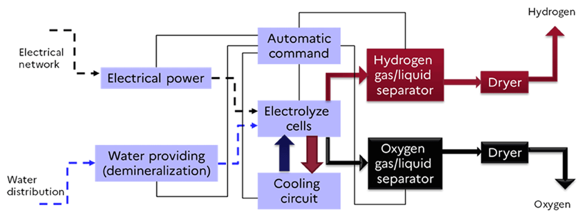
Figure 2
Schematic view of the functional description of an electrolyzer.
Electrolyzers are subject to several hazards associated with flammable gases in close vicinity with their reaction partners (oxygen or chlorine), chemically aggressive media (oxygen and the acidic or caustic electrolytes), and electricity. Failures of the electrolyzer system, its components, and processes lead to exposure to these hazards. Leaks and ruptures can cause the release of flammable hydrogen. The presence of relatively high voltages provides a steady source of ignition. Leaks and ruptures can be accelerated by the presence of chemically aggressive media. Impurities might lead to operational deviations or deterioration and even initiate reactions on catalytic surfaces. Higher pressures and temperatures increase the corresponding hazards and promote material degradation in combination with electrochemical aggression with oxygen, chlorine, and hydrogen, respectively.
In addition, hazard conditions are steadily present in electrolyzers, that means that the degradation of membrane materials is inevitable (Choi et al. 2020).
The key elements of the technical requirements for electrolyzer performance are: ramp up/ramp down time, power consumption stability, duration of operation at a defined power level, and operation between defined minimum and maximum power. These will lead to the following degradation aspects:
Operation aspects of dynamic operation causing increased degradation:
Long-time OCV (open-circuit voltage), frequent shutdowns
Long-time high currents
Temperature variation induced defects
Mechanical stress (e.g., on membrane) due to fast pressure variations
High temperature
Water impurities
The most critical aspects of the electrolyzer are the BoP supporting the operation of the electrolyzer stack. As the electrolyzer stack itself provides only small, free volumes and huge surfaces, the stack itself might be considered less critical with regard to explosion hazards. However, as indicated before, the stacks provide huge membrane and electrode surfaces, which imply a huge potential for permeation or small leakage via imperfect seals, small fractures, or holes. This may lead to small continuous releases from the stack or to a crossover within the stack, leading to a mixing of the product gases.
However, more critical regarding explosion hazards are components offering larger free volumes, like phase separators, cleaning devices, and storage vessels. These types of equipment offer the potential for hydrogen or oxygen accumulation or mixing, leading to potential fires and explosions. Furthermore, electrolyzers are usually installed in a building or in a container to protect them from the varied environmental conditions. The potential leakage from the electrolyzer system into confined or enclosed areas can lead to hydrogen or oxygen accumulations, leading to potential fires and explosions. The risk scales with the amount or inventory of the involved chemicals.
A more extensive description of the key hazards, failure modes, and failure mechanisms for PEM electrolyzers can be found in Wismer et al. (2024) and Groth et al. (2024). Recent QRA modeling efforts by the University of Maryland for EPRI have provided detailed insight into a PEM electrolyzer configuration and provide risk-informed insight into which electrolyzer safety measures and risk mitigation measures should be prioritized (Groth et al. 2024; Al-Douri et al. 2025).
In the current work, the following list of possible hazards, failure modes, and mechanisms (applicable to both alkaline and PEM electrolyzers unless specifically stated below) are considered; see, for example, (ISO 2025; Choi et al. 2020; Wismer et al. 2024; Groth et al. 2024; Al-Douri et al. 2025; ISPT 2023):
High voltage, electrical short circuits or discharges, electrocution
Corrosion caused by acidic/caustic electrolyte (more applicable to alkaline than PEM) and electrochemistry
Leakage of electrolyte (more applicable to alkaline than PEM)
Freezing of the cooling water in the stack
Fracture of a pressurized pipe or compartment
Failure (rupture) of a vessel or component causes the pressure hazard
Excessive thermal stresses causing material degradation, for example, a long-term overload operation: overheating, hotspots
Hydrogen leakage from the stack can create a flammable gas that, when released into the air, forms a potentially explosing atmosphere
Potential accumulation and buildup of hydrogen
Oxygen leaks can also potentially increase the propensity for combustion or otherwise non-combustible materials especially in the presence of the high-voltage sources
Degradation of membrane or break of membrane due to, for instance, pressure difference between hydrogen and oxygen compartment
Break of membrane in bipolar plates
Crossover of oxygen into hydrogen and vice versa
Accumulation of explosive hydrogen and oxygen mixtures in the phase separator or in the gas storage or other internal pressure systems
5. Scenarios considered for safety distances
Scenarios considered in this section have also been elaborated upon in Section 7.
5.1 Identification of main phenomena
The following scenarios from the HAZID (HAZard Identification), presented, for instance, in (ISPT 2023) are listed in Table 2.
Table 2
Identification of the main phenomena and their impact on the definition of safety distances.
| THREATS | TOP EVENT | LIFE SAFETY CONSEQUENCES | CONSIDER FOR SAFETY DISTANCE? | RATIONALE |
|---|---|---|---|---|
| Electrical short circuit | Exposure to electrical equipment | Electrocution leading to injury or fatality | No | The person should be in direct contact with the corresponding equipment |
| Overpressure | In-equipment mixing of H2 and O2 | Jet fire, flash fire or explosion leading to injuries/fatalities | Yes | Depending on the explosive volume, and on the mitigation/prevention barriers the risk can be high |
| Component leaks/rupture leading to chemical exposure | Loss of containment of electrolyte | Chemical effect on people, local injury | No | Local impact compared to the scenario including ‘In-equipment mixing of H2 and O2’ |
| Component leaks | Loss of containment of hydrogen | Small leaks leading to potential flash fire | No | Small leaks during normal operations typically managed by hazardous area classification |
| Material damage leading to leakage in electrolyzer cell | In-equipment mixing of H2 and O2 | Jet fire, flash fire or explosion | Not directly, it a potential cause of a larger event | The potential explosive volume is low, however it has a potential to escalate to a more severe event. Needs to be carefully evaluated by the risk assessment |
| Overpressure, loss of containment | Loss of containment of hydrogen | Jet fire, flash fire or explosion | Yes | The potential consequences depend on the pressure and the inventory |
| Oxygen leak leading to fire | Loss of containment of oxygen | Fire due to presence of oxygen and high voltage equipment | No | Depending on the mitigation/prevention barriers the risk can be high, it can be managed via fire proved walls or limiting velocities |
| Degradation/Rupture of membrane | In-equipment mixing of H2 and O2 | Jet fire, flash fire or explosion leading to injuries/fatalities | Yes | Depending on the explosive mass, and on the mitigation/prevention barriers the risk can be high |
| Crossover of hydrogen into oxygen or vice versa | In-equipment mixing of H2 and O2 | Jet fire, flash fire or explosion leading to injuries/fatalities | Yes | Depending on the explosive mass, and on the mitigation/prevention barriers the risk can be high |
Additional scenarios for hydrogen and oxygen venting, not considered in the current paper but that shall be taken into account for the layout, are:
Fire from hydrogen vents: For the determination of safety distances, ignition of hydrogen being vented from depressurization lines or pressure relief valves (PRVs) should be considered. This scenario should be addressed by a safe design of hydrogen venting systems (see G-5.5 Standard for Hydrogen Vent Systems (CGA 2021) and (EIGA 2024)).
For large-scale hydrogen production plants, consideration of flares should be investigated; the flare height and location shall be selected to meet thermal radiation criteria.
Oxygen-enriched atmospheres (dependent on design): If oxygen is released to the atmosphere, an enriched atmosphere of oxygen around the vent will be obtained and should be considered as a potential source for oxygen fires. This scenario should be addressed by a safe design of oxygen venting systems (EIGA doc 154 (EIGA 2016) and CGA P8.7-16 (CGA 2016) addressing safe location of oxygen vents).
The co-location of hydrogen and oxygen vents is also out of scope of this paper, and it should be considered at the layout stage of the project.
5.2 Loss of containment (leaks) of hydrogen and potential accumulation
The potential overpressure of different equipment, such as piping, phase separates, valves, etc., can lead to a loss of containment and release of hydrogen to the atmosphere. This can be due to hydrogen embrittlement of compounds. The selection of materials suitable for H2 service and operating conditions is therefore crucial (e.g., ISO 16573 (ISO 2020b; ISO 2022)). There are many other causes for the loss of containment, e.g., thermal stress, vibration, mechanical impacts, fatigue failures, metallurgical failures (e.g., manufacturing defects, cracks, material defects), corrosion, connection failures, operating errors (e.g., assembly, maintenance), accidental loads, etc.
Usually, the equipment is protected by relief valves, pressure sensors, and hydrogen sensors, so the catastrophic full-bore rupture scenario has a very low probability. Hence, for the scenario defining safety distances, a limited hole size scenario (typically 10% of the largest pipe diameter) can be selected as the reference scenario (also referred to as the credible foreseeable scenario).
Moreover, larger diameter leak scenarios are usually managed by conventional mitigation and protection barriers such as fire and gas detection, isolation, depressurization, purging, ventilation, control of ignition sources, fire and explosion protection, etc.
Hydrogen leaks can generate flammable clouds that, in the presence of an ignition source, could lead to a fire or explosion. In enclosed conditions, leaks from hydrogen handling elements:
could produce a jet fire from a pressurized release in case of immediate ignition.
could accumulate and produce an internal explosion in case of a delayed ignition.
The absence of dead zones in enclosures, ventilation, detection, isolation, and depressurization capacities will help avoid any significant accumulation. In several scenarios, the necessary ventilation flow rate required to dilute the leak below the lower flammability limit becomes prohibitive (e.g., for leaks larger than a few mm). Hence, significant H2 accumulation can occur, forming a dangerous atmosphere before the isolation and effective depressurization of the system are activated. In such a situation, explosion vent panels can be considered to prevent the structural failure of the building and deal with the residual explosion risk. However, for concentrations of hydrogen close to or higher than 20%, the required vent surface usually becomes too large to reduce the consequences, and the risk of detonation, especially in highly obstructed areas, becomes possible.
In addition, leaks from hydrogen handling elements from the electrolyzer that are outdoors, depending on the leak size and operating conditions, could breach the hazardous area classification and result in an external flash fire or explosion (depending on conditions) in the presence of an ignition source.
The following variables should be considered when determining safety distances in loss of containment scenarios:
Capacity of the electrolyzer system: The determination of safety distances assumes leak scenarios that are not catastrophic (full rupture) but are well above the leaks considered for hazardous area classification. For example, NFPA 2 (2023) uses a leak diameter equivalent to 1% of the flow area of the system’s pipework. However, depending on the electrolyzer design, the flow rate obtained at such conditions is above the maximum generation of the electrolyzer. This should be considered for the assessment of the maximum leak to be considered for the assessment of safety distances. In the case of the presence of the flow restrictor (restriction orifice) within the pipe, the maximum flow rate downstream is defined by the diameter of this calibrated orifice. In the case of the presence of excess flow valves, the flow rate for the excess flow valve is characterised by the valve design (sufficient flow or force to overcome the power of the spring holding it open) (EHSP 2023).
Artificial ventilation: A lot of electrolyzer systems incorporate artificial ventilation sized to provide the necessary dilution to comply with hazardous area requirements. While the leak sizes for hazardous area classification are very small, the ventilation system is designed to provide dilution for such leaks that would result in concentrations below 1% vol H2 (Annex C of IEC 60079-10-1:2020 (IEC 2020) or clause 4.4.1.4 of ISO 22734:2019 (ISO 2019)).
5.3 Oxygen fire and leaks
In an oxygen system, oxygen is the oxidizer, whereas the piping or construction materials (including metals, non-metals, seals, and lubricants) play a fuel role. Common ignition sources in oxygen systems are particle impacts, compression heating, frictional heating, etc. The risk of fire escalates with higher concentrations, pressures, temperatures, and flow rates.
As mitigation prevention barriers, the following approaches are considered (EIGA 2020):
Lowering the oxygen pressure and temperature, where feasible
Using burn-resistant alloys in areas where ignition mechanisms are potentially present, including protective liners and weld overlays or coatings of burn-resistant alloys
Minimizing the intensity of ignition mechanisms could involve implementing oxygen service cleaning to decrease particle impact and enhance combustion, as well as eliminating adiabatic compression and other contributing factors
Ensure a release of O2 at a safe location (separated from H2 venting)
If compliance with the velocity curves limitation presented in EIGA (2020) cannot be ensured at the whole range of operational conditions and the application of burn-resistant alloys and coatings is not implemented, the protective barriers (firewalls) should be considered. The decision to place a component behind a protective barrier depends on various factors, including material selection, pressure, gas velocity, piping size, personnel exposure, and site location. The primary purpose of these barriers or screens is to mitigate the effects of any incidents when containment is not feasible, thereby providing additional safety for operators, maintenance staff, and the surrounding environment and equipment. (EIGA 2020) also gives recommendations for the design of these protective barriers.
Oxygen can be safely vented to the atmosphere, ideally in an outdoor location away from buildings and enclosed spaces. This site should ensure that personnel and sensitive equipment are not subjected to oxygen-enriched environments. Additionally, compressors and combustion-engine vehicles should not be used in areas with oxygen levels exceeding 23.5%. Venting should also be avoided directly beneath high-voltage overhead power lines and away from potentially hydrogen-enriched atmospheres.
The specific fire hazards associated with oxygen systems include:
Spontaneous combustion within the oxygen system, which can quickly escalate into a fire. While such fires typically extinguish within seconds, the release of a significant amount of oxygen can lead to an oxygen-enriched environment
Combustion in oxygen-enriched air/atmosphere, which can be managed using standard firefighting techniques once the oxygen supply has been halted
The most effective method for addressing fires fueled by oxygen is to isolate the oxygen supply. In oxygen-enriched situations, suitable firefighting agents include water, dry chemical powders, or carbon dioxide. The choice of agent should consider the type of fire (e.g., electrical fires).
Due to the prevention and mitigation measures applied to the potential of oxygen fires, hydrogen fires and explosions are often used as the bounding scenario for the determination of safety distances (see Table 2). The designer must define if the risk is high in comparison with other scenarios and define if it should be considered as part of the separation distance assessment.
5.4 Hydrogen/oxygen crossover
In electrolyzer systems, certain deviations from normal operation of the plant could lead to the hazardous accumulation of hydrogen/oxygen mixtures in the separators (O2/H2O or H2/H2O separator). These deviations could originate on the BoP or by aging or mechanical failure of the diaphragm or membrane (perforation, rupture, tearing, degradation). Some such categories of BoP deviations that could cause membrane damage and subsequent gaseous crossover are identified in Wismer et al. (2024):
Manufacturing or assembly defect in the electrolyzer cell
Electrochemical corrosion of the cell
Heterogeneous distribution of currents
Poor wetting
Failures of the water supply pump to operate and supply water to the electrolyzer, causing water starvation
Full or partial obstructions to the flow of water in the system due to freezing or plugging that prohibit water flow to the electrolyzer and cause water starvation
Leak or rupture of water containing components that lead to the electrolyzer or along the water recycle lines that cause water starvation of the electrolyzer
Poor water quality input to the electrolyzer
Improper cooling of the electrolyzer stack due to loss of chilled water and appearance of hot spots
Abnormal power input (high) causing a possible temperature increase
Increased hydrogen side pressure due to pressure signal failures or valve blockages
The formation of flammable atmospheres in the separators will depend on the operational pressure of the cathode and anode. Atmospheric alkaline technology operates around several mbars of the differential pressure, with a porous and weak diaphragm, where even a marginal imbalance could potentially lead to a significant gas flow through the diaphragm or even its mechanical failure. PEM technology is less sensitive to differential pressure, and often the membrane operates at a high positive differential pressure of 30 bar. The membrane is both liquid-tight and much more resistant. On the other hand, the membrane is, by design, particularly vulnerable to a negative differential pressure.
In systems working at differential pressure (e.g., higher pressure at the cathode in comparison to the anode), the flow of hydrogen would be driven by the differential pressure, and accumulation of hydrogen will happen in the O2/H2O separator. It is unlikely that oxygen flow to the H2 system could happen due to the abnormal conditions. Considering the use of renewable and clean energy sources as input to the electrolyzer and the possible variable current load, it is understood that there could be a change in differential pressure across the stack that could allow for the crossover of oxygen to the hydrogen side of the system. For systems that recycle water from the H2/H2O for use in the electrolyzer, there is the potential for hydrogen gas collection in the O2/H2O separator if a proper seal is not maintained on the H2/H2O separator.
The ignition of this hydrogen/oxygen mixture within an electrolyzer separator can result in an internal explosion, leading to a rupture due to overpressure, thermal effects such as a fireball, and the ejection of debris, gas, and/or liquid into the surrounding environment. The overpressure of the explosion is proportional to the initial pressure and could potentially reach several hundred bars in a pressurized system with a sufficiently rich mixture (Coudoro et al. 2023). If the flammable mixture is contained within the stack, the volume is limited, as most gases are dissolved in the electrolyte. Consequently, the primary outcomes are likely to be material damage to the stack and the expulsion of liquid containing a small amount of dissolved gas (such as KOH in an alkaline system).
The presence of a balancing line between the hydrogen and oxygen separators on alkaline technology also presents a risk of a massive transfer between separators. Pressurized electrolyzers are particularly vulnerable to this. On atmospheric electrolyzers, the differential pressure remains limited. A correctly sized hydraulic guard generally prevents this event.
The main causes of massive transfer of hydrogen or oxygen by the balancing line are:
A regulation failure
A closed, blocked, or blocked-open gas outlet
A variation in the incoming/outgoing electrolyte flow rates
A differential activation of pressure relief valves
Differential flow rates on the H2/O2 side during start-up/stoppage or emergency depressurization
Safety Instrumented Systems (designed according to the requirement of IEC 61511 (IEC 2024)) on differential pressure and level of the separators for alkaline electrolyzers equipped with a balancing line can prevent or significantly limit the consequences of such events.
For the determination of safety distances, the potential hazardous events will depend on the potential leak rate of hydrogen or oxygen and the stage of operation. For instance, a leak of hydrogen to the oxygen side during generation (unmitigated) could potentially reach higher concentrations at lower current densities, as there will be less oxygen production to dilute a potential loss of containment.
The following prevention and mitigation barriers can be used to reduce the risk of the crossover:
The oxygen and hydrogen sensors shall be installed to measure the concentration in gaseous crossover
Flow sensors and flood sensors to be installed to ensure the proper flow in the electrolyzer stack
Balancing the depressurization flow rates also involves installing restriction orifices on the hydrogen and oxygen sides
Temperature sensors to monitor the temperature of the stack outlet
Pressure sensors to ensure the proper pressure differential
Voltmeter, amperemeter, and cell voltage monitoring (CVM) to ensure the proper voltage and current power on the stack
Filter to be installed upstream of the stack to prevent the water contamination from debris and small particles
For specific systems that require deionized water, there should be resistivity sensors to ensure proper water quality input to the stack
Preventative measures to ensure limited corrosion of components, specifically for components using deionized water
Regular maintenance and inspection of the membrane
Special design of separators to limit the effects of potential explosion
PSV pressure safety valve
Note: The installation of PSVs on the separators for alkaline electrolyzers is often incompatible with the presence of a balancing line. The activation of PSV can generate a pressure differential and cause gas to pass from one separator to another. Protection against overpressure is then ensured by instrumented loops (differential pressure, differential level).
5.5 Separation distance inputs
The following assumptions can be made for the calculation of hazardous distances depending on leakage scenarios.
Table 3
Inputs for separations distances depending on the leak scenario.
| LEAK SCENARIO | INPUTS FOR SEPARATION DISTANCE | BASIS |
|---|---|---|
| Overpressure | Pressure: the design pressure of the system Hole Size: the reference hole size depends on local regulations, see for instance NFPA 2 (2023), PGS35 (Büthker et al. 2015), INERIS (2023) Temperature: between 5°C and 20°C | Basis for assumptions: for modeling use the events listed in Table 1 Harm criteria thresholds : according to local regulations and best practices The scientific research is ongoing on the topic of the hole size |
| Corrosion or other degradation reasons leading to leakage in cell | Pressure: the design pressure of the system Hole Size: the reference hole size depends on local regulations, see for instance NFPA 2 (2023), PGS35 (Büthker et al. 2015), INERIS (2023) Temperature : between 5°C and 20°C | Basis for assumptions: for modeling use the events listed in Table 1 Harm criteria thresholds : according to local regulations and best practices |
| Crossover of hydrogen into oxygen or vice versa | Pressure: the design pressure of the system up to 30barg The homogeneous mixture with various concentrations on both lean and rich sides could be potentially considered as a simplified approach, temperature is of 75°C, the full volume of a separator can be considered | The scientific research is ongoing on the topic |
6. Mitigation
In Section 5, a general description of the mitigations associated with each scenario considered for the determination of distances has been included. In this section, a detailed description of the worst-case scenarios related to electrolyzer for separation distance is developed, as those scenarios would potentially result in the longer distances. These scenarios are:
– explosion inside one of the two separators (i.e., H2/O2 mix)
– explosion inside container/building following a hydrogen release
To reduce separation distances related to separator explosion, many types of safety barriers might be considered to provide defense in depth:
Inherent safe design, operational conditions, design of separator, etc.
Mechanical integrity inspections, routine maintenance, and leak prevention efforts
Engineering controls preventing the likelihood of the hazardous event i.e., interlocks on level measurement with emergency protocol
The following prevention and mitigation measures can be used:
Pressure monitoring and pressure equilibrium control
Pressure equilibrium line between H2 and O2 phase separators for atmospheric pressure electrolyzer
PSV, per API 521 (API 2020), in the absence of the equilibrium line for alkaline electrolyzer
Temperature monitoring
Independent safety loops on process parameters (pressure, level, flow, temperature, load)
Monitoring of the concentration of O2 in H2 and H2 in O2 with SIL at least 2, to double the number of sensors or sampling points
Gas detection (associated with an alarm threshold at 10% LEL and a safety procedure activation at 25% LEL), automatic activation of isolation, depressurization and purging, and fire detection
Control/elimination of ignition sources
Smart design of the phase separator to avoid severe flame acceleration
Over-dimensioning for the static pressure load corresponding to 10% O2 on the hydrogen side (an expensive solution)
Prevention of flow blockages due to freezing and plugging in critical equipment, including process valves;
Increased interior volume for electrolyzer enclosures
Firewalls (if applicable)
To reduce the probability of the oxygen fire, the velocity limit on the oxygen side shall be followed as recommended in (EIGA 2020).
To reduce separation distances related to confined explosions, the efficiency and reliability of the gas detection and ventilation capacity might be taken into consideration.
Moreover, the following protection safety barriers could be implemented to reduce separation distances related to explosions inside electrolyzer container:
Pressure relief panel on the roof of the electrolyzer building/container to reduce overpressure effect distances
Blast walls for large-scale industrial use (not for containerized solutions) to protect assets and people from overpressure effects in case of hydrogen explosion from electrolyzer
Other active and passive barriers, as well as good practices for both alkaline and PEM electrolyzer systems, are described in (ISPT 2023).
7. Lessons Learned
In search of lessons learned from past accidents related to electrolysis processes, two hydrogen-specific databases were consulted: HIAD 2.0 and H2TOOLS (H2TOOLS 2025) in the preparations for the FCH 2 JU Workshop on Safety of Electrolysis on 18 November 2020 (Azkarate et al. 2020).
In the majority of cases (11 of 14 in HIAD 2.0-status 2020), accidents occurred in chlorine production by electrolysis, where hydrogen actually is a byproduct. A typical cause of fires and explosions in this alkaline chlorine electrolysis is the accidental creation and ignition of flammable gaseous mixtures (hydrogen-chlorine, hydrogen-air/oxygen) in the electrolyzer cells, in the hydrogen handling system, and at the flare. The management of the various chemical flows (gases, liquids) to and from the electrochemical cells, as well as phase separation, is a clear challenge in these plants, which are characterized by a limited level of automation. Due, in particular, to the needs of material recirculation, it can happen that a failure on an auxiliary system, such as a recirculation pump, can produce flammable mixtures back in the electrolytic cells. A short circuit in the cell can also be an initiating event. Often these events occurred during maintenance or repair work or after tripping of components (e.g., compressors, pumps). This last observation points at a more difficult identification of hazards during nonoperative circumstances with the involvement of contractors. For an overview of typical accidents related to chlorine production plants, see (Pennel 1963).
Fewer accidents in the databases affect electrolysis dedicated to hydrogen production. Their number is too small to deduce reliable statistics or general trends. However, a few lessons learned might be derived.
Two accidents occurred in a research laboratory. They could be studied in detail, shedding light on cell degradation phenomena of PEM electrolyzer cells. This is typically a two-step process involving firstly the local perforation of the solid polymer electrolyte followed by the catalytic recombination of hydrogen and oxygen, usually separately stored in the electrode compartments. The recombination releases heat, which then might escalate the internal damage and lead to the destruction of the stack and the connections.
A similar mechanism of internal breakdown of an alkaline electrolysis cell stack is considered the cause of the Laporte accident (HSE 1976). On 5 April 1975, an explosion occurred at the factory of Laporte Industries Limited, UK, which resulted in extensive damage to the electrolyzer plant and the subsequent death due to injuries of the plant operator (Figure 3). The explosion probably occurred in the oxygen separating drum, where hydrogen had leaked (>13%). Evidently, gas analyses were not always carried out, and assumed values were entered in the process log instead. The ingress of hydrogen into the oxygen drum was apparently due to partial blockage of electrolyte ducts by sludge (crystalline potassium hydroxide depositions), resulting in erosion of duct walls and separators in the electrolysis cells. Hydrogen was mixed into the oxygen side, and the mixture was possibly ignited by an electrical short-circuit in the damaged cell. Although the root cause was in the cell stack, the consequence of the explosion mainly affected exterior system components, in particular the phase separators on the oxygen side. The affected components provided sufficient free volume for accumulating critical amounts of premixed explosive gas mixtures and are much more vulnerable to explosive loads compared to the internal structures with their small dimensions.
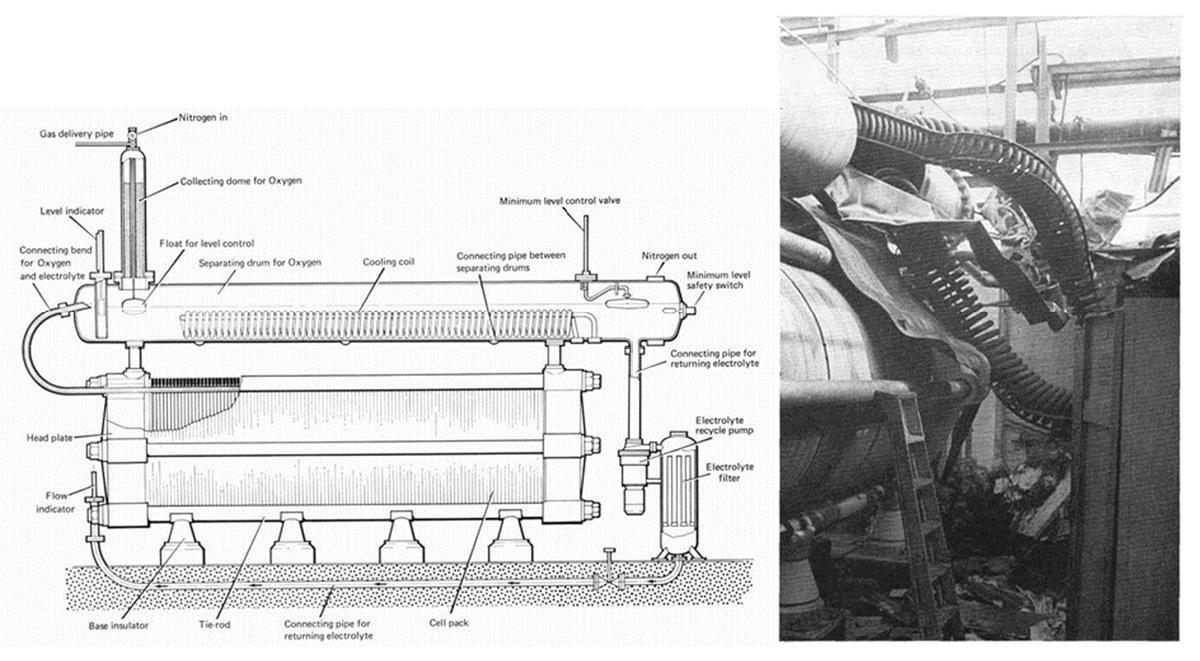
Figure 3
Laporte accident: drawing of the stack with the above oxygen separating drum (left) and a photograph of those components after the explosion (right) (HSE 1976).
The main lesson learned from this accident was that the principles of the legislation that regulates the thorough examination of steam boilers should be extended to the volumetric exterior components of an electrolyzer system, in particular to the phase and water separators for H2 and O2.
Both gas streams must be monitored by intrinsically safe continuous analyzers with interlinked visual and audible alarms when oxygen purity falls to 98.8% or hydrogen purity to 99.7%. The plant should shut down if oxygen purity falls to 98% or hydrogen purity to 99.5%.
The continuous catalytic cleaning via de-oxo and de-hydro reactors should be backed up by monitoring the gas qualities by hourly manual gas analyses carried out by the expert operators, and these in turn should be checked by a similar analysis by the laboratory. Clear instructions are needed.
The internal condition of the plant should be systematically monitored, such as sludge formation, cell voltages and temperatures, and gas/electrolyte temperature.
Appropriate positioning and passive blast protection walls around the phase separator and dryers will mitigate the effects of missiles and prevent escalation of the accident. Since the operator died from caustic burns caused by spilled potassium hydroxide, a passive protection of staff and vulnerable system components against larger spills of those aggressive chemicals should be considered.
At the Hong Kong Castle Peak power station, hydrogen for generator cooling and water conditioning was produced in an onsite alkaline electrolyzer system, with stacks operated at atmospheric pressure. On August 28, 1992, engineers at the power station warned of a problem before an explosion ripped through the New Territories plant.
Two high-pressure hydrogen cylinders (2 × 6.5 m3 @ 11 MPa/13.6 MPa_max) blew up (Figure 4). Larger fragments traveled up to 500 m. Missiles and debris killed two, injured 18 staff members, and wrecked concrete blast walls. In the post-accident examination, it turned out that the cylinders contained detonable H2/air mixtures.
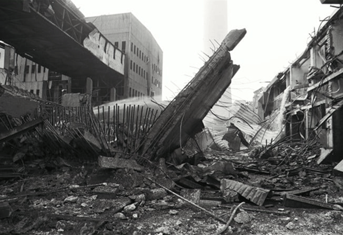
Figure 4
Blast of two large high-pressure storage cylinders destroying the Castle Peak power station electrolyzer site in 1992; Photo: SCMP.
The examination also found that, due to operational issues, air was sucked into the hydrogen side before the first compressor stage. The oxygen detection on the high-pressure side did not work properly, as the mixing of hydrogen and oxygen air, respectively, is suppressed by the pressure-dependent transport parameters. The actual ignition source is unknown. However, hydrogen-oxygen and hydrogen-air mixtures at high pressure are prone to ignition by even small pressure fluctuations.
The main conclusion was that, especially for atmospheric electrolyzers, inherent safe design must prevent air ingress in particular before first compression. Air/O2 detection in the pressurized H2 system part should be continuous, appropriate, and diverse. Effectively, this accident might be associated rather with any low-pressure hydrogen production technology and compression system than attributed to the electrolysis specifically.
In a more recent accident in May 2019, a devastating hydrogen tank explosion occurred at a power-to-gas testing site of the solar hydrogen demonstration and research site at Gangneung, South Korea (Figure 5). The cause of the explosion was found to be a massive oxygen-to-hydrogen crossover that happened at the alkaline electrolyzer under low-power operating conditions. There was no obvious erosion or perforation of the separators or electrodes found, like in the Laporte case.
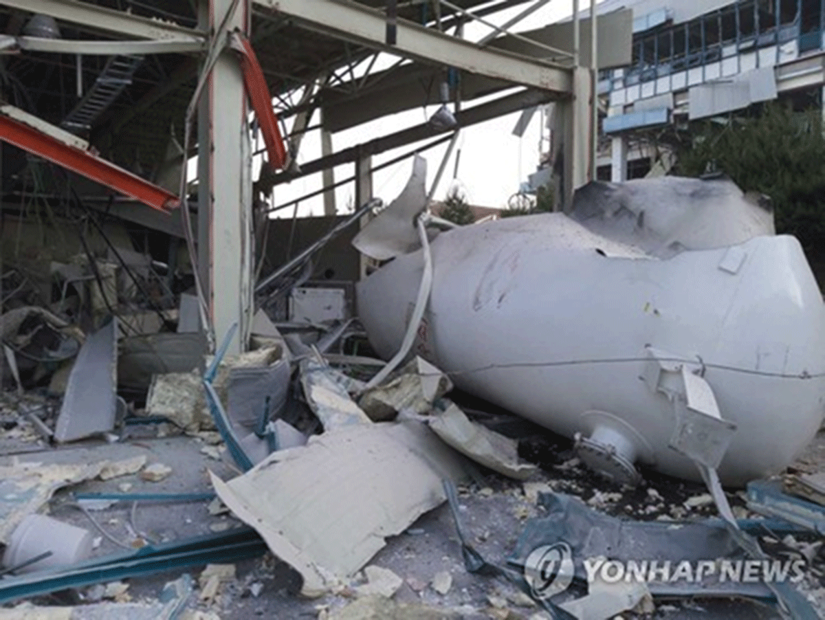
Figure 5
Blasted hydrogen storage cylinder at Gangneung accident, May 2019; Photo: YONHAPNEWS.
The crossover was not detected. Thus, an explosive mixture of hydrogen and oxygen formed in at least one of the two large hydrogen storage containers, each with about 40 m3 free volume, nominally operated at maximum pressures of 0.9 and 1.1 MPa, respectively. The ignition source is also unknown for this accident. Again, a fast-closing valve or strong acoustic shocks could ignite, in particular, hydrogen-oxygen mixtures at those elevated pressures. The explosion destroyed the other pressure vessel, killed two persons, injured six persons, and destroyed buildings in a radius of about 100 m. The damage to property was estimated at 30 million US dollars. Based on the near field damage, a TNT equivalent of the explosion strength of 50 kg was estimated (Kim et al. 2019).
According to a preliminary technical analysis, the plant showed design deficiency, lacked preventing and mitigating measures like de-oxo catalytic devices, and was operated at out-of-specification conditions.
These shortcomings need to be corrected, for example, by providing an in-situ diagnostic system able to trigger emergency stops of the hydrogen production system and automatic isolation of the storage tanks. The requirements for gas purification in electrolyzers should be fostered.
Generally, a better understanding of the relationship between the gas permeability of the electrolyzer membrane and the dynamic operation range caused by the variability of renewable power sources is required.
Based on this better understanding, standardized performance and safety tests should be developed or adjusted, aiming to define more realistic testing requirements and conditions at partial/low load cycles in ISO 22734:2019 ‘Hydrogen generators using water electrolysis’ (ISO 2019), for instance.
Pressure vessels should be protected against domino mode, by setback distances or protective walls accounting for catastrophic vessel failure as a potential scenario of similar setups.
8. Conclusion and Next Steps
This paper has provided an overview of electrolyzer processes and technologies, electrolyzer hazard identification, leak scenarios, safety distances, risk mitigation, and existing RCS. It provides insight on the most impactful scenarios that should be considered when defining safety distances. However, several of these scenarios can be eliminated, and the corresponding safety distances can be significantly reduced if the appropriate prevention and mitigation barriers are implemented and correctly applied. The insights presented herein are based upon the collaborative efforts of industry experts comprising the IEA TCP Task 43 Task Force and can be applied by electrolyzer manufacturers, operators, and regulatory authorities.
The following are the next steps and gaps that need to be addressed for defining safety distances:
consider harmonization of the harm criteria
develop modeling approaches for hydrogen consequences for detonation and DDT, projectiles (typical projectiles)
agreement on the leakage frequencies and proper definition of ignition probabilities (The results are partially available in a technical report (Groth et al. 2024), in preparation for journal submission and in HyRam.)
scientific investigation of the most appropriate reference hole size
complete electrolyzer quantitative risk assessment for electrolyzers to support risk-informed prioritization of safety measures. (Recent QRA modeling efforts by the University of Maryland and EPRI have provided detailed insight into a PEM electrolyzer configuration (Groth et al. 2024; Al-Douri et al. 2025). These efforts should be extended to additional electrolyzer configurations to provide risk-informed prioritization of electrolyzer safety measures)
This paper does not include tables presenting specific safety distances to be applied around electrolyzers, since these values:
are dependent on the gaps highlighted above,
to be of use, it would need to follow a methodology that is harmonized worldwide.
Acknowledgements
This work has been achieved in the framework of subtask C-Safety Distance Methodologies of the IEA TCP Task 43 – Safety and RCS of Hydrogen Energy Applications led by Dr. Andrei V. Tchouvelev and Dr. Elena Vyazmina.
Competing Interests
Thomas Jordan and Sebastian Quesnel are members of the editorial board for Hydrogen Safety but had no involvement in any editorial processes related to the handling of this submission. All other authors have no competing interests.