
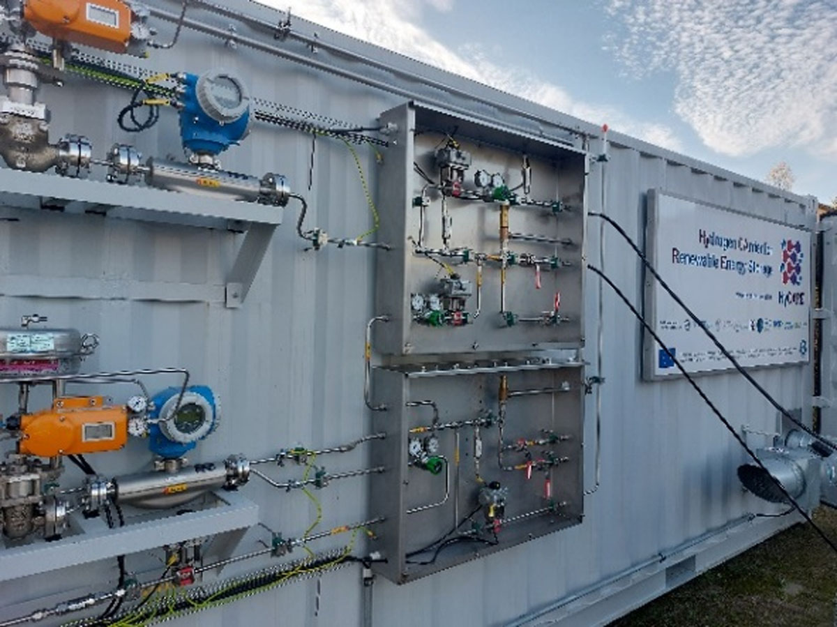
Figure 1
HyCARE container. View of the inlet and outlet manifold on the external wall of the container. Photo. Stühff Maschinen- und Anlagenbau GmbH. Reproduced with permission of the company.
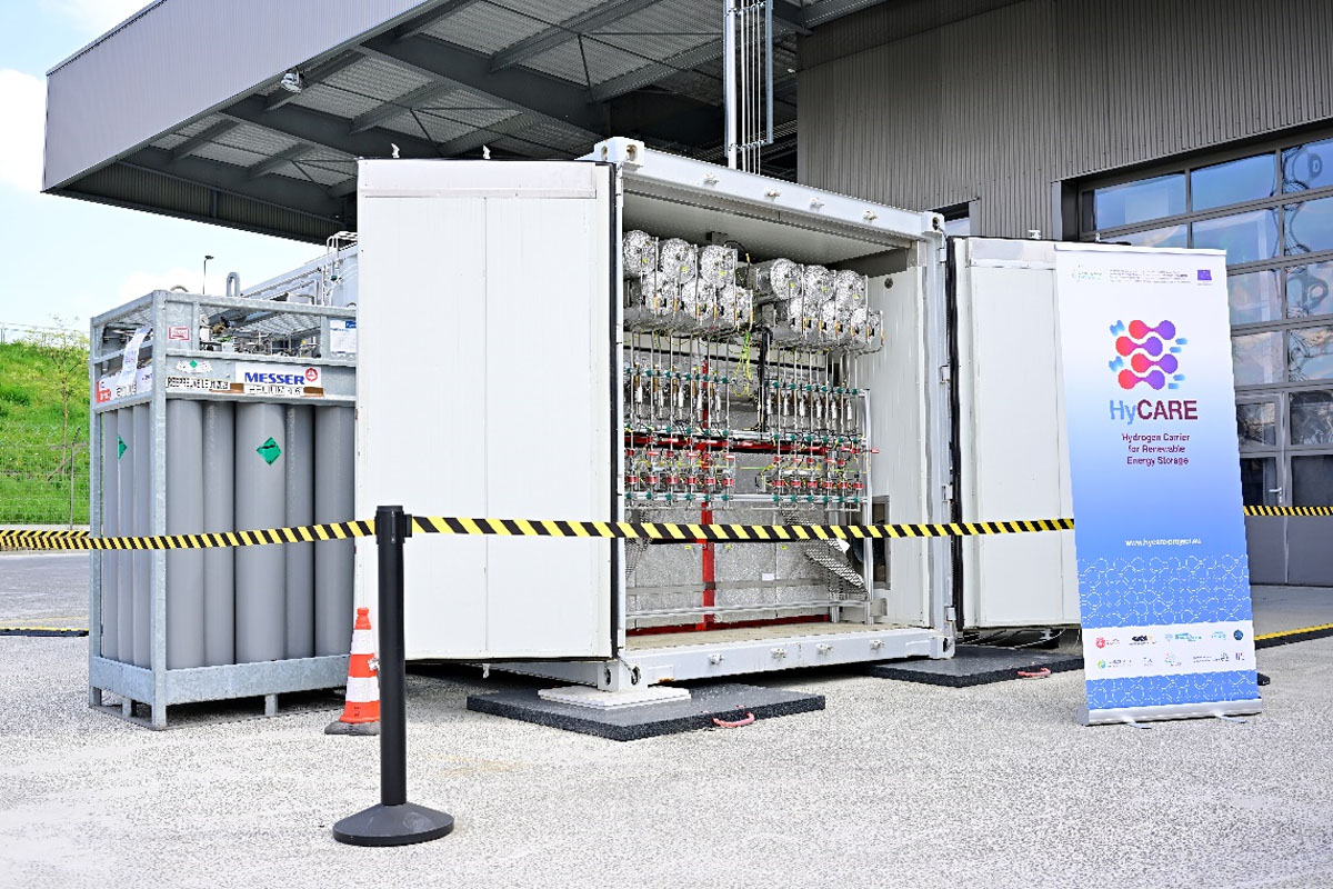
Figure 2
View of the container with its doors open showing the MH and PCM tanks inside. Photo. (c) ENGIE Lab CRIGEN/Franck Dunouau, 2023. Reproduced with permission of the company and photographer.
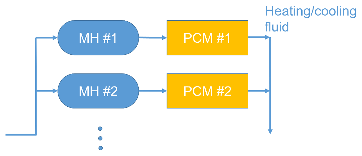
Figure 3
Representation of two of the twelve units installed inside the container composed by a MH tank thermally coupled with a PCM tank. Modified from reference Capurso 2020.
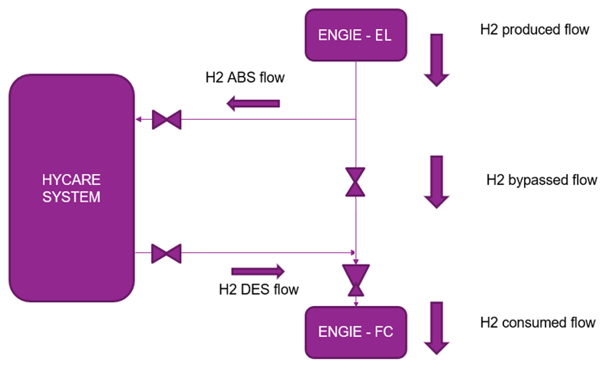
Figure 4
Integration of the project and boundaries.
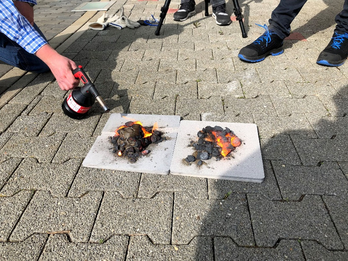
Figure 5
Heating of solid metal hydride blocks with a blowtorch for 2.5 minutes (right) and 4.5 minutes (left) showing slow spread of flame front. Photo GKN. Reproduced with permission of the company.
Table 1
Additional safety experiments.
| EXPERIMENT | AUTO-IGNITION | OBSERVATIONS |
|---|---|---|
| MH in air at ambient conditions | No | The MH cooled down slowly |
| MH submerged in water at ambient conditions | No | approx. 6 mL of H2 (gas) released per cm3 of MH |
| MH directly exposed to blowtorch (2.5 min) | N/A | approx. 1500°C max., slow flame front spreading |
| MH directly exposed to blowtorch (4.5 min) | N/A | approx. 1700°C max., slow flame front spreading |
Table 2
Severity levels considered in the risk assessment of the semi-quantitative HAZOP.
| SEVERITY LEVEL | 1-INSIGNIFICANT | 2-MARGINAL | 3-CRITICAL | 4-SEVERE |
|---|---|---|---|---|
| Near miss. | Minor accident. | Major accident. | Disastrous accident. | |
| No person injured or only first aid. | Person injured with irreversible effects. | Person injured with irreversible effects. | One fatality. |
Table 3
Likelihood levels considered in the risk assessment of the semi-quantitative HAZOP.
| LIKELIHOOD LEVEL | 1-IMPROBABLE | 2-RARE | 3-OCCASIONAL | 4-LIKELY | 5-CERTAIN |
|---|---|---|---|---|---|
| Rarely happened in the industry. | Unheard of in the company. | Has occurred in the company. | Occurs several times per year in the company. | Occurs several times per year in the same area. |
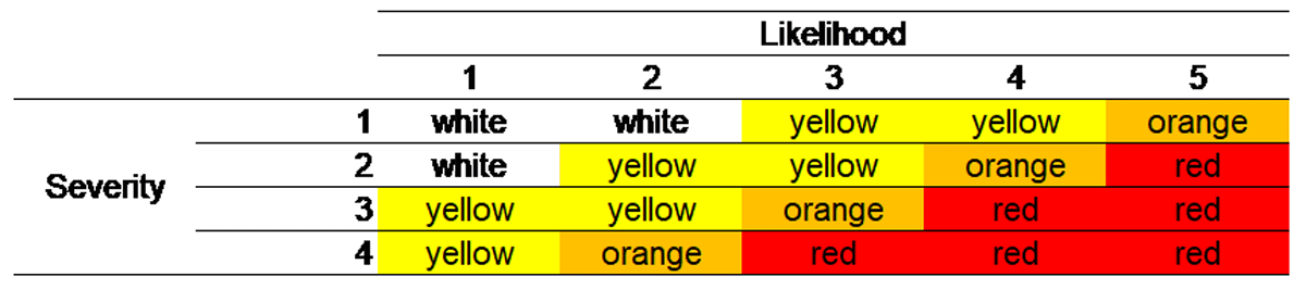
Figure 6
Matrix for risk assessment.
Table 4
Risk levels considered in the risk assessment of the semi-quantitative HAZOP.
| RISK LEVEL | DEFINITION |
|---|---|
| Insignificant risk (white zone) | Risks that are considered insignificant, due to the level of impact (severity and likelihood) and no significant deviations from relevant national/international regulations or company standards. Mitigation measures to be assessed based on ALARP principle and included in future plans. Classification NOTE only. |
| Low risk (yellow zone) | Risks that are considered low due to the level of impact (severity and likelihood) and no significant deviations from relevant national/international regulations or company standards. Mitigation measures to be assessed based on ALARP principle and included in future plans. Classification CAUTION. |
| Medium risk (orange zone) | Risks that are considered medium due to the level of impact (severity and likelihood). Mitigating measures to reduce risks have to be identified and discussed with local management and implemented based on ALARP principle for relevant risks. Classification WARNING. |
| High risk (red zone) | Risks that are considered high either due to the level of impact (severity and likelihood) and/or significant deviations from relevant national/international regulations or company standards. Mitigating measures to reduce risks have to be identified and evaluated. Attention from higher level management shall be given if efficient mitigation is not identified and decided. To further evaluate the risks, more detailed analysis could be performed. The risks may then be compared to more detailed risk tolerance criteria. Classification DANGER. |
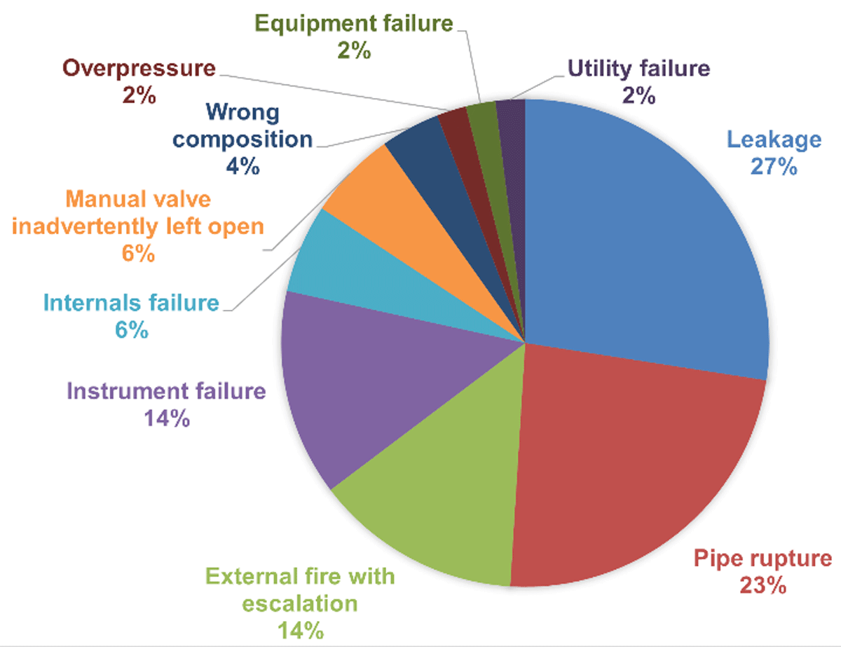
Figure 7
Identified cause distribution of the scenarios with safety consequences during HAZOP study.
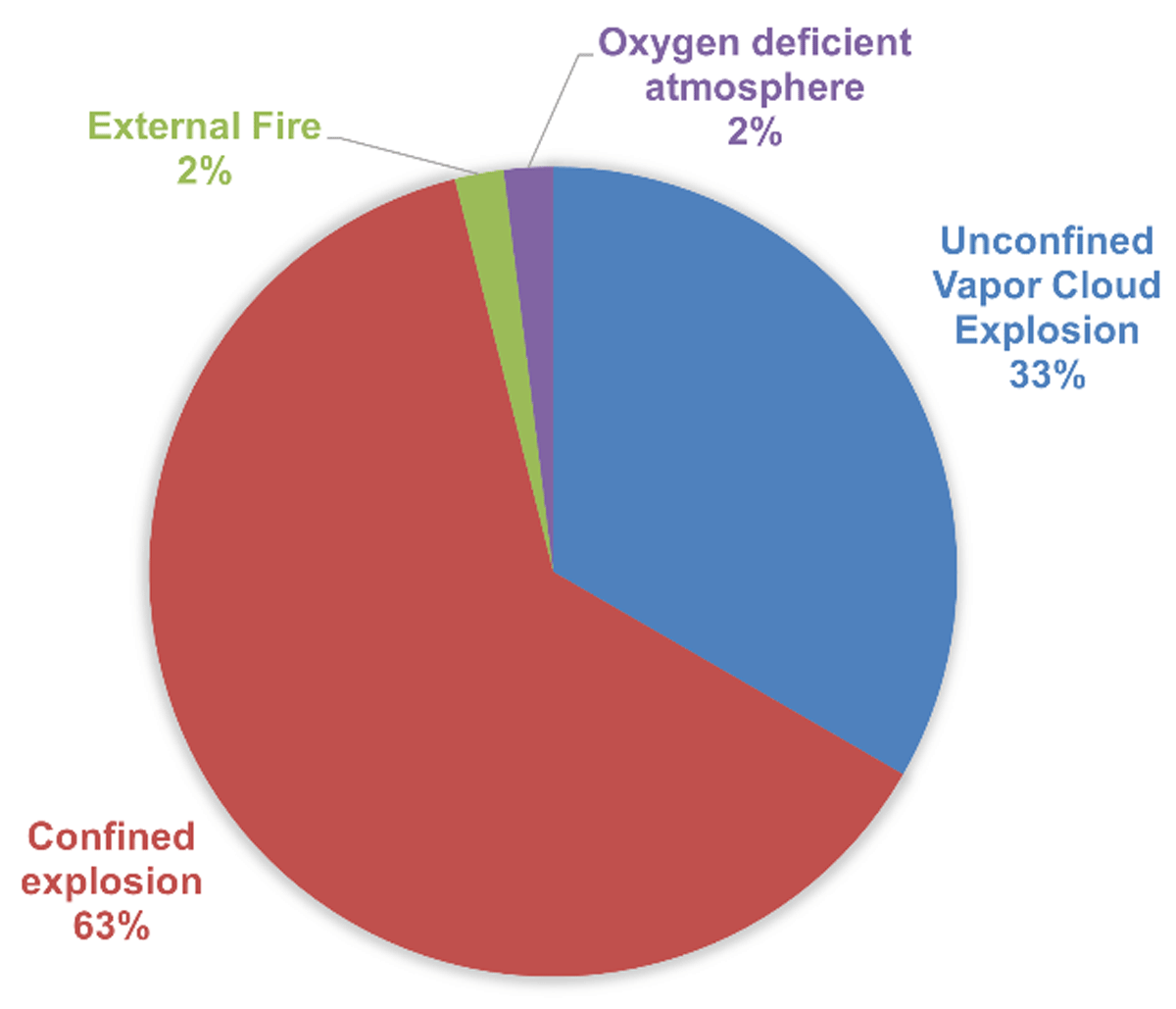
Figure 8
Event category distribution by number of scenarios with safety consequences from HAZOP study.
Table 6
Methodologies chosen to perform a consequence analysis for critical scenarios in HyCARE demonstrator.
| SCENARIO | CAUSE | CONSEQUENCE ANALYSIS METHODOLOGY |
|---|---|---|
| Unconfined explosion due to hydrogen release | Pipe rupture | Dispersion and explosion simulation in Phast 8.22 from DNV |
| Sampling valve open | ||
| Relief through damage to TFV loop | Dispersion and explosion simulation in Phast 8.22 from DNV | |
| Misdirected flow of hydrogen to other areas | Dispersion and explosion simulation in Phast 8.22 from DNV | |
| Explosion inside MH-tanks due to air-hydrogen mixture*, with potential escalation | Air ingress in the system due to human error | Confined explosion simulation through Brode energy calculation and applying TNO Multi-Energy method. |
| Insufficient flow of nitrogen (argon) | ||
| Confined Explosion in container | Programmable Logic Controller (PLC) failure and temperature decrease producing hydrogen leakage | Explosion analysis through simulation in FLACS software from GEXCON. The flammable volume in the container is defined by dispersion analysis of two different sizes of leakage and three different ventilation conditions. |
| Exceeding hydrogen loop design pressure | ||
| Asphyxiating atmosphere | Argon leakage and accumulation in container | Non credible upon implementation of HAZOP recommendations. Managed through HAZOP actions follow-up process by calculating the time and flowrate of the ventilation required to ensure adequate oxygen levels in the container. The ventilation parameters and mandatory use of personal oxygen detector are included in the operating manual. |
[i] Note: *This scenario is related to the mixture of the hydrogen on the gaseous phase with unexpected air presence. Note that reactivity of the hydride material with air or water is observed to be low (see 3.1), therefore not contributing to this type of scenario.
Table 7
Summary table of consequence analysis results in terms of safety distances for critical scenarios related to hydrogen release.
| REF. | SCENARIO DESCRIPTION | METHOD | EFFECT DISTANCES (m) | |||
|---|---|---|---|---|---|---|
| WINDOWS BROKEN | IRREVERSIBLE EFFECTS TO HUMAN LIFE | LETHAL EFFECTS | SERIOUS LETHAL EFFECTS | |||
| 1-u | Pipe rupture on H2 supply (outdoor)–UVCE | Phast-Multi- Energy | 40 | 20 | 11 | 10 |
| 1-jf | Pipe rupture on H2 supply (outdoor)–Jet fire | Phast | – | NSE (NSD–limited duration release; flash fire effects yield more conservative distances) | ||
| 1-ff | Pipe rupture on H2 supply (outdoor)–Flash fire | Phast | – | 13 | 12 | – |
| 2-u | H2 relief through damage to TFV loop. Release by safety valve–UVCE | Phast-Multi- Energy | NSE | |||
| 2-jf | H2 relief through damage to TFV loop (water glycol loop). Release by safety valve–Jet fire | Phast | – | NSE (NSD–limited duration release; flash fire effects yield more conservative distances) | ||
| 2-ff | H2 relief through damage to TFV loop. Release by safety valve–Flash fire | Phast | – | NSE at operator height (6.2 m at release height (110% LFL)) | NSE at operator height (5.6 m at release height (100% LFL)) | – |
| 3 | Explosion inside MH- tanks with escalation (air presence in the tanks & ignition of H2-air mixture with escalated loss of containment and VCE in container) | Brode – Dispersion CFD and Multi-Energy | 48 | 24 | 11 | 7 |
| 4 | Confined explosion in container | FLACS CFD | 36 | 18 | 15 | 7.5 |
[i] Notes: All distances are expressed in meters in the horizontal plane; ‘-’ means not applicable; NSE means that no significant effects are observed for reference thresholds; NSD means non-sufficient thermal radiation dose and there is no flame impingement on nearby equipment or structures.