
1.0 Background and Context
Hydrogen tanks are required to store hydrogen after its production (e.g. by electrolysis) and before its utilization (e.g. fuel cell or compression). Current approaches for renewable energy storage in Europe are inefficient and require a large footprint. Only prototype systems have been available up to now, but hydrogen carriers have the potential to overcome these challenges, yet large-scale applications are still evolving from a demonstration to an industrial scale-up phase. One of the options to decrease the cost of hydrogen storage significantly, and to maximize the safety of the storage, is to use metal hydride hydrogen storage systems, which can be easily integrated in existing and commercial hydrogen facilities. The use of metal hydrides allows a high storage capacity at a much lower storage pressures (reducing safety distances) compared to the usual high-pressure storages required to achieve equivalent energy densities (i.e., MH allows for a smaller footprint for the equivalent mass of hydrogen in the storage). The innovative approach for storing hydrogen at low pressure and low footprint that was studied in the Clean Hydrogen Partnership (former Fuel Cells and Hydrogen Joint Undertaking [FCHJU]) project HyCARE, consisted in coupling a metal hydride, that is used as hydrogen carrier, with a PCM that is used as storage of the reaction heat related to the hydrogen absorption in the metal hydride. The stored reaction heat then assists the desorption reaction to provide hydrogen to downstream consumers.
This funded European project answering to the call H2020-JTI-FCH-2018-1 was achieved by a consortium with leading research groups on solid-state hydrogen carriers. The project consortium is composed by highly skilled research institutes, small and medium sized enterprises and large corporations in the energy sector. The University of Turin (Italy), Fondazione Bruno Kessler through the Center for Sustainable Energy (Italy), Helmholtz-Zentrum hereon GmbH (Germany), IFE (Institute for Energy Technology [Norway]) and the CNRS (Centre National de la Recherche Scientifique [France]) provided high-level knowledge and expertise in the development and characterization of metal hydrides for hydrogen storage, structural, chemical, thermo- and fluid-dynamic characterization, system modeling, design, construction and testing. GKN Hydrogen (a spin-off of GKN Sinter Metals Engineering GmbH [Germany]), Tecnodelta Impianti Srl (Italy) and Stühff Maschinen- und Anlagenbau GmbH (Germany) provided the key components of the HyCARE system. The HyCARE demonstrator was installed and integrated for operation at ENGIE research and innovation Lab CRIGEN.
The main objectives of the HyCARE project are:1
Couple hydrogen storage with thermal energy storage, providing improved energy efficiency
Store a high quantity of hydrogen, up to 40 kg
Integrate the prototype system with a real application (proton exchange membrane [PEM] electrolyser and a PEM fuel cell)
Improve safety of hydrogen storage:
low pressure (<50 bar)
low temperature (<100°C)
production and handling of metal hydride material in air, without protective atmosphere
No hydrogen compression steps necessary
Innovative design, reducing the footprint of the storage system
Store and deliver hydrogen at high purity (>99.99%)
In order to achieve these objectives, a demonstrator was built with metal hydride storage tanks in a maritime 20-foot container to test metal hydride capacity and efficiency in a typical configuration of hydrogen facilities between a producer (PEM electrolyser) supplying 10 Nm3/h and a consumer (fuel cell) with 20 kW power.
The hydrogen is absorbed and released by metallic hydrides in a reversible reaction depending on appropriate temperatures and pressures applied in the tank. For this project, a TiFe-based compound was selected as a low-cost and efficient, technically mature and potentially industrially scalable intermetallic compound storage for solid-state hydrogen storage under mild conditions.
The core of the article is based on the preliminary and detailed risk assessment (through hazard and operability study methodology [HAZOP]) along with the consequence analysis performed for the project. The main aspects of such studies are described in the following sections. Additional later experimental test results are included where relevant.
2.0 HyCARE Demonstrator Description
2.1 Equipment
Up to 40 kilograms of hydrogen are stored at less than 50 barg and less than 100°C in a 20-foot container. The innovative design is based on a maritime container (see Figure 1), including 12 TiFe metal hydride hydrogen storage tanks coupled with a thermal energy storage in PCM.
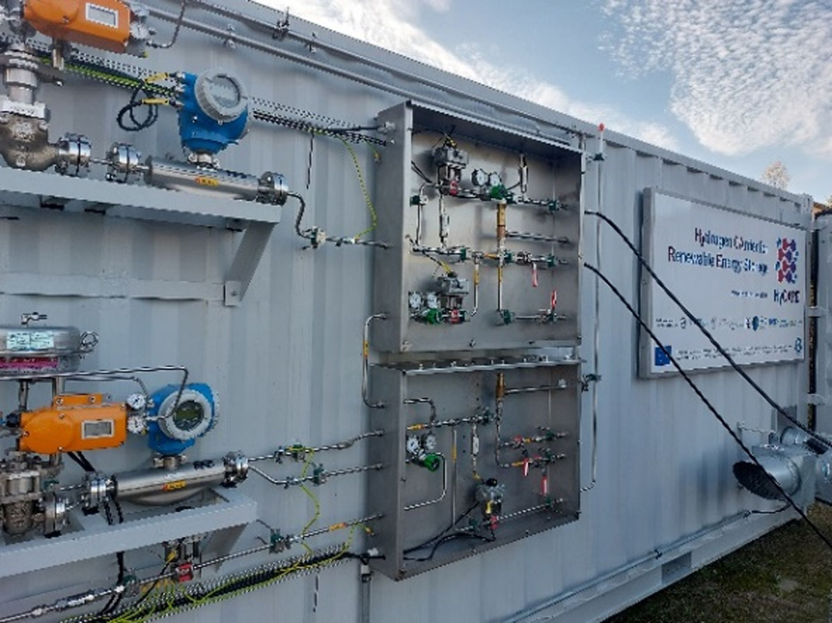
Figure 1
HyCARE container. View of the inlet and outlet manifold on the external wall of the container. Photo. Stühff Maschinen- und Anlagenbau GmbH. Reproduced with permission of the company.
The HyCARE hydrogen-heat-storage system consists of a complex construction, composed of several units/modules linked together and connected with different loops, which manage different fluids (Capurso, 2020). Fluids involved in the system are the following:
Hydrogen gas
Cooling/heating water-glycol solution
Nitrogen for instrumentation valve operation
Argon for inertisation of the HyCARE hydrogen-carrying equipment
The system implements the recovery of the heat released during the hydrogen absorption in the hydride by storing it in the PCM, which is placed in 12 fixed tanks on the lower part of the container, each connected to one MH tank. This heat transfer between MH tanks and the PCM is performed via the cooling/heating fluid (or Thermal Fluid Vector [TFV], non-flammable non-toxic water-ethylene glycol mixture); this energy is later used during the desorption phase. The losses of energy through the insulation are supplied by an external source (solar panels where possible). The amount of heat to be stored in the PCM tank is correlated to the amount of hydrogen stored in the HyCARE system and correspondingly, to the reversible storage capacity of the metal hydride. Thus, it was assumed 50 kg of hydrogen stored reversibly in the whole system and 1% as the reversible capacity of the TiFe alloy due to operational temperature limitations.
As illustrated in Figure 2, the tanks are physically integrated in the container in such way that the hydride tanks are above the PCM tanks.
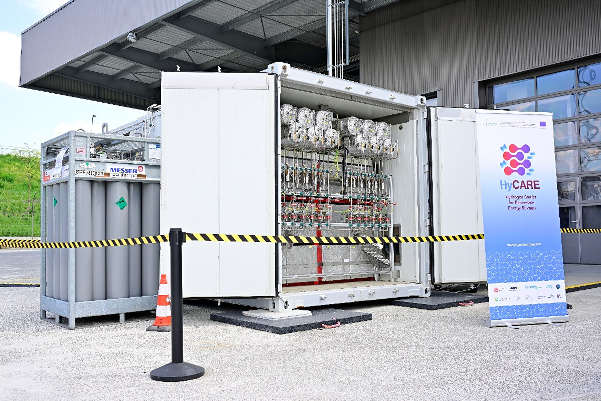
Figure 2
View of the container with its doors open showing the MH and PCM tanks inside. Photo. (c) ENGIE Lab CRIGEN/Franck Dunouau, 2023. Reproduced with permission of the company and photographer.
2.2 Operation
The HyCARE system aims to couple the hydrogen sorption processes in metal hydride with the phase change processes of a PCM over the heating/cooling fluid, as stated above. The different elements are organized as described in Figure 3. The goal is to store and recover the heat released and absorbed by the hydrogen absorption and desorption in the metal hydride, via the PCM. During the absorption process (ABS), the phenomenon is enabled when the inlet pressure of hydrogen to the MH-Tanks is above the equilibrium pressure for the material. Since the equilibrium absorption pressure depends on the actual temperature of material, the temperature of the absorption shall be controlled. Similarly, the desorption process (DES) is enabled when the outlet pressure of hydrogen from MH-Tanks is below the equilibrium pressure for the material. In the same way, the equilibrium pressure for hydrogen desorption depends on the actual temperature of material.
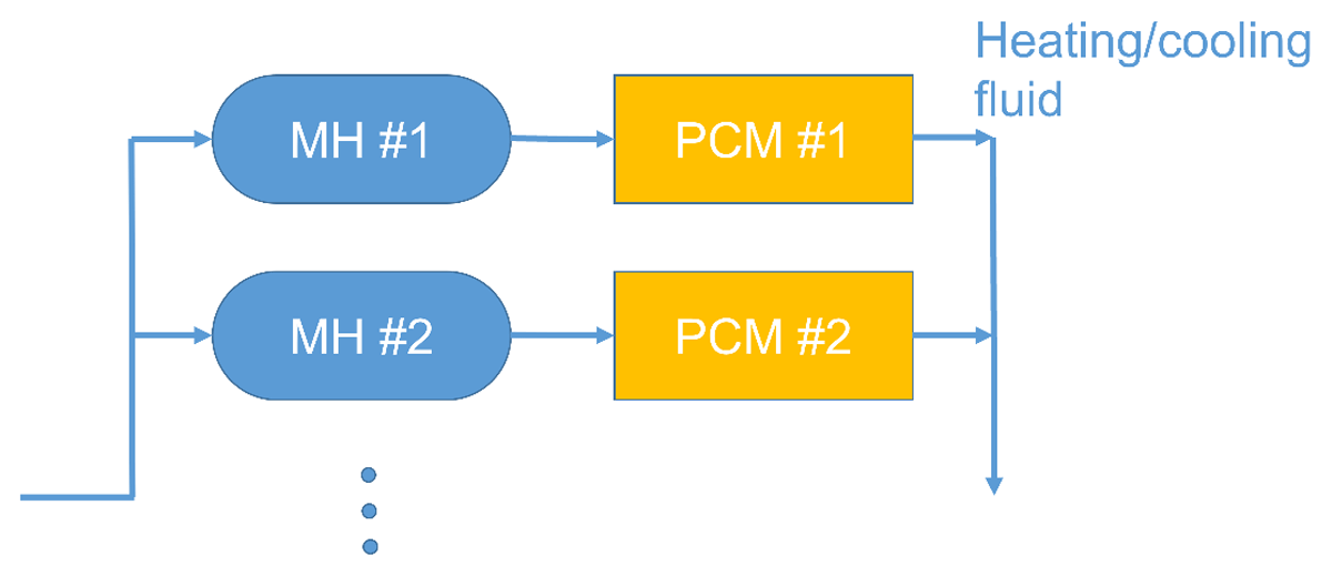
Figure 3
Representation of two of the twelve units installed inside the container composed by a MH tank thermally coupled with a PCM tank. Modified from reference Capurso 2020.
In regard to the integration with the electrolyser (EL) and the fuel cell (FC), with respect to the hydrogen flow, (see Figure 4), the HyCARE system shall be passive with respect to hydrogen production and utilization. This requires that, besides the absorption and desorption modes associated to the processes described above, the system shall also be capable to transfer directly the hydrogen produced from the electrolyser to the fuel cell; this is resolved by accommodating a bypass that allows this operation when required.
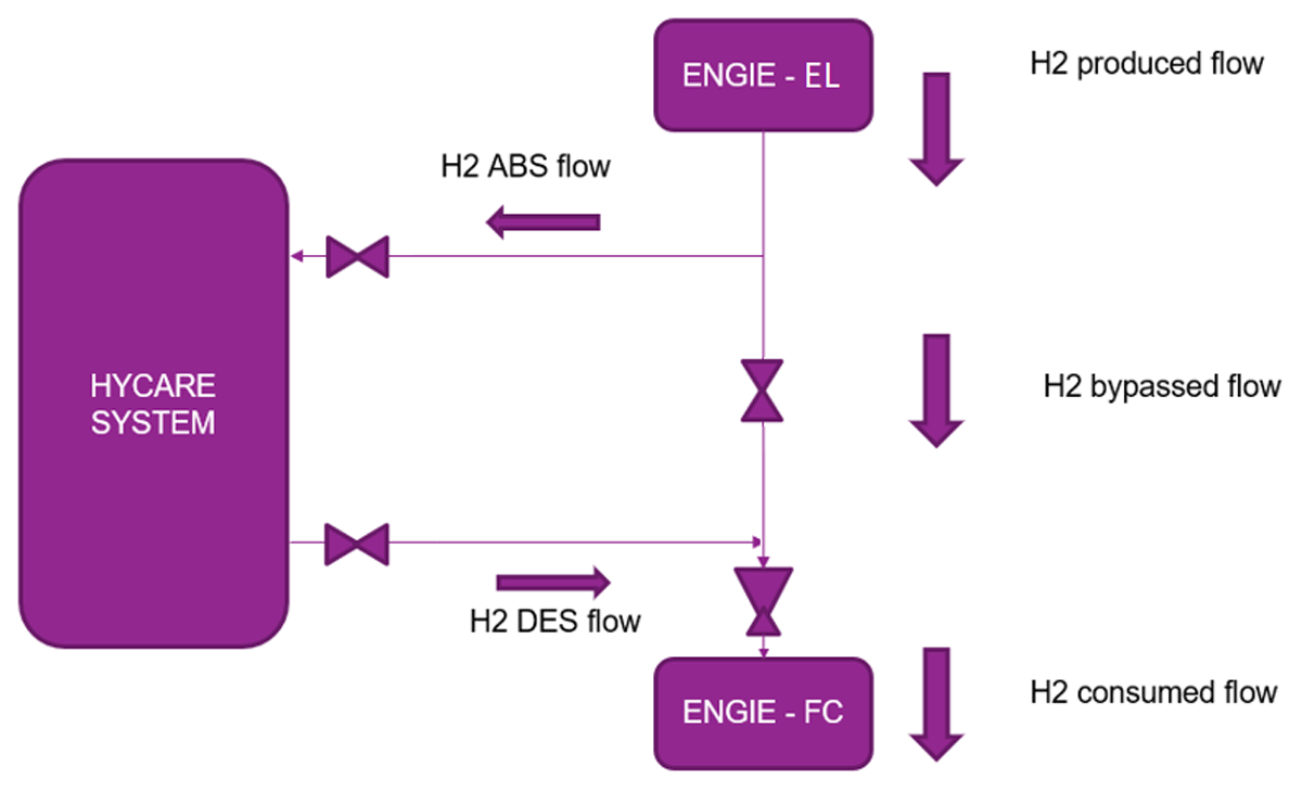
Figure 4
Integration of the project and boundaries.
3.0 Solid-State Carrier Storage Related Risks
3.1 Solid phase risks (MH)
The main risk with some metal hydrides is its accidental oxidation in contact with oxygen or water leading to an exothermic reaction with a risk of explosion in a tank. Oxygen could come from a failure of an electrolyser system upstream, or from an unintentional ingress of air in the tank from utilities or upstream systems. Water could come from a failure of the electrolyser system upstream as well, or contamination from auxiliary loops.
In HyCARE demonstrator, by filling the tank with compacted metal hydride pellets, the presence of dust is limited and its reactivity with air and/or water is drastically reduced. This leads to the advantage of operational safety (no auto-ignition) on the one hand, and on the other hand, to a simple and cheaper large-scale production, handling, storing, transporting and processing under normal air atmosphere in the HyCARE.
The injection of nitrogen, or argon (available utility gases), in HyCARE MH tanks has no safety consequences. Argon is used for flushing instead of nitrogen to avoid deactivation of the hydride. The deactivated hydride would not absorb hydrogen in the absorption phase, which is an operational deviation but not a safety issue.
Tests were carried out on activated MH, used for HyCARE project, to exclude the possibility of auto-ignition of the hydride in air and water. The hydride pellets were also heated up with a blowtorch, in air (see Figure 5), and the temperature reached and the flame front progress through the solid blocks with time were measured. Two heating times were used: 2.5 and 4.5 minutes. The results from such GKN Hydrogen tests (GKN Hydrogen, 2022) are shown in Table 1.
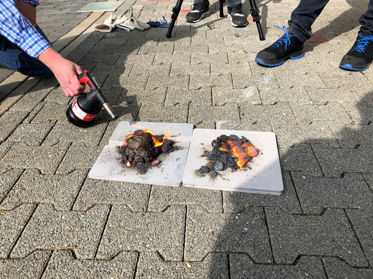
Figure 5
Heating of solid metal hydride blocks with a blowtorch for 2.5 minutes (right) and 4.5 minutes (left) showing slow spread of flame front. Photo GKN. Reproduced with permission of the company.
Table 1
Additional safety experiments.
| EXPERIMENT | AUTO-IGNITION | OBSERVATIONS |
|---|---|---|
| MH in air at ambient conditions | No | The MH cooled down slowly |
| MH submerged in water at ambient conditions | No | approx. 6 mL of H2 (gas) released per cm3 of MH |
| MH directly exposed to blowtorch (2.5 min) | N/A | approx. 1500°C max., slow flame front spreading |
| MH directly exposed to blowtorch (4.5 min) | N/A | approx. 1700°C max., slow flame front spreading |
When the MH used in HyCARE is in contact with oxygen, a passivation layer builds up at the MH surface and it deactivates (i.e. it cannot absorb hydrogen in normal absorption operating conditions) (GKN Hydrogen, 2023a). This layer of protective oxide prevents further oxidation which is crucial safety-wise since it avoids a runaway.
Hydride pellets are subjected to expansion due to the increase of the hydrides volume after activation. This increase of the hydrides internal volume could generate dilatation and/or deformation of the tank and therefore lead to tank damage. The state-of-the-art design of the pellet and the tank allows for expansion so the activated (expanded) MH grows exactly to the inner tank wall. In HyCARE project, the resulting forces, through MH expansion and gaseous hydrogen pressure to the tank walls, has been measured by GKN Hydrogen and do not exceed the maximum pressure of the tank design under any circumstances.
3.2 Gaseous phase risks (hydrogen)
According to lessons learned with other hydride materials, through other projects in the USA, (Hydrogen Tools, 2009), control of the charging pressure is one of the most crucial parameters. Although storage is at low pressure, the pressure increase, depending on the charging conditions, can be much steeper than expected when looking at the manometric loading pressure, due to fast increases in temperature following the exothermic absorption reaction. This can lead to accidental release of hydrogen.
From a preliminary risk assessment in HyCARE project (Quesnel et al., 2019), the main risk, related to the hydrogen storage system initially identified, was a loss of containment leading to different dangerous phenomena depending on the conditions and environment of the leak. These phenomena are related to the handling of hydrogen and are summarized below:
Jet fire in case of immediate ignition of hydrogen release
Flash fire in case of late ignition of hydrogen released in a free space
Unconfined vapor cloud explosion (UVCE) in case of late ignition outdoors with some congestion
Vapor cloud explosion (VCE) in case of late ignition of hydrogen released indoors (container)
The main causes for such hydrogen loss of containment identified in the preliminary risk assessment—without considering the safety barriers action—are:
Embrittlement
Corrosion
Overpressure (coupled with safety valve failure)
External aggression (i.e. mechanical damage from external sources such as vehicles or machinery)
Deviation on the system upstream (pressure, temperature, quality …)
Mechanical failure of equipment
Human error
Failure of utilities
The specific scenario related to the storage of hydrogen is the explosion of a hydrogen filled tank due to:
Accidental mix of hydrogen and oxygen in the tank followed by ignition
Overpressure from upstream system coupled to safety valve failure
Exposure of MH tanks to fire leading to wall failure and subsequent gaseous hydrogen ignition
It shall be noted that the gaseous phase in metal hydride storage systems is smaller in relation to conventional tanks. In case of HyCARE, only around 30% of the tank’s internal volume is free volume occupied by gaseous hydrogen. Furthermore, an explosion within the tank can only occur at the MH free gap. The explosion of the gas mixture inside the solid MH is ruled out by a pore size in the pellet smaller than the mean explosion gap limit (IEC 2010), meaning that the explosion cannot propagate to the next pore, similar to a technical flame barrier.
Additionally, given that the hydrogen desorption from the MH is an endothermic process, the contribution of the MH to the gas phase is limited by the desorption kinetics. GKN simulations (GKN Hydrogen, 2023b) showed that, in case of leakage, hydrogen leaves the MH tank with self-limiting speed, leading to a lower rate of hydrogen emission than, for example, from a pressure vessel of the same internal volume at an identical pressure.
4.0 Main Potential Risks Identified in Integrated HyCARE Demonstrator
4.1 Scenario identification and risk assessment methodology
4.1.1 Scenario identification
A HAZOP analysis was performed, from a process perspective, in order to systematically identify the hazardous scenarios in the HyCARE pilot plant, assess the initial risk (without safeguards), identify the existing barriers already incorporated into the design (safeguards), assess the residual risk (after safeguards) and define recommendations or actions if required to reach an acceptable risk level. A workshop was carried out with all the project partners. The main causes initiating scenarios with possible safety consequences are:
Equipment failure
External fire with escalation
Instrument failure
Internals failure
Leakage
Manual valve inadvertently left open
Overpressure
Pipe rupture
Power failure
Wrong composition of the gas
Since this study is a semi-quantitative HAZOP, when safety concerns were identified during the workshop, the severity and likelihood of each scenario were defined by the team according to Tables 2 and 3. The combination of severity and likelihood results in a certain risk level given by the risk matrix (see Figure 6) and as defined on Table 4.
Table 2
Severity levels considered in the risk assessment of the semi-quantitative HAZOP.
| SEVERITY LEVEL | 1-INSIGNIFICANT | 2-MARGINAL | 3-CRITICAL | 4-SEVERE |
|---|---|---|---|---|
| Near miss. | Minor accident. | Major accident. | Disastrous accident. | |
| No person injured or only first aid. | Person injured with irreversible effects. | Person injured with irreversible effects. | One fatality. |
Table 3
Likelihood levels considered in the risk assessment of the semi-quantitative HAZOP.
| LIKELIHOOD LEVEL | 1-IMPROBABLE | 2-RARE | 3-OCCASIONAL | 4-LIKELY | 5-CERTAIN |
|---|---|---|---|---|---|
| Rarely happened in the industry. | Unheard of in the company. | Has occurred in the company. | Occurs several times per year in the company. | Occurs several times per year in the same area. |
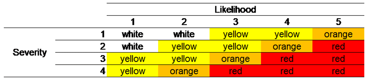
Figure 6
Matrix for risk assessment.
Table 4
Risk levels considered in the risk assessment of the semi-quantitative HAZOP.
| RISK LEVEL | DEFINITION |
|---|---|
| Insignificant risk (white zone) | Risks that are considered insignificant, due to the level of impact (severity and likelihood) and no significant deviations from relevant national/international regulations or company standards. Mitigation measures to be assessed based on ALARP principle and included in future plans. Classification NOTE only. |
| Low risk (yellow zone) | Risks that are considered low due to the level of impact (severity and likelihood) and no significant deviations from relevant national/international regulations or company standards. Mitigation measures to be assessed based on ALARP principle and included in future plans. Classification CAUTION. |
| Medium risk (orange zone) | Risks that are considered medium due to the level of impact (severity and likelihood). Mitigating measures to reduce risks have to be identified and discussed with local management and implemented based on ALARP principle for relevant risks. Classification WARNING. |
| High risk (red zone) | Risks that are considered high either due to the level of impact (severity and likelihood) and/or significant deviations from relevant national/international regulations or company standards. Mitigating measures to reduce risks have to be identified and evaluated. Attention from higher level management shall be given if efficient mitigation is not identified and decided. To further evaluate the risks, more detailed analysis could be performed. The risks may then be compared to more detailed risk tolerance criteria. Classification DANGER. |
4.1.2 Risk assessment results
The causes of the potentially hazardous scenarios identified during the HAZOP are shown in Figure 7 by numerical distribution.
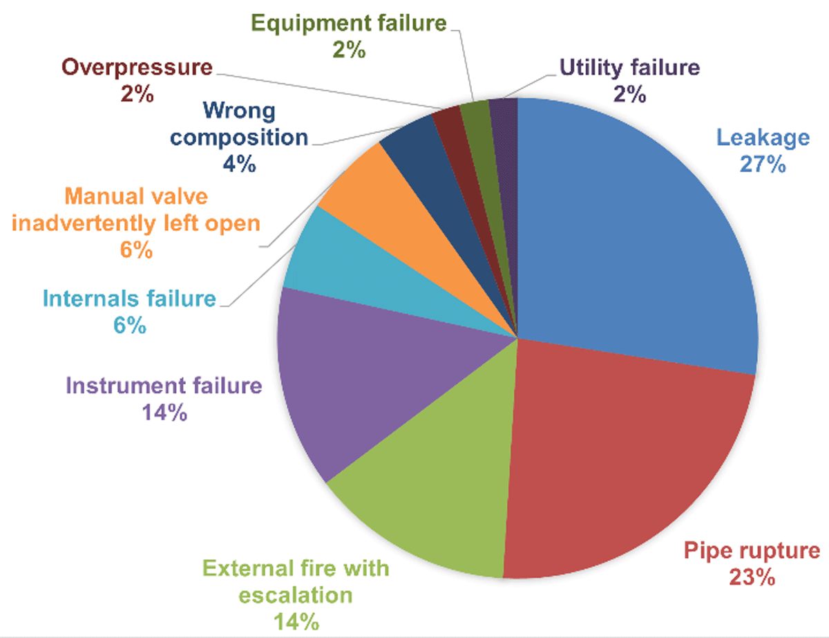
Figure 7
Identified cause distribution of the scenarios with safety consequences during HAZOP study.
The hazardous scenarios identified during the HAZOP fall in the following phenomenological categories:
Outdoor dispersion and UVCE
Confined explosion (either inside the container or inside the MH-tanks due to hydrogen-air mixture)
External fire
Oxygen deficient atmosphere
The distribution of the phenomena by number of scenarios is shown on Figure 8.
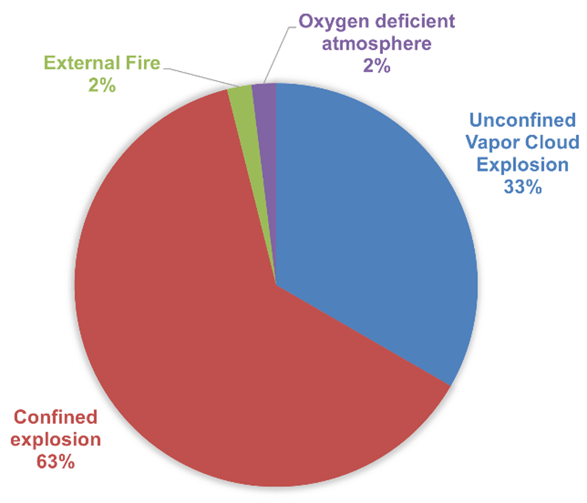
Figure 8
Event category distribution by number of scenarios with safety consequences from HAZOP study.
For all these scenarios, during the HAZOP study, the available safety barriers were also identified and additional recommendations were requested, if necessary, so that at the end of the analysis and the effective installation of the demonstrator, the scenarios were either ruled out (by eliminating the cause) or mitigated in such way that the residual risk is acceptable (white zone) or tolerable (yellow zone) as per Figure 6.
4.2 Main scenarios identified
The semi-quantitative risk assessment performed during the HAZOP workshop allowed the identification of critical scenarios to be analyzed in detail and effectively manage the risk. In this regard, the 19 critical scenarios identified, which correspond to the medium- and high-risk scenarios, are grouped and listed below. The vast majority belong to the hydrogen loop nodes, only three belong to other nodes; of which two are essentially caused by hydrogen hazards and only one is due to the inherent risk of argon (its capacity to displace oxygen in confined spaces and to generate asphyxiation). Argon as flushing gas can generate an asphyxiating atmosphere similar to nitrogen within the container, in case of leak. The consequences and related causes from the critical scenarios identified can be summarized as follows:
Unconfined explosion due to hydrogen release (outdoor dispersion and UVCE) caused by:
Pipe rupture (e.g. to overpressure from hydrogen supply)
Sampling valve remaining open
Relief through leakage into the TFV loop (ethylene glycol-water mixture)
Misdirected flow of hydrogen to other areas (e.g. contamination of argon)
Internal explosion inside MH-tanks with potential escalation caused by:
Air ingress in the system due to human error, mixing with hydrogen and explosion if ignited
Insufficient flow of argon causing air ingress, mixing and explosion if ignited
Confined explosion in container due to hydrogen release inside the container caused by:
Instrumentation failure and temperature decrease producing hydrogen leakage
Exceeding hydrogen loop design pressure
Asphyxiation or anoxia (oxygen deficient atmosphere) caused by argon (flushing fluid) or nitrogen (for pneumatic control of the valves) leakage and accumulation in container
As previously stated, all critical scenarios enumerated above were addressed through mitigation measures foreseen during the planning stages and implemented.
5.0 Consequence Analysis of Scenarios
5.1 Strategy for the consequence analysis of scenarios
A consequence analysis of high and medium risk scenarios—from now on called critical scenarios—was performed to understand the potential effects of such scenarios, and to reduce the severity of the events identified by ensuring an adequate design of protection safety features while considering the characteristics of the receiving site and its environment. As it is observed further on, the methodology chosen to study each of those critical scenarios is indicated in Table 6 and does not consider the safety barriers already implemented in the design. The main software used for the consequence analysis were Phast 8.22 (DNV, 2019) from DNV and the computational fluid dynamics (CFD) software FLACS-CFD v20.2 (GEXCON, 2023) from Gexcon.
Table 6
Methodologies chosen to perform a consequence analysis for critical scenarios in HyCARE demonstrator.
| SCENARIO | CAUSE | CONSEQUENCE ANALYSIS METHODOLOGY |
|---|---|---|
| Unconfined explosion due to hydrogen release | Pipe rupture | Dispersion and explosion simulation in Phast 8.22 from DNV |
| Sampling valve open | ||
| Relief through damage to TFV loop | Dispersion and explosion simulation in Phast 8.22 from DNV | |
| Misdirected flow of hydrogen to other areas | Dispersion and explosion simulation in Phast 8.22 from DNV | |
| Explosion inside MH-tanks due to air-hydrogen mixture*, with potential escalation | Air ingress in the system due to human error | Confined explosion simulation through Brode energy calculation and applying TNO Multi-Energy method. |
| Insufficient flow of nitrogen (argon) | ||
| Confined Explosion in container | Programmable Logic Controller (PLC) failure and temperature decrease producing hydrogen leakage | Explosion analysis through simulation in FLACS software from GEXCON. The flammable volume in the container is defined by dispersion analysis of two different sizes of leakage and three different ventilation conditions. |
| Exceeding hydrogen loop design pressure | ||
| Asphyxiating atmosphere | Argon leakage and accumulation in container | Non credible upon implementation of HAZOP recommendations. Managed through HAZOP actions follow-up process by calculating the time and flowrate of the ventilation required to ensure adequate oxygen levels in the container. The ventilation parameters and mandatory use of personal oxygen detector are included in the operating manual. |
[i] Note: *This scenario is related to the mixture of the hydrogen on the gaseous phase with unexpected air presence. Note that reactivity of the hydride material with air or water is observed to be low (see 3.1), therefore not contributing to this type of scenario.
The reference limits or thresholds are selected from the French legislation (JORF, 2005). These limits used in the consequence analysis are described below.
Four main thresholds are considered in this study in terms of overpressure:
50 mbar: threshold for irreversible effects that delimitates the boundary of the dangerous zone for human life and slight structural damage for property
140 mbar: threshold for lethal effects that delimitates the boundary of the serious danger zone for human life and serious structural damage for property
200 mbar: threshold for lethal effects that delimitates the boundary of the highly serious danger zone for human life and for domino effects over equipment
300 mbar: threshold for highly serious structural damage for property
For thermal effects (jet fire), the thresholds considered are as follows:
3 kW/m2 or dose of 600 [(kW/m2)(4/3)].s, threshold of irreversible effects
5 kW/m2 or dose of 1000 [(kW/m2)(4/3)].s, threshold of lethal effects
8 kW/m2 or dose of 1800 [(kW/m2)(4/3)].s, threshold of significant lethal effects
The effect distance of flash fire for irreversible effects on humans is considered 110% of the lower flammable limit (LFL) plume, and 100% for lethal effects. Flash fires do not generate effects on structures (domino effects) because of the short duration of the phenomenon.
5.2 Consequence analysis results
The dangerous phenomena related to the scenarios identified previously were assessed through consequence modeling leading to the effect distances detailed in the Table 7.
Table 7
Summary table of consequence analysis results in terms of safety distances for critical scenarios related to hydrogen release.
| REF. | SCENARIO DESCRIPTION | METHOD | EFFECT DISTANCES (m) | |||
|---|---|---|---|---|---|---|
| WINDOWS BROKEN | IRREVERSIBLE EFFECTS TO HUMAN LIFE | LETHAL EFFECTS | SERIOUS LETHAL EFFECTS | |||
| 1-u | Pipe rupture on H2 supply (outdoor)–UVCE | Phast-Multi- Energy | 40 | 20 | 11 | 10 |
| 1-jf | Pipe rupture on H2 supply (outdoor)–Jet fire | Phast | – | NSE (NSD–limited duration release; flash fire effects yield more conservative distances) | ||
| 1-ff | Pipe rupture on H2 supply (outdoor)–Flash fire | Phast | – | 13 | 12 | – |
| 2-u | H2 relief through damage to TFV loop. Release by safety valve–UVCE | Phast-Multi- Energy | NSE | |||
| 2-jf | H2 relief through damage to TFV loop (water glycol loop). Release by safety valve–Jet fire | Phast | – | NSE (NSD–limited duration release; flash fire effects yield more conservative distances) | ||
| 2-ff | H2 relief through damage to TFV loop. Release by safety valve–Flash fire | Phast | – | NSE at operator height (6.2 m at release height (110% LFL)) | NSE at operator height (5.6 m at release height (100% LFL)) | – |
| 3 | Explosion inside MH- tanks with escalation (air presence in the tanks & ignition of H2-air mixture with escalated loss of containment and VCE in container) | Brode – Dispersion CFD and Multi-Energy | 48 | 24 | 11 | 7 |
| 4 | Confined explosion in container | FLACS CFD | 36 | 18 | 15 | 7.5 |
[i] Notes: All distances are expressed in meters in the horizontal plane; ‘-’ means not applicable; NSE means that no significant effects are observed for reference thresholds; NSD means non-sufficient thermal radiation dose and there is no flame impingement on nearby equipment or structures.
The two worst case scenarios, with the highest effect distances, are explosion inside MH tanks due to air-hydrogen mixture and confined explosion in a container. It shall be noted that the explosion inside MH tanks scenario is not related to the use of a metal hydride, an explosion could only occur if atmospheric air is present inside the tanks because of an insufficient purging after maintenance or because of air contamination at upstream systems, unrelated to HyCARE, which are scenarios that would potentially be observed in any gaseous hydrogen storage system. Furthermore, the oxygen concentration coming from the upstream production systems feeding the demonstrator couldn’t exceed one percent due to the production technology selected, therefore contamination with oxygen from electrolysis was not a concern for the facility where it was installed.
The prevention and mitigation strategy to reduce the risk related to the potentially hazardous scenarios is summarized in the following section.
6.0 Prevention and Mitigation Strategies
In order to eliminate the risks, where possible, and to reduce others as low as reasonably practicable, the following prevention safety barriers were implemented. Most of these prevention safety barriers were already considered in the planning stage of the system (before the HAZOP was carried out) and similar storage systems could benefit from them:
Material adapted to hydrogen: selecting austenitic stainless steel, avoiding high strength materials, gray, ductile or malleable cast iron. When evaluating the hydrogen compatibility of a material, the following two aspects should be considered: permeation of hydrogen through the material, resulting in an effective leak through a structure and degradation of the mechanical properties of the material, compromising structural integrity
Design of pellets and tank tubes to compensate activation growth of MH
Temperature and design pressure defined taking into consideration normal and specific phase such as start-up/shutdown and MH activation phase
Layout of facilities considering results from consequence modeling of potentially hazardous scenarios
Protection of the inlet and outlet hydrogen piping from external mechanical damage (e.g. vehicles)
Control of ignition sources through hazardous area classification to define ATEX zoning and selection of mechanical and electrical material adequate to the zoning
Self-closing connectors at sampling points as well as manual valves for double isolation
Check valves to prevent back flow between systems at different composition
Safety instrumented functions (SIF) in order to avoid loss of containment due to instrumentation failure
Operating and maintenance procedures for normal and specific operation (e.g. activation of MH tank) including pressure monitoring over long storage period and periodic control of the circuit tightness
Overpressure protection to avoid burst of tanks (pressure safety valves)
Venting system and philosophy in case of emergency
Use of inert gas as utility gases for purging and pneumatically-powered instrumentation
Personal gas detector and adapted clothes for operators and restricted access to the container
Mechanical ventilation upon hydrogen detection at or below 25% of the lower flammable limit
In the event of a hydrogen loss of containment (deemed unlikely with good engineering practices and the previously listed mitigation measures), the following additional mitigation safety barriers were implemented to reduce the consequence of the scenarios:
Fire and hydrogen detection inside the container triggering the system’s emergency shutdown system (mainly de-energization of non-critical systems and isolation of hydrogen inlet/outlet at the boundaries and for each individual tank)
Cables attached to the doors and ground in order to limit the projection of the doors in case of VCE inside the container due to gaseous hydrogen release
7.0 Conclusion
The risks related to hydrogen systems are well known in case of loss of containment: jet fire, flash fire, UVCE and VCE. Hydrogen storage systems based on metal hydride (MH) have specificities that have to be considered in risk management, like the accidental oxidation in contact with oxygen or water leading to an exothermic reaction with a risk of explosion in a tank.
In the HyCARE demonstrator, the safety risks associated with oxidation have been drastically reduced by the proprietary hydride pellet technology of GKN Hydrogen, as shown experimentally. Other identified risks have been mitigated by implementing a series of design and safety measures on Stühff GmbH integrated containerized storage based on the expertise of all HyCARE project partners and with the aim to be operated safely by personnel with no previous experience in the handling of metal hydride materials.
A preliminary and a detailed risk assessment were performed for the HyCARE demonstrator. The consequences of the critical scenarios identified were assessed in detail with both simple and complex consequence analysis tools to understand the potential effects in case of an unlikely major loss of containment event. Two scenarios were identified as the most critical: explosion inside MH tanks due to air-hydrogen mixture and confined explosion in the container.
In order to maintain as low a risk as reasonably practicable for the HyCARE demonstrator, in all identified scenarios, safety prevention and mitigation barriers were implemented from the early stages starting with inherently safe design of the metal hydride and coherently integrating safeguards, some of which are widespread in conventional hydrogen systems:
Selection of material adapted to hydrogen and design conditions
Safety instrumented systems, pressure safety valves and venting system
Hazardous area classification and control of ignition sources
Fire and gas detection and strategy
Mechanical ventilation triggered by hydrogen detection
In summary, the inherently safe design of the MH and the risk assessment, along with the effective implementation of the mitigation measures, yielded a hydrogen storage container to be safely used. This allowed to perform the demonstration tests of the HyCARE pilot system in order to store hydrogen with a small footprint in an energy-efficient manner.
Notes
Acknowledgements
Thanks to all partners for their contribution during the risk assessments related to the HyCARE project.
Funding Information
This project has received funding from the Fuel Cells and Hydrogen 2 Joint Undertaking (JU), now called Clean Energy Partnership, under grant agreement No 826352. The JU receives support from the European Union’s Horizon 2020 research and innovation program and Hydrogen Europe and Hydrogen Europe Research.
Competing Interests
The authors have no competing interests to declare.