
(1) Overview
Context
Four sets of human remains from the Scandinavian Iron and Viking Ages (500 BCE – 1050 CE) were studied through skeletal trauma analysis and digital imaging methods. The key objective was to document and empirically interrogate violence related injuries among a dataset of individuals who did not receive typical inhumation or cremation burial rites, but instead were deposited as disarticulated single elements, postcranial bodies or near-complete skeletons across settlement contexts from Iron and Viking-Age Scandinavia [e.g. 3, 4, 5].
The BODY-POLITICS project (ERC Starting Grant, 2021–2026) is the first project to collate, synthesise, and osteologically and biomolecularly analyse these settlement remains at scale. We term the dataset ‘Body-Objects’, as these remains seem to defy classification as either more normatively commemorated social individuals, or as an artefact or object, but exist somewhere in between [e.g. 6, 7, 8 and refs therein]. Photogrammetric and/or RTI models were generated from the remains of four individuals (Table 1), selected from a total of 12 individuals with recorded instances of skeletal trauma — all interpreted to relate to interpersonal violence [1]. This digital imaging dataset is among exceptionally few such digital models of skeletal remains from Iron and Viking-Age Scandinavia [2]. The aim of this paper is thus to describe the generation of the digital imaging datasets; discuss the potential of these methods for aiding trauma documentation, as well as to outline data reuse.
Table 1
Overview of the ‘Body-Objects’ digital imaging dataset.
| INDIVIDUAL NUMBER | FIND ID | SITE | DATE (BCE/CE) | OSTEOLOGICAL SEX | GENETIC SEX | AGE-AT-DEATH | VIOLENCE RELATED INJURIES AND OTHER TRAUMA | MUSEUM AND COLLECTION LOCATION |
|---|---|---|---|---|---|---|---|---|
| 1 | X2753 | Postgården VI | Uncal. BP 2323 ± 24; cal. 414-362 BCE (94.4%) OR 273-264 BCE (1% BCE) | Unobs. | Male | 2–4 yrs. | A single possible perimortem sharp-force injury to right side of cranium (c. 33.1 mm in margin), accompanied by perimortem fractures to right orbit (c. 10.9 mm margin)– resulting from the original impact | Historical Museum of Northern Jutland (Aalborg, Denmark) |
| 4 | X558 | Tokkendrup | Late PRIA – Early RIA (ceramic type) | Unobs. | n/a | Adult | Two perimortem blunt-force injuries, located (1) on the right parietal bone superior to the temporal bone (c. 18.6 mm diameter), and (2) in middle of forehead above right orbit (c. 13.94 mm diameter) | Museum Odense (Odense, Funen, Denmark) |
| 11 | 4278-PF | Rosengade | Uncal. 1180 ± 20; cal. 772-894 CE (91.7%) OR 929-944 CE (3.8%) | Male | Female | 18–25 yrs. | A single possible sharp-force injury to the left side of the face (c. 29.9 mm across), accompanied by extensive taphonomic damage to cranium | Moesgaard Museum (Aarhus, Denmark) |
| 12 | A1860 | Gammel Lejre | Uncal. 1045 ± 50 cal. 887-1050 (82.9%) OR 1080-1153 CE (12.6%) | Male | n/a | 30–35 yrs. | Five distinct instances of traumatic injuries: (1) misaligned healed fracture (malunion) to left clavicle; (2) healed fracture (malunion) to right ulna [possible parry fracture]; (3) antemortem blunt-force injury to left side of forehead (c. 27.5 mm diameter); (4) antemortem blunt-force injury to right side of the posterior frontal (c. 23.9 mm diameter); and (5) additional antemortem blunt-force injury to right side of forehead, above the orbit (c. 13.5 mm diameter). | Roskilde Museum (collection housed at the Globe Institute in Copenhagen, Denmark) |
Skeletal remains for rendering via photogrammetry were selected on the basis of the potential analytical contribution of the resultant 3D models to the trauma analysis, following forensic method standards and guidelines [e.g. 9, 10]. The aim was to highlight features of interest that could complement physical examination, particularly where fine details may be missed in fragmentary remains. This targeted approach was intended to determine whether photogrammetric reconstruction could enhance violence related injury interpretations or expand the overall analysis. Similarly, RTI was implemented for key case studies, and in instances where considerable taphonomic alterations were observed on the remains alongside violence related injuries for the purpose of enhancing the distinction and analysis of ante-, peri- and postmortem trauma and damage [e.g. 11, 12].
Overall, we found that the digital imaging methods were significantly helpful in aiding the trauma analysis (Figure 1). This was especially true for Individual 12, where the generation of a 3D model via photogrammetry helped elucidate a complex history of cranial blunt force trauma. In particular, this individual initially presented with a clear antemortem concentric blunt force injury on the left frontal (c. 27.5 mm diameter), and another smaller blunt force injury (c. 13.5 mm diameter) to the right side of the forehead [13]. Upon digital reconstruction in Agisoft Metashape and subsequent alternation between the solid and textured modes, an additional occurrence of antemortem blunt force injury (c. 23.9 mm diameter) was detected on the posterior frontal, proximal to the coronal suture, on the right side of the head. More importantly, this additional traumatic lesion – as well as the smaller injury close to the glabella – were quite superficial compared to the impact to the left frontal, and not readily visible from the standard photographic documentation of the cranium.
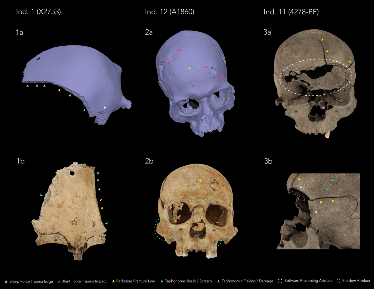
Figure 1
3D modelling of sharp- and blunt-force trauma injuries in the ‘Body-Objects’ digital imaging dataset generated with Agisoft Metashape: (1a) Ectocranial view of Individual 1 in solid mode; (1b) Endocranial view of Individual 1 in textured mode, showing a discrete area of shadow artefact [green dashed circle]; (2a) Superoanterior view of cranium of Individual 12 in solid mode, revealing an additional blunt-force trauma injury [red arrows]; (2b) Frontal view of Individual 12 in textured mode, highlighting areas of shadow artefacts [green dashed circles]; (3a) Frontal view of cranium of Individual 11 in textured mode, demonstrating a large software processing artefact [white dashed circle] resulting from a lack of information leading to loss of texture on the 3D model; (3b) Lateral view of left orbital and frontotemporal region of Individual 11 in textured view (figure by E. Tollefsen).
RTI modelling proved particularly useful in instances where taphonomic weathering, discolouration, flaking of the cortical bone surface and/or depositional damage was obscuring smaller and shallow injuries (Figure 2), such as in the case of Individual 4 and Individual 11. When assessing Individual 1, specular enhancement and diffuse grain transformations (i.e. rendering modes) together with further manipulations of the light source in RTIViewer helped distinguish the sharp-force injury impact site on the posterior parietal from the postmortem break edge running anteriorly towards the right supraorbital region – identified as a possible taphonomic stress fracture, likely originating along a radiating facture line resulting from the original traumatic injury.
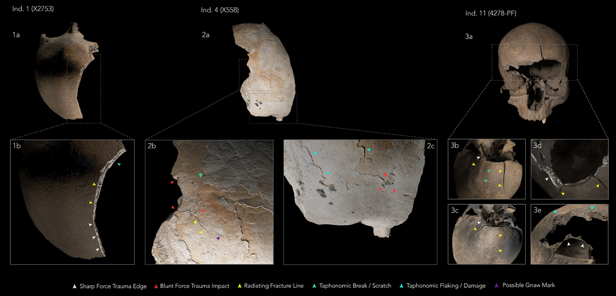
Figure 2
RTI modelling of sharp- and blunt-force trauma injuries in the ‘Body-Objects’ digital imaging dataset using PTM18(*) and HSH27(**) models generated with RTIViewer: (1a) Superoposterior view of cranium of Individual 1 under Default view**; (1b) Superolateral view of Individual 1 using Specular Enhancement mode**; (2a) Superior view of cranium of Individual 4 under Default view**; (2b) Close-up of lateral portion of frontal using Coefficient Unsharp Masking mode*; (2c) Close-up of anterior portion of frontal using Dynamic Multi Light mode*; (3a) Anterior view of cranium of Individual 11; (3b) Superior view of anterior portion of frontal using Coefficient Unsharp Masking mode*; (3c) Superior view of anterior portion of frontal using Diffuse Grain mode*; (3d) Superior view of left orbit using Specular Enhancement mode*; (3e) Anteroinferior view of right orbit using Coefficient Unsharp Masking mode* (figure by E. Tollefsen).
Spatial coverage
Description: The remains making up the ‘Body-Objects’ digital imaging dataset were analysed by the BODY-POLITICS project between September 2023 and June 2024 in the respective collections of the following museums and institutions across Denmark: The Historical Museum of Northern Jutland, Aalborg, North Jutland Region; Moesgaard Museum, Aarhus, Mid Jutland Region; and the Department of Forensic Anthropology, University of Copenhagen, Copenhagen, Zealand.
Northern boundary: Lat. 57.0153517641358, Long. 10.0026481315609
Southern boundary: Lat. 55.5136516539217, Long. 10.3824469536739
Eastern boundary: Lat. 55.6167267315412, Long. 11.9607901969815
Western boundary: Lat. 57.0153517641358, Long. 10.0026481315609
Temporal coverage
c. 500 BCE – 1050 CE (see Table 1 for new AMS dates obtained by BODY-POLITICS).
(2) Methods
Identification of Skeletal Trauma
Skeletal trauma was identified within the dataset by visually evaluating the following:
If partial or complete break in the continuity of a bone was observed — trauma was identified as fracture.
If fracture presented as round or oval depressions, particularly on the cranial vault (direct impacts) or fracture margins showed signs of compression, tension, torsion and/or shearing (indirect impacts) — fracture was identified as blunt-force trauma
If fracture presented as clean incisions with well-defined margins and a smooth surface — fracture was identified as sharp-force trauma
If evidence of healing including bone remodelling and callus formation was observed — trauma was determined to be antemortem.
If a lack of new bone formation and remodelling was observed — trauma was determined to be perimortem.
For further details on the analysis, identification and reporting of the skeletal trauma within this digital imaging dataset, and another 8 individuals, we refer the reader to the linked research article ‘Broken Bodies in Domestic Spaces’ [1] — where we discuss the wider archaeological context of these remains and situate these injuries as indicators of direct and structural violence in Iron and Viking Age Scandinavia.
Sampling strategy
The four sets of remains were selected for digital imaging on the following grounds:
Remains exhibiting trauma or possible trauma that had either been contested or where interpretations were unclear in previous reports.
Remains with instances of trauma where macroscopic assessment required expansion, and the utility of 3D photogrammetric models and RTI models was determined to be of specific practical use.
Access and permission given by the collection holders, and logistical concerns (including travel cost, time and facilities required for image acquisition and processing).
Steps
Photogrammetry
Photogrammetry is a computer-based technique whereby overlapping 2D data of the same object captured using image sources (e.g., photography, video) are imported into a dedicated software (Agisoft Metashape) to generate 3D data (i.e. 3D models). Due to its non-invasive nature and high accuracy, photogrammetry is becoming a preferred digital documentation method in the study and conservation of skeletal human remains in various states of preservation and completeness, including the reconstruction of skeletal trauma [e.g. 9, 10, 14, 15].
The skeletal elements exhibiting violence related injuries from the selected remains were mounted on a white turntable in front of a white backdrop, and portable LED spotlights were used to illuminate the area of interest and to minimise any shadows across the bones. A series of high quality RAW and .JPEG photographs were taken by E. Tollefsen (ET) using a Canon EOS 2000D DSLR camera, a remote shutter trigger and a tripod – ensuring a at minimum 50%+ overlap of the object per image capture.
Once obtained, the images were imported into the Agisoft Metashape software by V. Louka (VL). The quality of the images was calculated using the ‘Estimate Image Quality’ tool, and any images with suboptimal quality were removed (i.e. images below 0.5–0.6 units, e.g. due to blurring, over- or under-exposure). The remaining images were aligned to obtain the initial sparse cloud which was further processed to remove unnecessary points and areas (e.g. the background and artefact). Lastly, the dense cloud was built, and the final mesh was generated; after which the texture was applied to produce the finished, textured 3D model. See Table 2 for overview of Agisoft Metashape settings used at each stage of generating the photogrammetric models within the dataset.
The files generated using Agisoft Metashape were exported as 3D objects in two forms: Wavefront OBJ (.obj) and Polygon File Format (.ply). For the PLY files, the accompanying texture was saved in a Joint Photographic Export Group (JPEG) format (.jpg). The OBJ files were accompanied by both JPEG and Material Template Library (.mtl) files, with the latter defining details such as surface shading and material properties for geometry of the reconstructed object.
A comparative and contextual study was then conducted by all authors [1], identifying and comparing the observable skeletal trauma by alternating between the solid and textured modes in Agisoft – alongside the various visualisation transformations of the RTI models where applicable – across the selected remains, as well as considering the remains’ deposition context, osteobiographies and the broader archaeological and forensic discourse around trauma analysis, to facilitate interpretation of the violence related injuries.
Table 2
Overview of image counts and Agisoft Metashape workflow settings used during generation of photogrammetric models within dataset.
| INDIVIDUAL NUMBER | FIND ID | TOTAL NUMBER OF IMAGES | NUMBER OF FACES | NUMBER OF TIE POINTS | ACCURACY SETTING | ANY EXTERNAL CONTROL POINTS? |
|---|---|---|---|---|---|---|
| 1 | X2753 | 257 | 176 522 | 88 582 | High | No. |
| 11 | 4278-PF | 368 | 659 782 | 204 317 | High | No. |
| 12 | A1860 | 319 | 3 094 642 | 173 283 | High | No. |
The operational system used for photogrammetry was a HP Z4 G4 Workstation (x64-based PC), with Intel(R) Core(TM), i9-7900X CPU @ 3.30Mhz (10 Core(s), 20 Logical Processor(s).
Reflectance Transformation Imaging (RTI)
RTI captures surface topography through variably lighted photography using an independent light source positioned at different angles and computational processing to reveal surface details at enhanced visibility, capturing three-dimensional reflectance properties of object surfaces [16]. Photographic images captured utilising this technique are processed to create a 2.5D interactive image (RTI model), allowing for a more detailed examination and analysis of subtle colour and surface alterations such as e.g. tool impressions, decoration, taphonomy, handling and trauma traces on bone [17, 18].
RTI capture: 50–100 images per object were captured with a Canon EOS 2000D DSLR camera fitted with an EF-S 18–55 mm IS II lens by ET. The camera settings were adjusted for each set of remains (see Table 1 and 2 of SM2 in [1]), with the ISO consistently set to 100 in order to minimize grain, and the smallest aperture used to maximise the Depth of Field (DoF). We used a setup consisting of a tripod and a Hahnel Modus 360RT flashgun connected to the camera through remote flash and shutter triggers, black marble spheres, and a scale-card, following Cultural Heritage Imaging guidelines [16].
RTI image processing: Image processing was performed using the Open Access programme RelightLab2024.11 software for Mac OS [19]. At the photography stage, images were saved in JPEG and RAW format. Only the JPEG format images were imported into RelightLab for image processing. During processing, the spheres were isolated one at a time, and the highlights reflected from the spheres were detected using the ‘Find highlights’ function. Any image that was either under- or over-exposed, or where the programme failed to detect one or both reflective highlights from the spheres, was excluded when building the individual RTI models.
RTI model creation: Following recommendations by Clarke and Christensen [18], two different models were generated in RelightLab for each area of interest for the various remains: (1) a Polinomial texture map (PTM 18), and (2) a Hemispherical harmonics RTI model (HSH 27). This allowed for the utilisation of a variety of rendering modes in the RTIViewer software. We have found 5 transformations of the reflectance function (i.e. render modes) particularly useful in the current study: default view; specular enhancement; diffuse grain; coefficient unsharp masking; and dynamic multi light (further details on how we utilised the various render modes for trauma visualisation can be found in SM2 in [1]).
A comparative and contextual study was then conducted by all authors [1], identifying and comparing the observable skeletal trauma by alternating between the solid and textured modes in Agisoft – alongside the various visualisation transformations of the RTI models where applicable – across the selected remains, as well as considering the remains’ deposition context, osteobiographies and the broader archaeological and forensic discourse around trauma analysis, to facilitate interpretation of the violence related injuries.
Quality Control
All handling of the remains in connection with the analyses was done following professional guidelines [20, 21] and with the use of nitrile gloves to protect the remains.
Photography Stage
The highest-quality simultaneous RAW and JPEG capture setting was selected on the Canon EOS 2000D DSLR camera for the photographic stages of both photogrammetry and Reflectance Transformation Imaging (RTI). This approach ensured that high-resolution JPEG files were produced directly during image acquisition, providing detailed and high-fidelity imagery suitable for subsequent processing. The availability of JPEG files was particularly important for the downstream processing workflows, as both Agisoft Metashape and Relight software utilised JPEG images for photogrammetric reconstruction and RTI processing, respectively. Simultaneous RAW and JPEG capture therefore eliminated the need for a separate RAW-to-JPEF conversion stage, streamlining the workflow whilst retaining the original RAW files as a lossless source for archival purposes and potential future processing.
Photogrammetry Workflow
The quality of the images was ensured by following a three-step process: Firstly, the lighting conditions and minimising of shadows were controlled during the photography stage. Secondly, once the images were imported into Agisoft Metashape, and before any processing, they were visually assessed for signs of blur, over- or underexposed areas and, where possible, these images were eliminated. Lastly, the quality of the remaining image set was calculated using the ‘Estimate Image Quality’ software tool and, depending on the model, any images with quality lower than 0.5–0.6 units were removed.
Reflectance Transformation Imaging Workflow
Image quality was ensured by following a two-step process: Firstly, at the photography stage any issues with potential blurriness was controlled by slowing down the movement of the remote handheld flash and avoiding any rapid movements when releasing the remote shutter. Secondly, during image processing in RelightLab, any image that was either under- or over-exposed, or where the programme failed to detect one or both reflective highlights from the spheres, was excluded when building the RTI models.
Constraints
Artefact issues and 3D models: Overall, the photogrammetry produced high-quality models with clear and detailed texture, yet some artefacts were observed. The 3D models for Individual 11 and Individual 12 were generated with some artefacts which were visible on the interior surface of the respective 3D crania. The artefacts emerged in two distinct forms: (a) dark areas, and (b) as a lack of information and, therefore, texture. The first artefact (a) resulted from natural shadows cast by surrounding structures during photography, which become reconstructed as dark-coloured areas (as seen in the inputted images); whereas the second artefact (b) showed up as the exterior surface of the model being visible from the inside due to the ‘lack of information’ in those areas. This is a result of insufficient lighting in specific areas during photography, or areas that do not have sufficient point coverage. This is a known phenomenon that can occur during photogrammetry when Agisoft Metashape does not have the ability to reconstruct visual information that is missing and/or underrepresented in the photographs. When this occurs, the software can only reconstruct features where the corresponding information – in the form of points – is available from the inputted images. However, it must be highlighted that covering defects and natural cavities is challenging in photogrammetry. Furthermore, digitisation of specific structures and coverage also relies on the scope of the project, which in this case, was the reinforcement of skeletal analysis. In the selected individuals, the artefacts did not interfere with the overall quality of the 3D model or the injuries in question.
Agisoft Metashape Troubleshooting: The correct course of action during issues in photogrammetry is software and workflow troubleshooting. However, in cases where the artefacts are the result of image quality, the solution lies in re-capturing the images for the problematic area by adjusting the object and correcting the lighting conditions. In our case, due to the collation of photographs for photogrammetry at a later time, returning to the skeletal collections was not feasible.
Challenges with RTI modelling: when photographing the extensive violence related injuries to the facial region of Individual 11, we noted challenges in capturing the entirety of the trauma in sharp focus across the anterior cranium. Due to the variation in the topography of the facial bones, not all features or the totality of the violence related injuries will be in-focus once the camera is set to manual focus. This introduced some blurry artefact to the model once the captured images were processed in RelightLab. However, clarity of specific areas of interest in the orbital region made insightful observations possible. This has provided a significant learning experience and one which can be applied to future RTI capture, particularly when the objects under study are topographically complex. As a consequence, if such a process were to be repeated on the facial region of crania or similar objects, we would recommend that steps are taken within the methodology to divide the area of interest into smaller zones to mitigate for contour topography issues.
Software: Accessibility and Maintenance
We are mindful that Agisoft Metashape is a commercial, proprietary programme, its cost and licensing requirements may limit its accessibility and suitability for some researchers. The following free and open-source alternatives provide viable options for photogrammetric processing and 3D model generation, while offering different levels of accessibility, control and technical capability. (i) AliceVision Meshroom provides a user-friendly, node-based workflow for generating visually accurate 3D models suitable for documentation, visualisation and analytical purposes [22]. (ii) COLMAP offers general-purpose Structure from Motion (SfM) and Multi-View Stereo (MVS) pipelines, providing greater control over photogrammetric processing and supporting more reproducible research workflows [23]. However, its greater level of configurability also makes it more technically demanding than Meshroom. (iii) MicMac is a highly capable photogrammetric package that is similarly more technically advanced, but offers extensive functionality for metric photogrammetry and research-oriented applications [24]; (iv) RealityScan is a commercial, proprietary photogrammetry platform that is currently available free of charge to students, educators and educational institutions, and offers an intuitive interface and automated processing workflow for users with limited specialist expertise [25].
The most up-to-date and advanced processing and calibration software for Reflectance Transformation Imaging (RTI) is the open-source Relight programme, which supports the use of Polinomial Texture Mapping (PTM), Hemispherical Harmonics (HSH), as well as newer Principal Component Analysis (PCA) and Radial Basis Function (RBF) based algorithms [19]. Relight officially replaced earlier tools such as RTIbuilder and is freely available to download from the Visual Computing Lab [19]. Additional software, in the form of the RTIViewer programme, is required to view and manipulate the resulting relightable images. RTIViewer is also open-source and freely available to download from Cultural Heritage Imaging [17]. Cultural Heritage Imaging also provides a clear and concise guide to using RTIViewer: ‘RTIViewer User Guide 1.1’.
(3) Dataset description
Object name
Dataset A (Photogrammetry of selected skeletal trauma from Iron and Viking-Age Scandinavia: A BODY-POLITICS dataset) and Dataset B (Reflectance Transformation Imaging of selected skeletal trauma from Iron and Viking-Age Scandinavia: A BODY-POLITICS dataset) are stored in the EU Open Research Repository on the EU Open Access server Zenodo.
The data consist of three photogrammetric models and seven RTI files, in the following formats: Photogrammetry dataset.zip (3 .obj / 3 .ply / 3 .jpeg / 3 .mtl files as 3 .zip files); and RTI models.zip (7.rti files).
Data type
Primary data processed as digital imaging models.
Format names and versions
.OBJ, .PLY, .JPEG, .MTL, .ZIP, .RTI
Creation dates
September 2023 – June 2024
Dataset Creators
The dataset was initiated, created, and funded by the BODY-POLITICS project, PI Professor Marianne Hem Eriksen. Dr Emma Tollefsen captured and collated all photographs and generated the RTI models. Dr Vasiliki Louka generated the photogrammetric models. The RTI capture protocol is based on a workshop co-organized by the BODY-POLITICS project and The Research Centre of Material Worlds Past and Present, both at the University of Leicester, held by Dr Marta Diaz-Guardamino, University of Durham. Further guidance on RTI capture was provided by Dr Rachel Crellin, University of Leicester.
Language
English
License
CC-BY 4.0
Repository location
Zenodo repository latest versions:
https://doi.org/10.5281/zenodo.18803569 (Dataset A);
https://doi.org/10.5281/zenodo.18851656 (Dataset B).
Publication date
3 March, 2026
(4) Reuse potential
The datasets of 3D and RTI models of human remains offer reuse across multiple possible areas, including osteoarchaeology, forensic anthropology, education, and public outreach.
In osteoarchaeological and forensic anthropological research, high-quality three-dimensional photogrammetric models can enhance the visualisation of surface features and enable the reconstruction and digital analysis of human remains, including the digital measurement of skeletal trauma [26] – without the risk of damaging the remains from repeated handling. Obtaining accurate measurements of skeletal trauma can be challenging on the original remains due to factors such as restricted access to affected areas, fragile or fragmented bones, and irregular surface morphology. Digitally reconstructed models may overcome some of these limitations by providing detailed and measurable representations of the remains without the need of further manipulation of the original specimen.
Osteological features, taphonomic details, violence related injuries and other trauma in remains curated in multiple collections and locations can therefore be studied – helping to facilitate collaboration across national borders and reducing associated research costs related to travel and institutional fees, ultimately making skeletal collections more accessible and equitable.
For archaeologists, the dataset herein offers information and documentation of violence related injuries from Scandinavian later prehistory, including in periods famous for violent altercations [5, 27, 28, 29, 30, 31, 32, e.g. 33]. The models may also aid in further macro- and microscopic analyses, as well as taphonomic studies.
Furthermore, digitisation of human remains ensures posterity and the creation of a permanent, controlled digital record which can be ethically used, where possible, for digital exhibitions and teaching. Digital models can increase public engagement with and appreciation of bioarchaeology and the people of the past [e.g. 34, 35, 36, 37 and refs therein]. Physical replicas can be printed for outreach or teaching purposes using 3D printers, offering tactile, interactive examination. The digital clones are also useful as a method of documentation in cases where human remains need to undergo destructive analyses such as isotopic analysis, histology and radiocarbon dating.
Acknowledgements
We warmly thank the following people and institutions for facilitating data collection and analysis: Niels Haue, Historical Museum of Northern Jutland; Trine Kellberg Nielsen, Moesgaard Museum; Dr Mogens Bo Henriksen, Museum Odense; Ole Kastholm, Roskilde Museum; and Dr Marie Louise Schellerup Jørkov, the Globe Institute/Copenhagen University; Dr Jo Appleby, Dr Sarah Inskip, and Dr Veronica Tamorri, University of Leicester. We also thank University of Leicester Archaeological Services for granting access to use their facilities for photogrammetry processing. We are very grateful to Marta Díaz-Guardamino, University of Durham, and Dr Rachel Crellin, University of Leicester, for RTI training and advice.
Author Contributions
Conceptualization: MHE, Formal analysis: all authors, Funding acquisition: MHE, Writing-original draft: all authors, Writing-review and editing: all authors.