
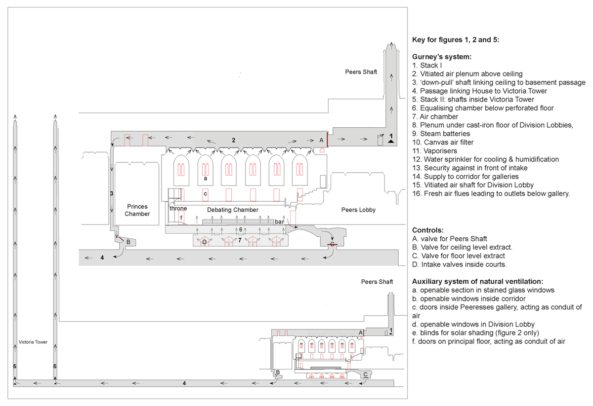
Figure 1
Houses of Parliament: diagrammatic cross-section showing the stack ventilation system with control valves.
Source: Author’s own drawing.
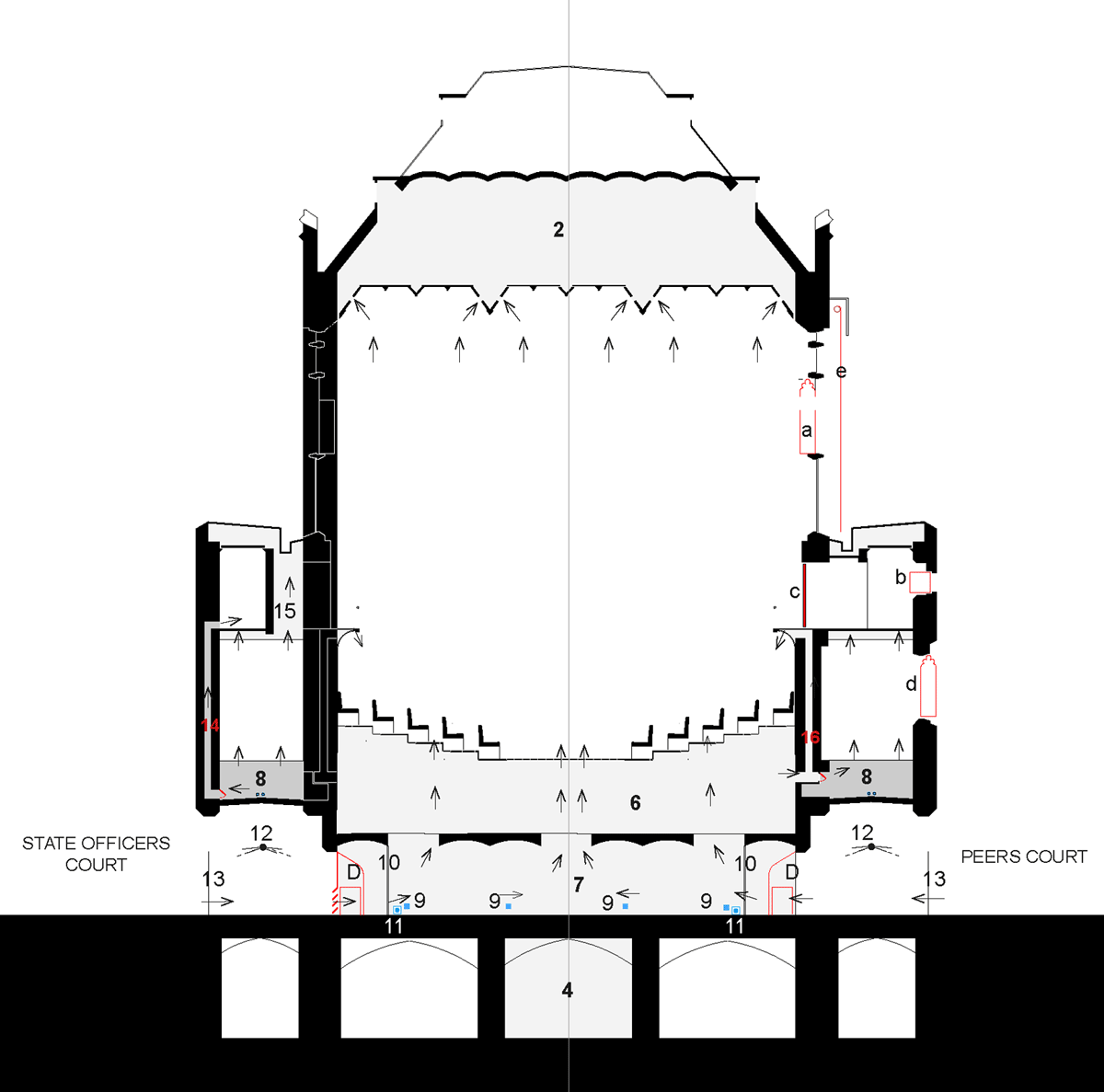
Figure 2
Cross-section showing features of the environmental system.
Source: Author’s own drawing.
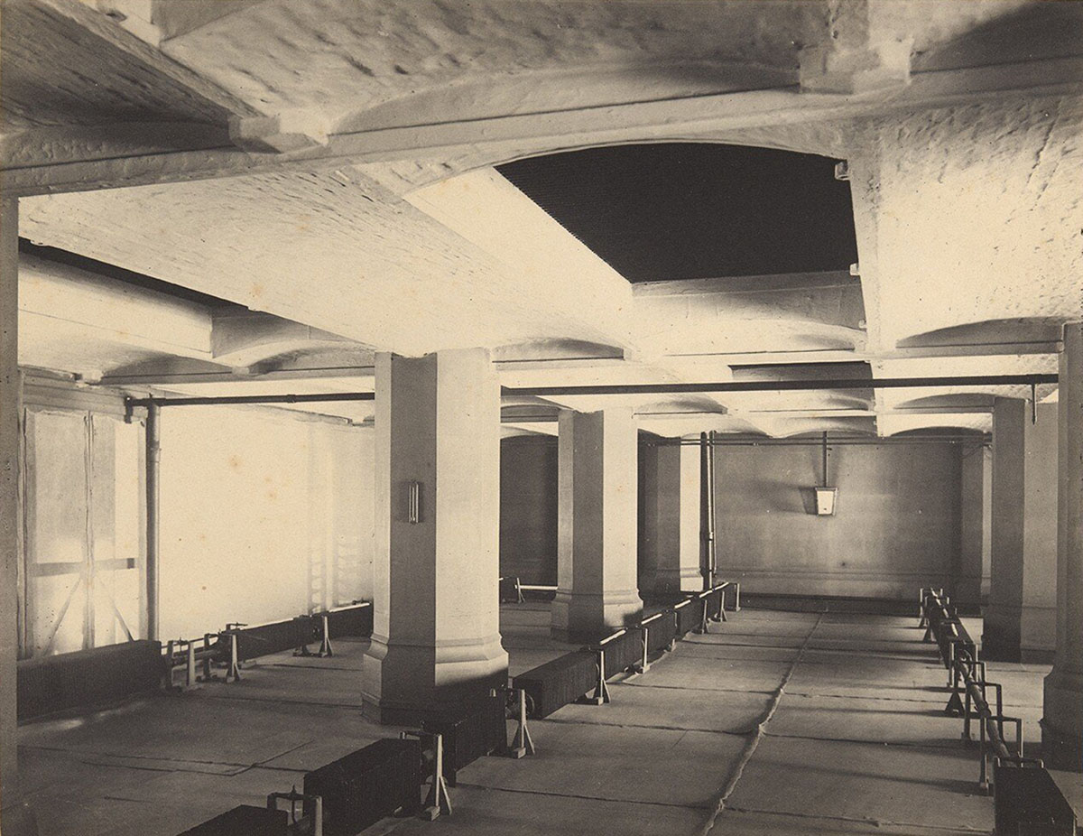
Figure 3
Interior of the air chamber, July 1897, showing canvas screens (left), three rows of heating batteries and apertures to the equalising chamber above.
Source: Stone (1897b: photo. 19).
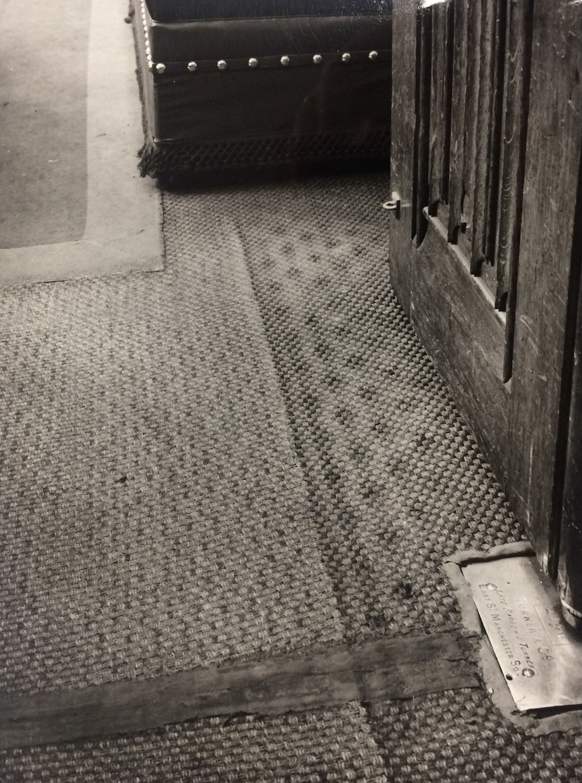
Figure 4
Floor composed of iron gratings and a perforated timber panel below a layer of sisal matting.
Source: Ministry of Public Building and Works (1966).
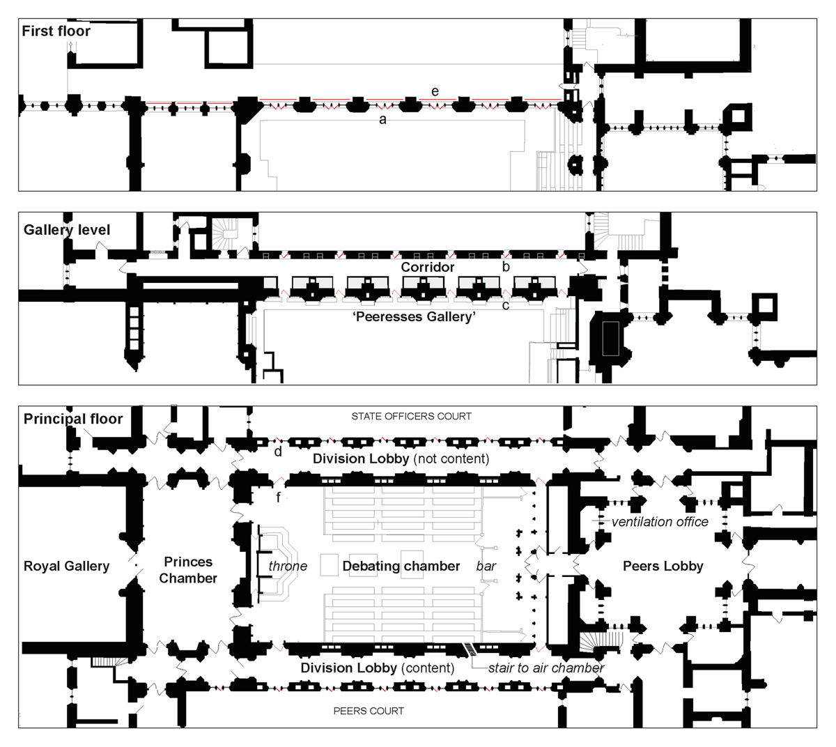
Figure 5
Floor plan of the House of Lords.
Source: Author’s own drawing.
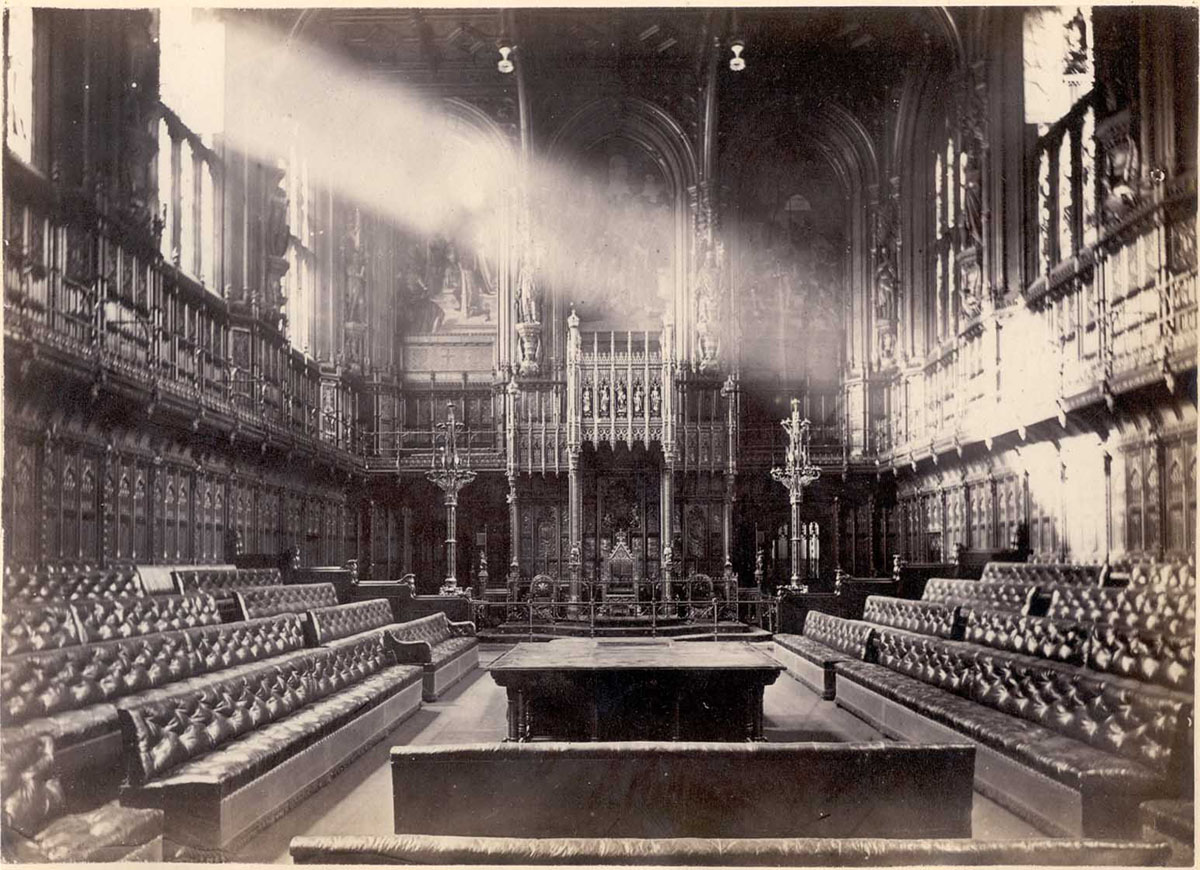
Figure 6
Open windows inside the Lords Chamber, 1869.
Source: Harrington (1869: pl. iv).
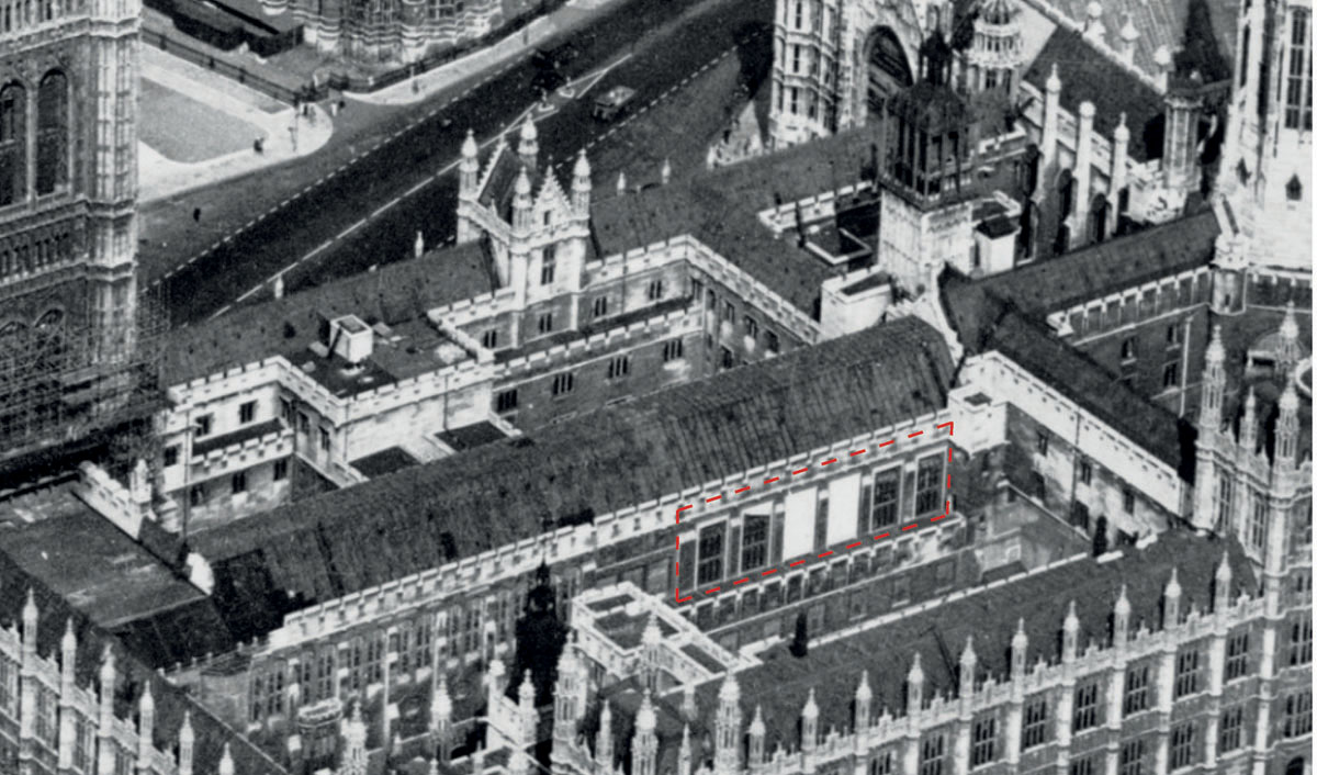
Figure 7
Aerial photograph, January 1948, showing the external shading reinstated after the war.
Source: Historic England Archives, photo. OP17839.
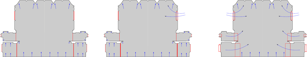
Figure 8
Three operational modes.
Key: Left: Mode 1: Sealed and served by stack ventilation; Centre: Mode 2: Stack ventilation with supplementary natural ventilation; Right: ‘Mode 3: Mostly natural ventilation.
Source: Author’s own drawing.
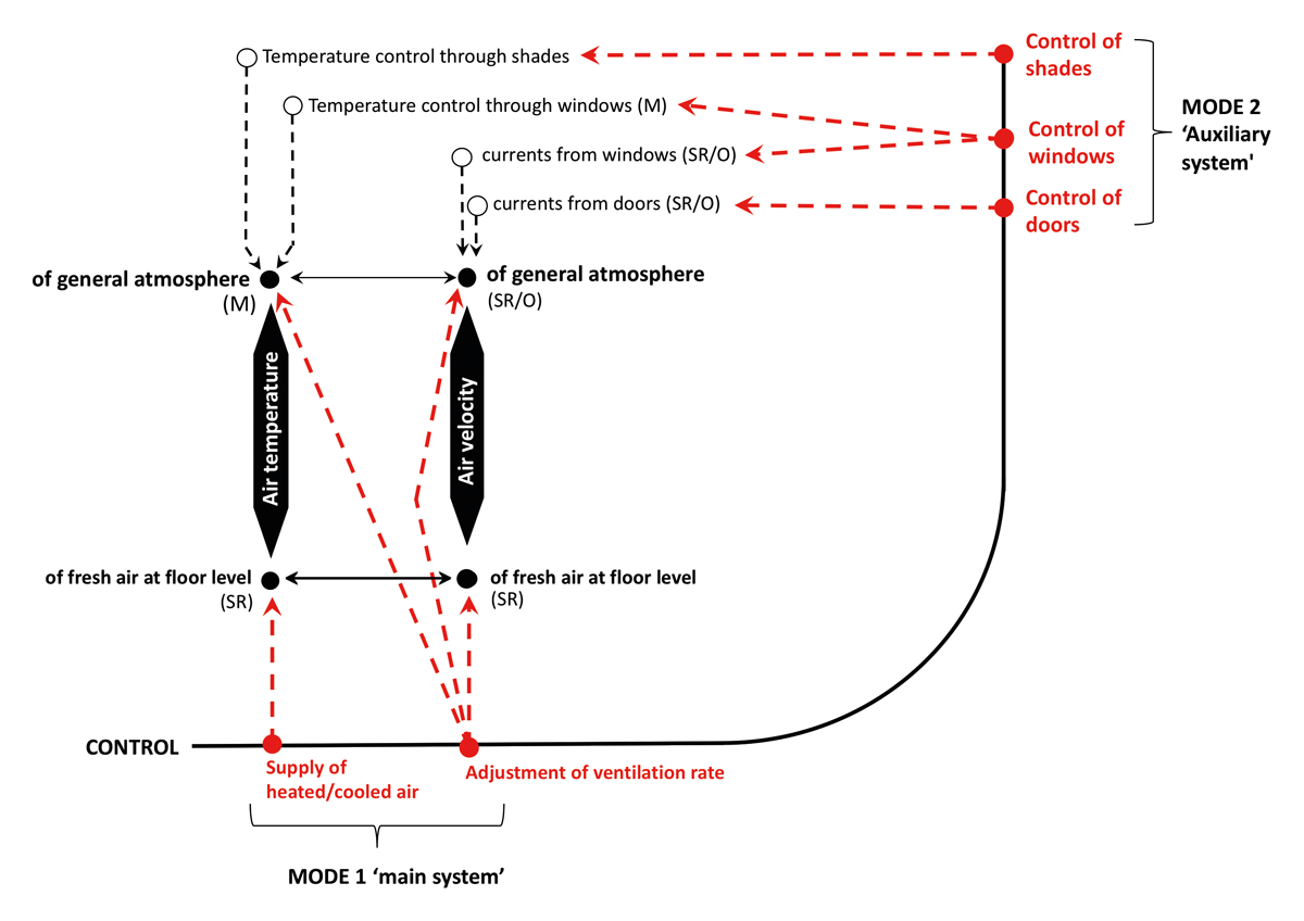
Figure 9
Socio-technical control and feedback system.
Note: M = measurements; O = direct observation by staff and officials; and SR = user feedback.
Source: Author’s own drawing.
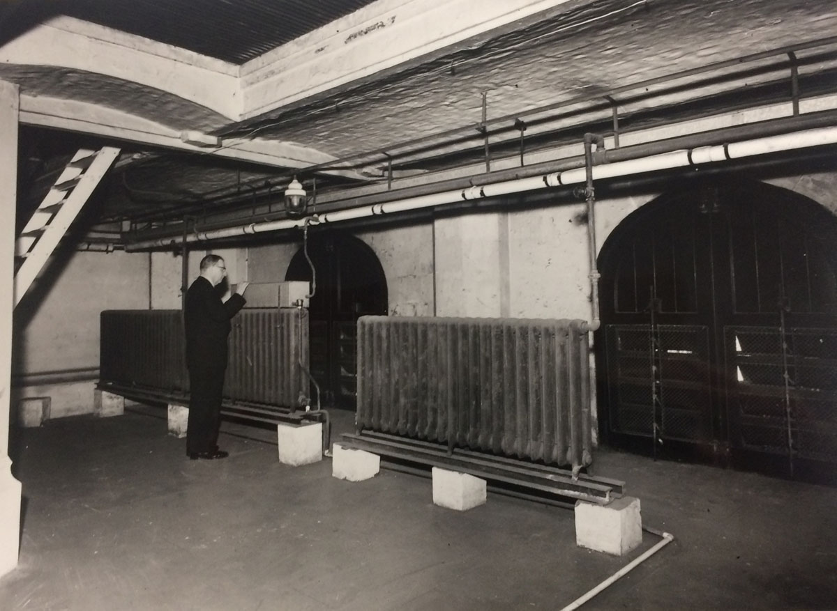
Figure 10
Interior of the air chamber, 4 March 1966, showing the adjustable louvres of the intakes.
Source: Ministry of Public Building and Works (1966).
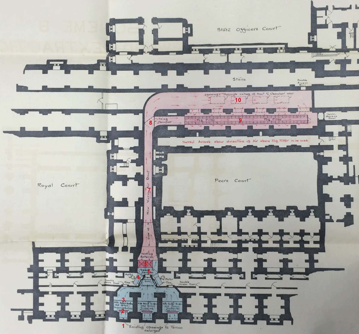
Figure 11
Floor plan of the scheme for new air intake, 1912.
Note: 1 = Intakes on the terrace; 2 = tempering radiator; 3 = wire gauze filters and water sprayers; 4 = fans; 5 = heating batteries; 6 = damper to switch between cold air (bypass) and the heating mode; 7 = air passage; 8 = damper to divert the supply to the fog filter during heavy smog; 9 = fog filter (during heavy smog only); 10 = valves for supply to the chamber above; blue = cold air; and pink = warm air.
Source: Patey (1912a).
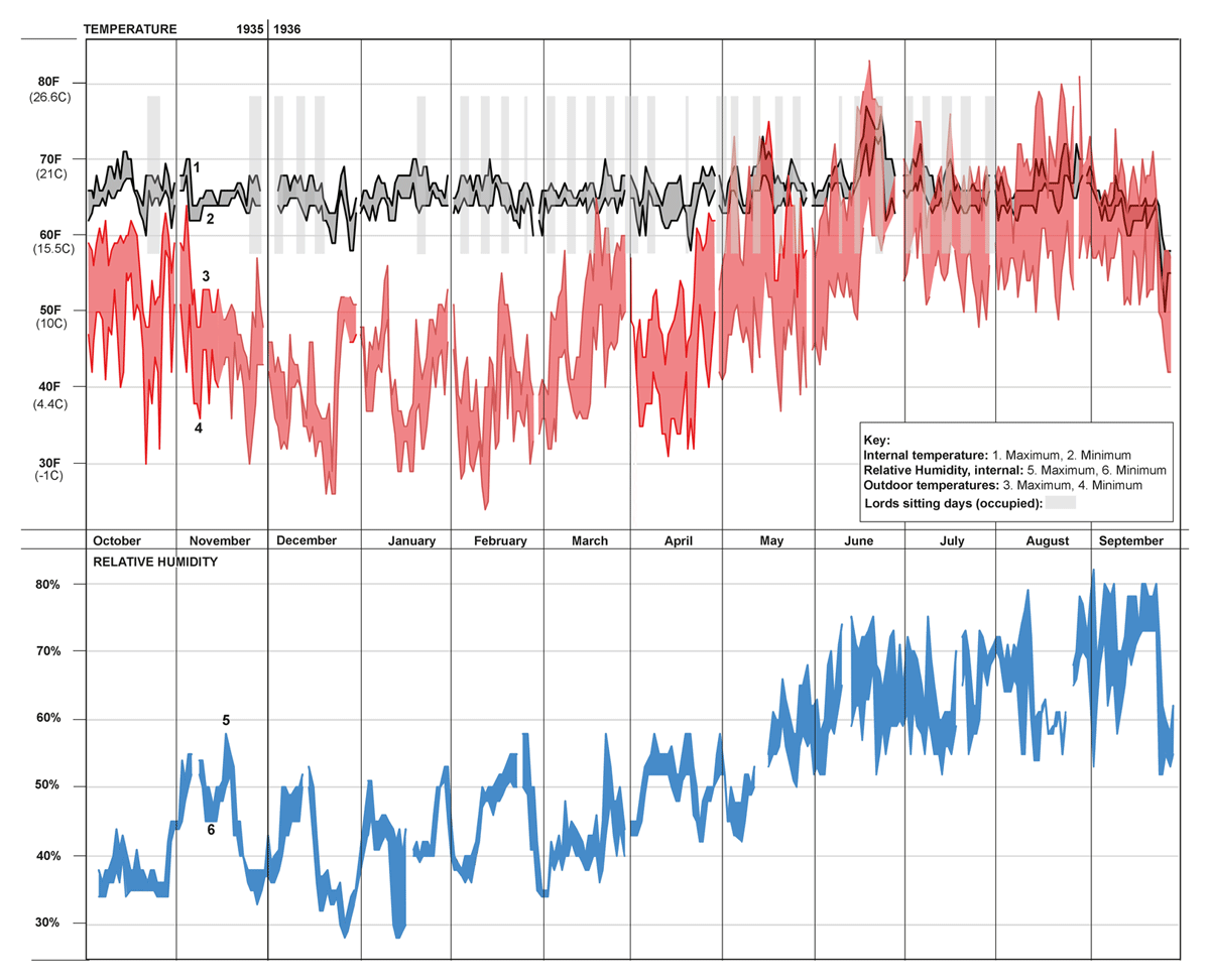
Figure 12
Temperature and humidity recorded inside the House of Lords, October 1935 and September 1936.
Source: Author’s own drawing.
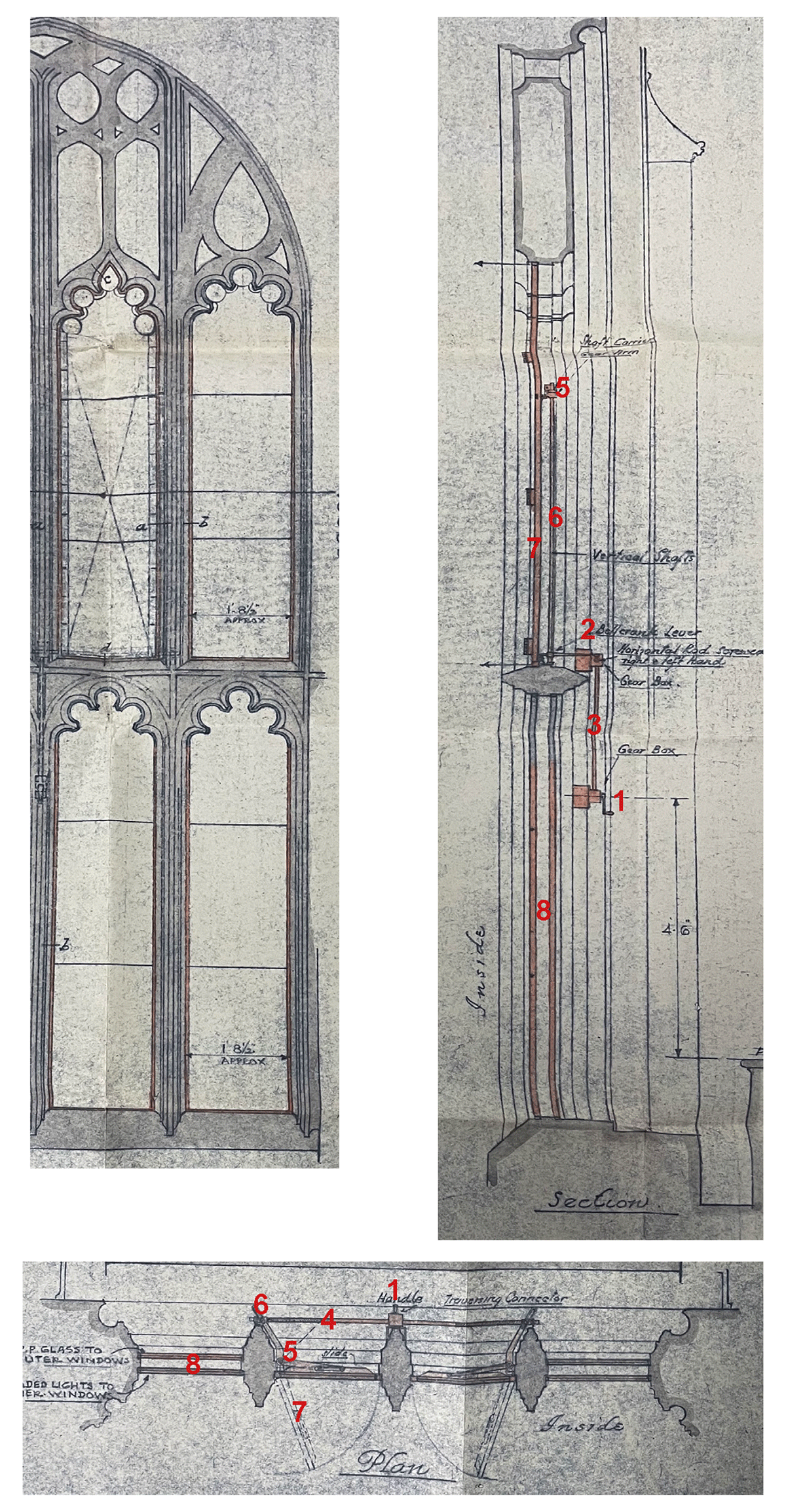
Figure 13
Details of windows with operating gear, 20 October 1943.
Note: 1 = Hand-operated gear on the exterior with a handle; 2 = upper boxes; 3 = vertical rod linking the hand-operated gear to the upper gearbox; 4 = horizontal rod linking the upper gearbox to the levers of two openable casements; 5 = levers; 6 = vertical rod linking the bottom and top levers of the casements; 7 = openable casement; and 8 = two layers of fixed glazing with stained glass internally and plain glass externally.
Source: National Archives, Work 11 Series, Box 443.
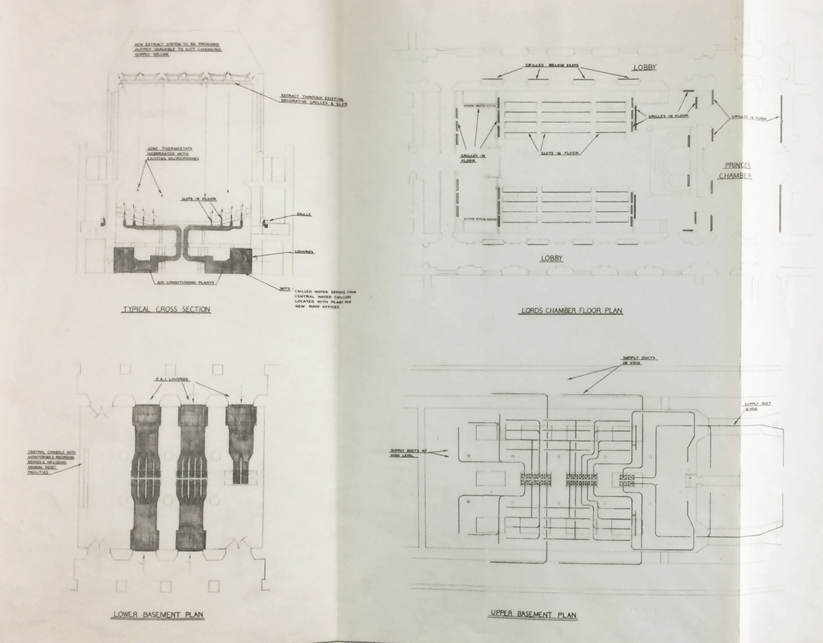
Figure 14
Proposed air-conditioning system, November 1963, show ductwork and the configuration of floor grills.
Source: National Archives, Work 11 Series, Box 588.
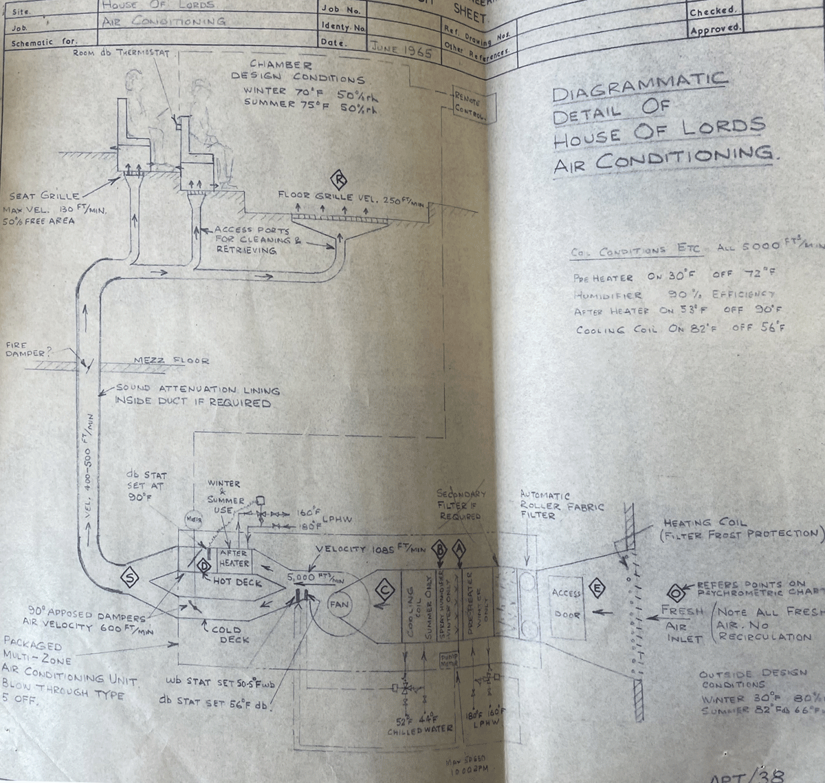
Figure 15
Sketch of the mock-up system, June 1965.
Source: Ministry of Public Building and Works (1965).