
1. Introduction
Scoliosis is one of the most common spine disorders in children and youth aged 3–18 years and remains a major challenge in modern orthopaedics. Spinal deformities affect 2–3% of the population, with early childhood scoliosis affecting about 1% (ca. 1.9 million children) [1,2]. Spine disorders may result from congenital anomalies in vertebral, nervous, or muscular system development (non-idiopathic scoliosis). Over 10–15% of patients are diagnosed with adolescent scoliosis of unknown aetiology (idiopathic scoliosis); rapid progression may lead to cardiac and pulmonary disorders and, in over 95% of cases, requires surgery [1,3].
The most common method of spinal stabilization used to correct scoliosis in children is posterior transpedicular fixation. In this technique, pedicle screws and rods are inserted to reposition vertebrae and stabilize the affected spinal segment. The disadvantage of this system is markedly restricted mobility, which hinders growth in the stabilized section and often leads to staged treatment with repeated surgical lengthening during the child’s growth [4,5].
Growth-guidance systems (GGSs) for spinal stabilization are now available and, among other advantages, reduce the need for multiple surgeries while enabling control of deformity correction during growth (Shilla growth-guidance system, Luque trolley, magnetically controlled growing rods (MCGR), and spring distraction system). Some conventional GGSs, as well as vertical expandable prosthetic titanium rib devices, still require regular surgical distraction, which increases the burden for young patients [6]. This problem was partly addressed by MCGR, but MCGR still shows a high rate of implantation-related complications, requiring revision surgery in ca. 30–50% of patients after 2 years [7,8].
Many of these solutions are based on transpedicular stabilization with kinematic pairs that enable relative sliding of the stabilizer components without surgical intervention [9,10]. However, these systems are not free of defects. Friction between sliding titanium alloy components contributes to generation of wear products that can be deposited in tissues surrounding the expanding joint and form “tissue tattoo”, i.e. regions with a high concentration of released metal particles [9,11,12]. Titanium particles released by fragmentation, friction wear, and corrosion may cause inflammatory conditions and can lead to metallosis, osteolysis, and loosening of the stabilization system.
To prevent/eliminate undesirable effects caused by friction/wear products, solutions are sought using surface engineering methods, to improve functionality of implants. One such method is the application of different types of coatings, including diamond-like carbon (DLC) coating, on components working together and forming a kinematic pair of a screw and a rod, enabling the screw to slide along the rod. DLC coatings represent a unique combination of mechanical and tribological properties, and as they are made of a biocompatible and biologically inert material, they can potentially be used for orthopaedic implants. DLC coatings are widely used in medicine, especially in dentistry and orthopaedics (e.g. knee prostheses), where their main task is actually to eliminate products of tribological wear [13–15]. Due to their low coefficient of friction, high resistance to wear, and biocompatibility, these coatings efficiently reduce the risk of inflammation in tissues surrounding the implant and prolong its life. Furthermore, DLC has antibacterial properties, which is particularly important in the context of its contact with oral microflora or the internal body environment.
The aim of this study is to determine the effect of DLC coating on the mechanical properties of an internal stabilization system modelling the spine during growth. High-cycle compression tests were performed for implant systems without surface modification (standard Ti-6Al-4V construction) and after modification with a DLC layer. To verify whether the stiffness of the proposed solutions was similar to that of the physiological spine, the analysed mechanical parameters of the stabilized and physiological (non-instrumented) systems were compared.
2. Materials and methods
2.1. Sample preparation
Sections of the pig spine (n = 12) at the Th11–L7 level were obtained from the abattoir (age 8–10 months, mean weight 85 ± 10 kg). Soft tissues were removed from the sections, leaving intact the vertebrae, intervertebral discs, ligaments, and joint capsules. Each spine section was stored freshly frozen in a separate package, at −20°C. Before the tests, the sections were thawed for 12 h at room temperature. The sections were not wholly hydrated, because the process of one-time freezing and thawing of fresh sections does not result in their dehydration [16,17] and at the same time, maintaining the intact connection between the intervertebral disc and the adjoining vertebral bodies does not affect the internal structures [18,19]. However, because the prolonged loading was to be applied, external surfaces of soft tissues were secured with gauze soaked with saline solution, to reduce dehydration of external structures both before and during the tests. In addition, intravenous cannulas were inserted into the vertebral bodies at levels L1, L3, and L5, through which a saline drip was administered. This procedure was intended to maintain a constant level of tissue hydration during the planned, long-term stress test.
2.2. Stabilization system
The SOCORE GGS from NovaSpine (Domasław, Poland) for scoliosis correction in children consisted of fixed pedicle screws and polyaxial sliding pedicle screws, rods, and a transverse connector (Figure 1). The sliding pedicle screws used enable movement of the stabilizing system components without a need for surgical interference during the patient’s growth. In the tests, four-segmental stabilization was used (Figure 1a), involving permanent implantation of four central screws, and screws in a sequential system with a sliding cap. In this stabilization system, the structural components can “follow” the growing spine, and at the same time, loads resulting from the scoliotic deformation are transferred. The polyaxial pedicular screw was 6 mm in diameter and 40 mm long, while the rod was 5.5 mm in diameter.
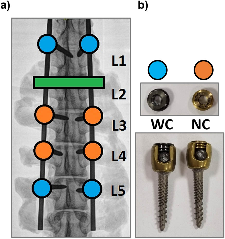
Figure 1
Set for four-segmental stabilization of scoliosis in children SOCORE GGS by NovaSpine: (a) diagram of installation of elements in the Th12-L6 spine segment with transverse connector (green colour); and (b) typical fixed pedicle screw with locking cap (orange colour) and sliding cap of pedicle screw with a gap for the movement of the rod (blue colour) with set (or cap) screw without coatings (NC) and with DLC coatings.
The tests were performed on 12 specimens allocated as shown in Figure 1b. To achieve good adhesion of the DLC coating, surfaces of the stabilizer components underwent electrochemical polishing and sandblasting. The a-C-H(Si) DLC coating was applied by physical vapour deposition (PVD) at 240°C with a CrN interlayer, which additionally increases adhesion to the Ti-6Al-4V alloy surface. The DLC coating thickness was 1,000 nm, while the CrN interlayer thickness was 20 nm. The architecture of the coating system is schematically presented in Figure 2.
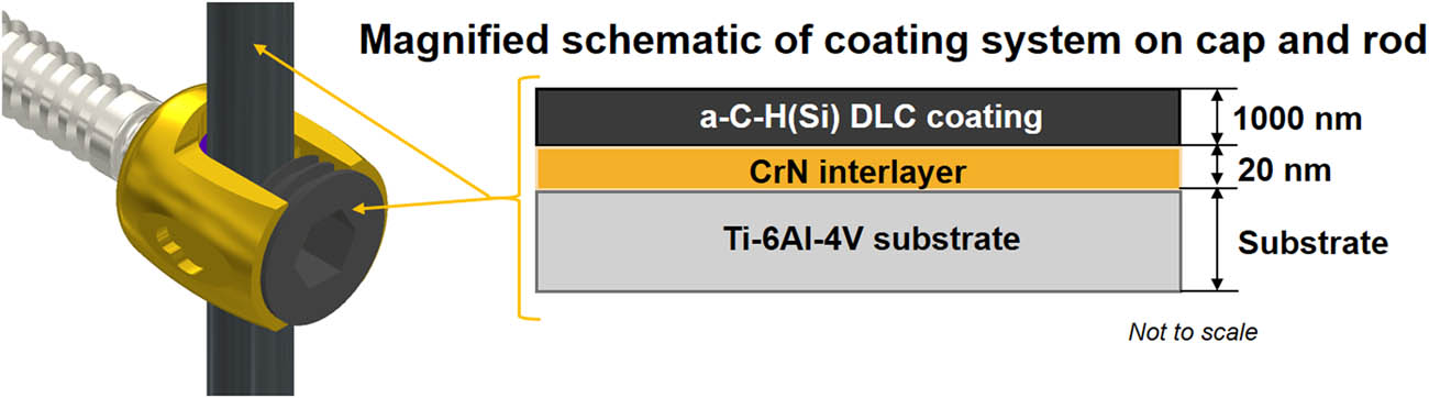
Figure 2
Schematic cross-sectional view of the coated sliding cap (sliding nut) showing the Ti-6Al-4V substrate, CrN interlayer (20 nm), and outer a-C-H(Si) DLC coating (1,000 nm). The layer thicknesses are not shown to scale.
2.3. Cyclic compression test
To analyse the cooperation in the spine and stabilizer system, a prolonged cyclic loading test was performed. The use of cyclic loads was to simulate physiological motions of the spine, in this case, they were mainly associated with axial compression [16,20]. The tests were performed using a system of two clamps specially designed for this purpose, in which extreme vertebral bodies were fixed, installed in rings filled with filling compound (Figure 3a). Simulation of cyclic loads affecting the spine were performed using the machine MTS 858 Mini Bionix® (Leeds, UK). The tests were performed for 100,000 cycles of loading at a frequency of 1.5 Hz, to mimic the frequency of the human gait as far as possible [21]. For axial loads, a force range of 150–650 N ± 10 N was adopted, and this corresponded to the daily range of loads transferred by the lumbar spine of an average adult human, resulting from the weight of their torso, head, and upper limbs [21]. It was assumed that 50 initial cycles correspond to conditioning cycles, and this results from hyperelastic properties of soft tissues, i.e. intervertebral discs and ligaments, and the need to preload them to stabilize the tested spine and stabilizer system.
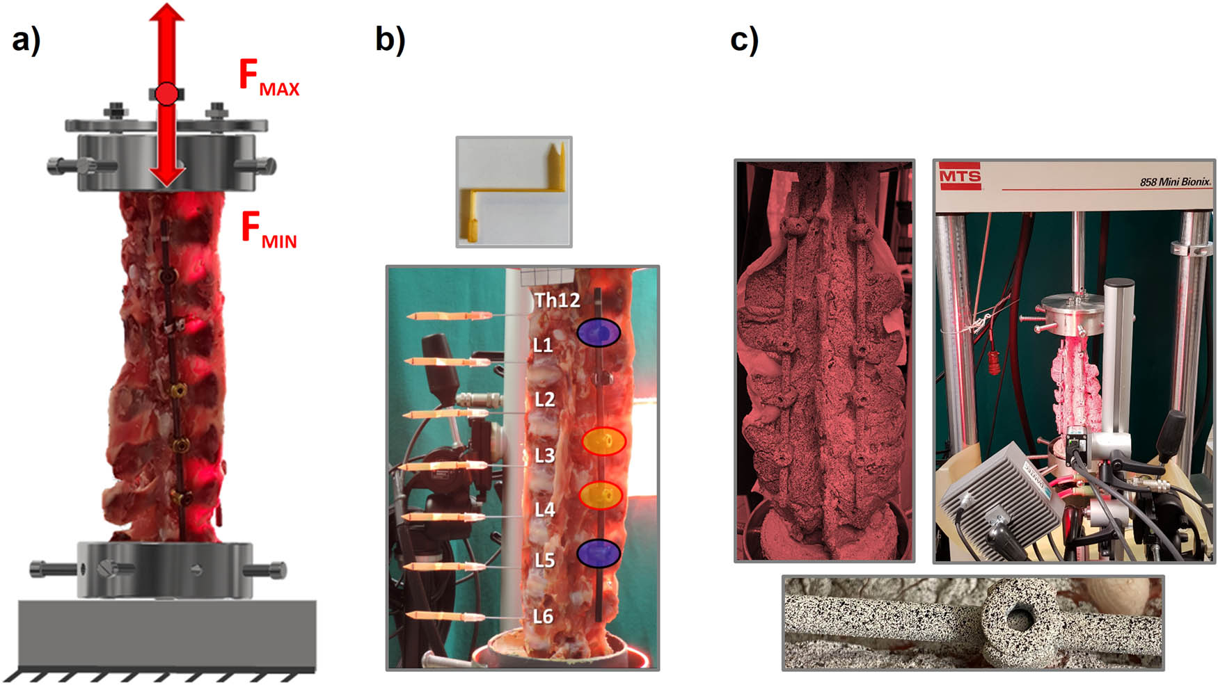
Figure 3
Schematic diagram of: (a) measurement system for high-cycle compression tests; (b) placement of markers in the Th12–L6 vertebral bodies, based on which changes in the angular position of the vertebrae were determined in the sagittal and horizontal planes; and (c) measurement system using digital image correlation with a speckle pattern applied to the implant surfaces.
On the basis of the obtained data, force–displacement characteristics were determined for the tested specimens. For the displacement values obtained at minimum and maximum load, the change in height (H) was established for successive loops. Using displacement in the range from 630 N to the maximum load value of 650 N, the stiffness coefficient (k) was derived.
2.4. Measurement of the range of local vertebral mobility
To describe the kinematics of conditions of edge and resultant loads in the spine stabilizer system, angular displacements and rotation in the horizontal plane were evaluated for individual vertebrae of the tested section of the spine (Figure 3b). The kinematic data were recorded on the basis of displacement of seven markers (rigid body flags) fixed to vertebral bodies at the Th12–L6 level. It was assumed that flags are rigidly fixed to the vertebral bodies during the entire test. The motion of each body during loading with the force of 150–650 N was recorded on the basis of the motion of the rigid body flag. Data were recorded for two ranges of the performed prolonged cyclic load test: initial, for 100 cycles of loading, and end, for 100,000 cycles of loading. Measurements of local mobility of individual vertebrae was performed for all test groups: control (C), stabilization without coatings (NC), and stabilization with DLC coatings (WC). This aimed at determining the effect of the applied layer on the changes in local kinematics of the tested spine stabilizer system.
2.5. Digital image correlation
Real-time determination of the distribution of displacements and strains of the stabilizer components represented an important part of the conducted studies. The tested construction was analysed using Digital 3D Image Correlation System Q-400 from Dantec Dynamics (Skovlunde, Denmark). For the performed measurements, the Digital Image Correlation (DIC) was equipped with two digital cameras and lighting dedicated to the Dantec Dynamics Q-400 DIC measuring system (Figure 3c).
Implant surface preparation was a necessary stage of the measurement. A characteristic and unique pattern was drawn on the surface of the tested implant structures (rods and screws), so the application was able to compare images of spots under load. The spot pattern (light and dark spots) was applied by powder spraying white and black spray paint on the surface of the tested implants (Figure 3c). Before images of the analysed object started to be registered, the cameras had to be calibrated on the unloaded item, using a calibration plate (High-Precision Glass Target, 40 mm Object Size).
On the basis of DIC measurements, distributions of displacement and strain on load-bearing stabilizer components were obtained. The stabilizer area at the L4–L5 segment was analysed, including the sliding pedicle screw in vertebra L5. Mean values and standard deviations were determined for displacement and strain in the kinematic pair formed by the rod and pedicle screw.
2.6. Statistical analysis
All the results obtained from experimental testing were statistically analysed using OriginPro 2025 (OriginLab Corporation, Northampton, MA, USA). The test results were presented as mean values with standard deviations. The statistical analysis was performed on the basis of non-parametric Kruskal-Wallis test, comparing several independent groups at the level of statistical significance of 0.05. The use of logarithmic nonlinear correlation was also assumed for obtained analysed values of a decrease in the height, depending on the number of cycles established on the basis of the correlation coefficient, R. It was assumed that |R| ≥ 0.92 represents a strong correlation.
3. Results
Results from the mechanical test and measurements of local vertebral mobility were analysed for all three test groups (C, NC, and WC). In structural tests and DIC analysis, the focus was on differences between the two instrumented groups: NC and WC.
3.1. Cyclic compression test
On the basis of force–displacement characteristics, a decrease in height (H) was determined for groups C, NC, and WC in successive loops, as shown in Figure 4a. The dynamics of H were similar in all groups and followed a logarithmic decrease (R = 0.96, 0.97, and 0.99 for C, NC, and WC, respectively). Two stages could be distinguished: an initial clear decrease persisting up to 40,000 cycles, followed by a stage in which values remained at a similar level and differences between successive cycles were not significant. The height decrease after 100,000 cycles was 8.76 ± 0.62 mm for NC and 9.32 ± 1.67 mm for WC, corresponding to a 6% difference between the instrumented groups. Compared with C, the difference in height decreases after 100,000 cycles amounted to 19% for NC and 16% for WC.
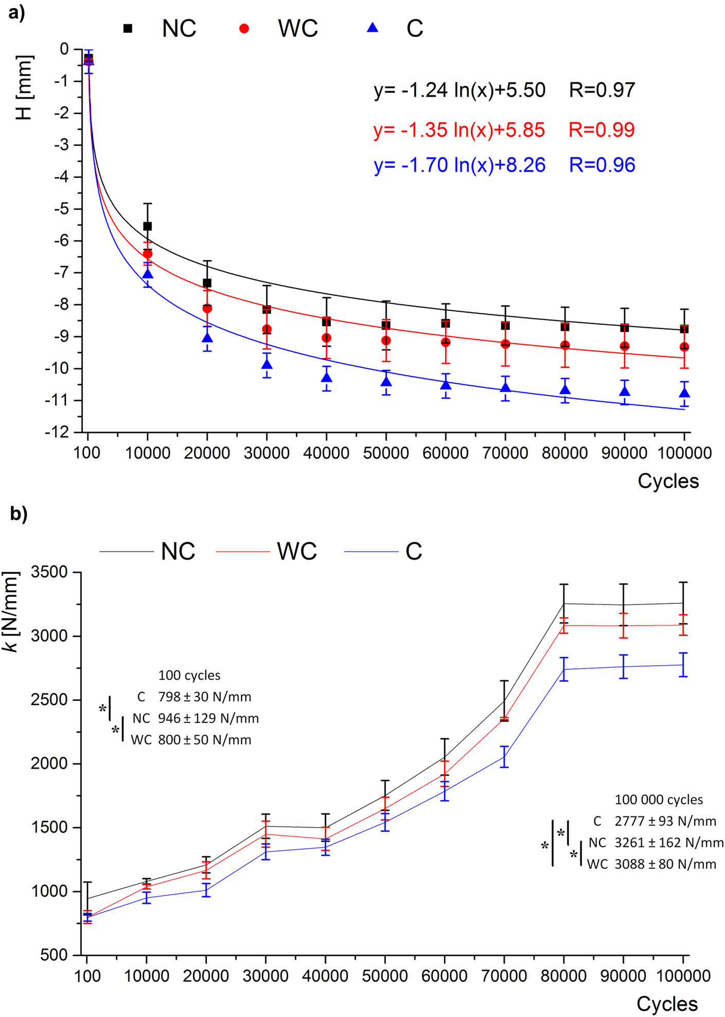
Figure 4
Characteristics: (a) a change in the height value (H); and (b) value of the stiffness coefficient (k) in subsequent cycles for the groups C, NC, and WC. *– Statistical significance (p < 0.05).
The mean stiffness coefficient (k) for the tested groups is shown in Figure 4b. The dynamics of stiffness change were similar and characterized by three stages. After 100 cycles, k was 798 ± 30 N/mm in group C and was statistically significantly lower than in NC (946 ± 129 N/mm), whereas no statistically significant difference was found between C and WC. Initially, k increased, followed by a period of stabilization maintained between 30,000 and 40,000 cycles. At this stage, differences between groups were about 4%. In subsequent cycles, stiffness increased again. From 80,000 cycles onward, no further increase was visible, and k remained at a similar level. After 100,000 cycles, k was 3,261 ± 162 N/mm in NC and was statistically significantly higher than in WC (3,088 ± 80 N/mm; p < 0.05). Thus, DLC coating reduced system stiffness by about 6% relative to the unmodified system. The k value for group C after 100,000 cycles was 2,778 N/mm, i.e. 15% lower than NC and 10% lower than WC.
3.2. Measurement of the range of local vertebral mobility
The analysis of changes in angular values in the sagittal plane of Th12–L6 vertebrae was performed after 100 and 100,000 cycles (Figure 5). The initial (after 100 cycles) mobility of L1 and L5 vertebrae with sliding screws was lower in groups NC and WC than in the control group C, where these differences were statistically significant mainly in the vertebra L1 rather than in L5 (Figure 5b). In accordance with the assumed stabilizer settings, the lowest mobility was demonstrated in the vertebrae L3 and L4, and this was associated with the use of standard fixed pedicle screws in this area. It was also noted that in group NC, the Th12 vertebra mobility amounted to 2.60 ± 0.28, and was significantly higher than values in group C – by 40% (1.55 ± 0.41°), and group WC – by 51% (1.26 ± 0.25°). In all groups (C, NC, and WC), the mobility values for the vertebra L6 were higher than that for the vertebra L5, in which sliding pedicle screws were implanted.
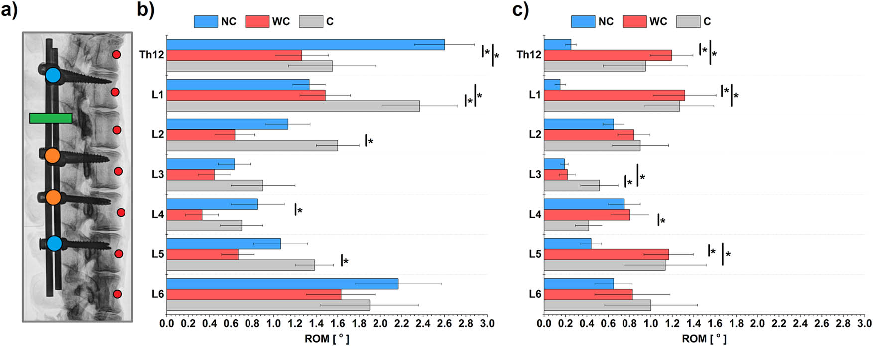
Figure 5
Graph of angular range of motion, in the sagittal plane, of the Th12–L6 vertebrae during axial spine compression for the groups C, NC, and WC: (a) scheme of the arrangement of markers (red points) and stabilizer elements – screws with a sliding nut (blue), standard non-sliding screws (orange), connector (green); (b) initial value of angular displacement after 100 cycles; and (c) final value of angular displacement after 100,000 cycles. *– Statistical significance (p < 0.05).
After 100,000 cycles, the mean mobility value for the entire spine section was lower than that after 100 cycles by 40% in C and WC and by over 60% in NC (Figure 5c). Following the high-cycle mechanical test, no visible differences between the mobility of vertebrae L3 and L4 with fixed screws and the remaining vertebrae were observed, although such differences were noticeable at the initial stage. Mobility of vertebrae Th12–L1 and L5–L6 in NC was statistically significantly lower than in C and WC. For these vertebrae, no visible differences in mobility were found between C and WC.
3.3. Digital image correlation
The analysis showed that mean total displacement values for the kinematic pair were lower in NC than in WC, both after 100 and after 100,000 cycles (Figure 6d). Analysis of main strains showed that after 100 cycles, mean strain values were higher in WC than in NC. However, after 100,000 cycles, this trend reversed, with higher mean strains in NC than in WC. An example distribution of engineering principal strain in the X direction for NC stabilization is shown in Figure 6b.
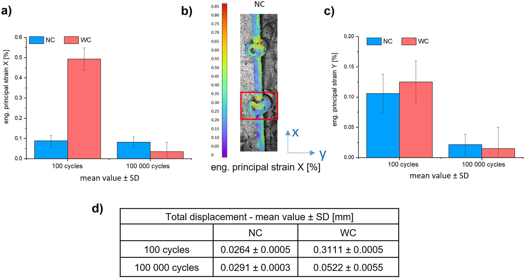
Figure 6
Mechanical parameters of sliding pedicle screw (L5 vertebra) in NC and WC. The value were obtained using the DIC method after 100 and 100,000 cycles: (a) engineering principal strain X (%); (b) exemplary distribution engineering principal strain X (%) of NC stabilization; (c) engineering principal strain Y (%); and (d) value of the total displacement in groups NC and WC.
4. Discussion
The present tests characterized the stability of the SOCORE GGS from NovaSpine used to correct scoliosis in children during growth. We also evaluated the effect of DLC coating on the biomechanical behaviour of this stabilizer system. Most studies published to date have analysed biomechanical properties of GGS over relatively small number of cycles [10], without considering that, in clinical settings, the implant is exposed to repeated long-term fatigue loads. For this reason, we analysed the selected stabilization system in the Th12–L6 section under prolonged axial loading for 100,000 cycles.
Ouyang et al. [10] demonstrated that, during flexion–extension and lateral bending with a moment of 2.5 Nm, both conventional fixed rod systems and a growing rod with sliding pedicle screw system (GRSPSS) are characterized by similar stability and stiffness.
Unlike the GRSPSS system, the SOCORE GGS is based on a combination of fixed pedicle screws and sliding pedicle screws. At the initial loading stage (100 cycles), differences in height loss (H) between the spine without a stabilizer (C) and with the conventional titanium alloy stabilizer (NC) were not significant and did not exceed 0.38 mm (Figure 4a). At the same time, the stabilizer significantly increased stiffness of the studied spinal section (k = 798 ± 30 N/mm for C and k = 946 ± 129 N/mm for NC; Figure 4b). In accordance with the implant settings, the lowest angular mobility was obtained at L3 and L4, where conventional fixed screws were used. Mobility of vertebrae L1 and L5, in which sliding screws were implanted, did not exceed 1.4° in NC and was lower than in the non-instrumented system (Figure 5b). In the present study, the use of the stabilizer was associated with increased mobility at the vertebral levels adjacent to the sliding screws, particularly at Th12 and L6.
The same study also showed that sliding connections between the screw and rod contribute to lower stiffness in axial rotation, indicating a higher degree of maintained mobility and less rotational control in the adjacent segments [10].
Our analysis of mechanical parameters after 100,000 cycles showed a statistically significantly higher value of height loss (H) and stiffness coefficient (k) in the system with the stabilizer (NC) than in the non-instrumented system (C), whereas no increase in mobility of individual vertebrae was observed (Figure 5c). Still, loading in the growth-guided system (NC) resulted in a statistically significant decrease in mobility in the upper segments (Th12–L1), whereas no significant relationship was demonstrated in the lower segments (L5–L6). On this basis, it can be stated that, despite greater mobility at the initial stage of cyclic loading and significantly higher stiffness after the mechanical test, the SOCORE GGS system did not show features suggesting development of complications or malfunctions under the present loading conditions.
Results obtained from DIC measurements indicate significant differences in the behaviour of kinematic pairs in NC and WC. At the initial stage of testing (after 100 cycles), WC had higher displacement and strain values, which may imply a more intense running-in process. After 100,000 cycles, this trend was reversed, suggesting better contact stabilization in WC and a possible change in the deformation mechanism in NC.
As the literature shows, at the initial stage of tribological tests, the observed values of displacement and strains of rubbing components are clearly higher, and this results from the intense effect of microgeometric surface unevenness and mismatch between surfaces [12,22]. These phenomena are characteristic for the breaking-in stage, during which local plastic deformation and wear occur. The breaking-in process results in adaptation of the contact surfaces and, when it is completed, these values are stabilized. After 100,000 cycles, the contact stabilizes, the surfaces become smoother, and the displacement and strains values significantly decrease, implying that the tribological system achieved the steady state [23]. Although the low coefficient of friction of the DLC coatings facilitates a reduction in the resistance forces on contact, during the breaking-in stage, the values of displacement and strains can be higher [24,25]. This results from surface mismatch, local stress concentrations, and dynamic microslides that occur before the tribological contact achieves the steady state. On the basis of the assessment of the displacement and strains distribution and conducted angle measurements, the authors demonstrated that in the case of the axial compression, the higher values of displacement and strains and the greater ranges of mobility for individual vertebra were obtained in the case of the stabilizing system with the DLC coating applied.
4.1. Potential clinical relevance
GGSs depend on controlled sliding at the rod–screw interface; excessive friction or altered interface kinematics may unintentionally increase construct constraint, shift motion to adjacent levels, and contribute to failure modes such as rod deformation or screw loosening. In the present highly cyclic axial loading model, DLC-coated sliding components exhibited a different interface kinematic response. They maintained segmental mobility closer to the non-instrumented condition at selected levels compared with the non-coated construct. If confirmed under multi-axis fatigue and dedicated wear/debris assessments, DLC coating could represent a practical strategy to tune long-term sliding behaviour and potentially improve implant durability while limiting adverse responses related to wear products.
4.2. Limitations
The main limitation of the study is the use of the pig spine model for biomechanical tests with the GGS. This results from problems with obtaining specimens from human cadavers below 10 years of age with signs of early-onset scoliosis. The pig spine is used in biomechanical studies due to geometrical dimensions of the vertebrae, mechanical properties of individual structures, and the physiological curvature and range of mobility of the lumbar spine, which are similar to those of the human spine [26–28].
The lumbar spine of the pig is highly similar to the human one in terms of the vertebra structure and geometry [27,29]. Busscher et al. [27] confirmed that biomechanics of the lower spine of the pig is similar to that of the human spine. The mean length of the spine differs by just 0.1 mm. However, there are differences in curvatures – in humans, cervical and lumbar lordoses are shallower, and the thoracic kyphosis is greater than in pigs. The vertebral heights are comparable, and similarities in the spinal canal structure indicate the usefulness of the pig model in studies on transpedicular stabilization [27,30,31].
In our study, the spines did not show deformity resulting from scoliosis, which could influence stability, load transfer in the growth-guided system, and the degree of material wear in mobile components. At the same time, animal models, including the pig spine, are commonly used in studies in which spinal sections are subjected to cyclic compression loads [10,32,33].
5. Conclusion
Under highly cyclic axial compression, DLC coating of GGS components did not increase the overall construct stiffness compared with the non-coated system. After 100,000 cycles, the coated construct showed slightly lower stiffness and a different local kinematic response at the rod–screw interface. Segmental mobility at Th12–L1 and L5–L6 remained closer to the non-instrumented condition in the coated group, whereas reduced motion was observed in the non-coated construct. These findings suggest that DLC coating may modify the mechanical behaviour of GGSs without increasing construct rigidity. Further studies should determine whether these effects are maintained under multi-axis loading and whether they are associated with favourable long-term tribological performance.
Acknowledgements
Special thanks to Ewelina Brunicka and Grzegorz Dworszczak from NovaSpine Sp. z o. o, Wrocław, Poland for supporting the research and cooperation in the project.
Funding information
Work to be implemented under the Intelligent Development Operational Program 2014–2020 - Project no. POIR.04.01.01-00-0020/19-00 as part of the Joint Venture with the Lower Silesian Voivodeship “Lower Silesian Biomedical Technology Zone.” Project title: Modification of the internal stabilization system modelling the spine during growth. The funder had no role in study design; data collection, analysis, or interpretation; manuscript preparation; or the decision to submit for publication.
Author contributions
Małgorzata Żak: Conceptualization, Data curation, Formal analysis, Investigation, Methodology, Visualization, Writing – original draft, Writing – review & editing. Sylwia Szotek: Conceptualization, Data curation, Investigation, Methodology, Visualization, Writing – original draft, Writing – review & editing. Klaudia Szkoda-Poliszuk: Conceptualization, Data curation, Investigation, Methodology, Visualization, Writing – original draft, Writing – review & editing. Krzysztof Kołtowski: Investigation. Piotr Menartowicz: Investigation. Celina Pezowicz: Conceptualization, Funding acquisition, Investigation, Methodology, Project administration, Writing – original draft, Writing – review & editing.
Conflict of interest statement
The authors declare that they have no known competing financial interests or personal relationships that could have appeared to influence the work reported in this manuscript.
Data availability statement
The data supporting the findings of this study are available from the corresponding author upon reasonable request.