
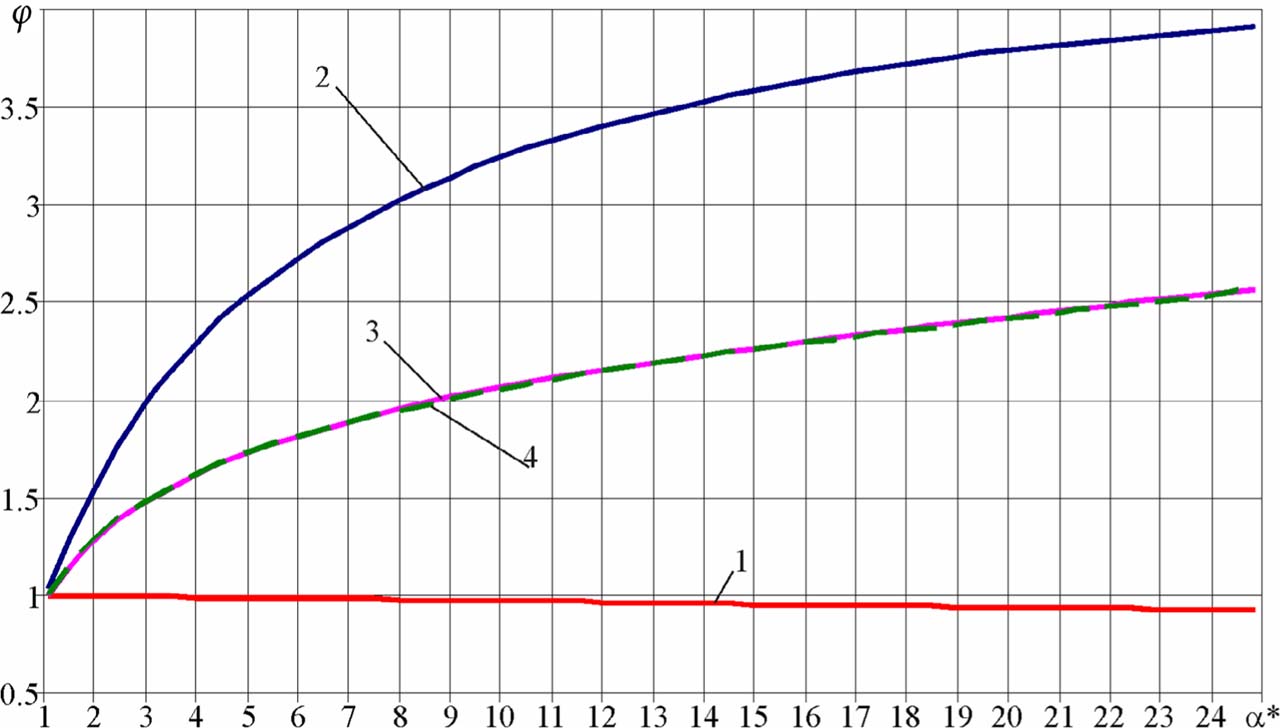
Fig.1.
Ejector nozzle thrust augmentation ratio vs. α*: 1 – first solution, ideal; 2 – second solution, ideal; 3 – second solution, with nozzle underexpansion losses from 1D theory; 4 – second solution, with nozzle underexpansion losses from 2D theory.
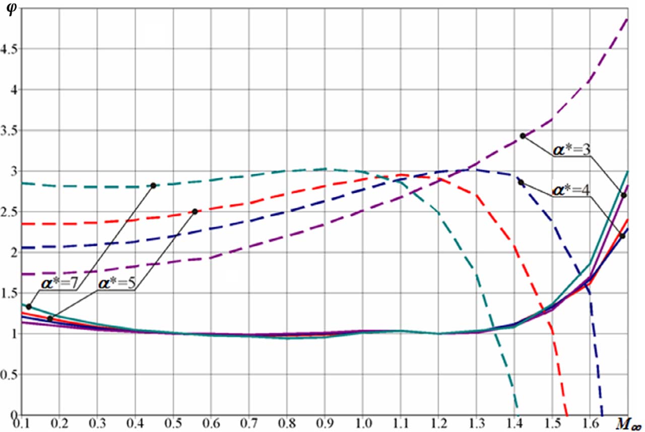
Fig. 2.
Ejector nozzle thrust augmentation ratio vs. flight Mach number (without taking into account losses).

Fig. 3.
Computational domain (configurations 1–5).
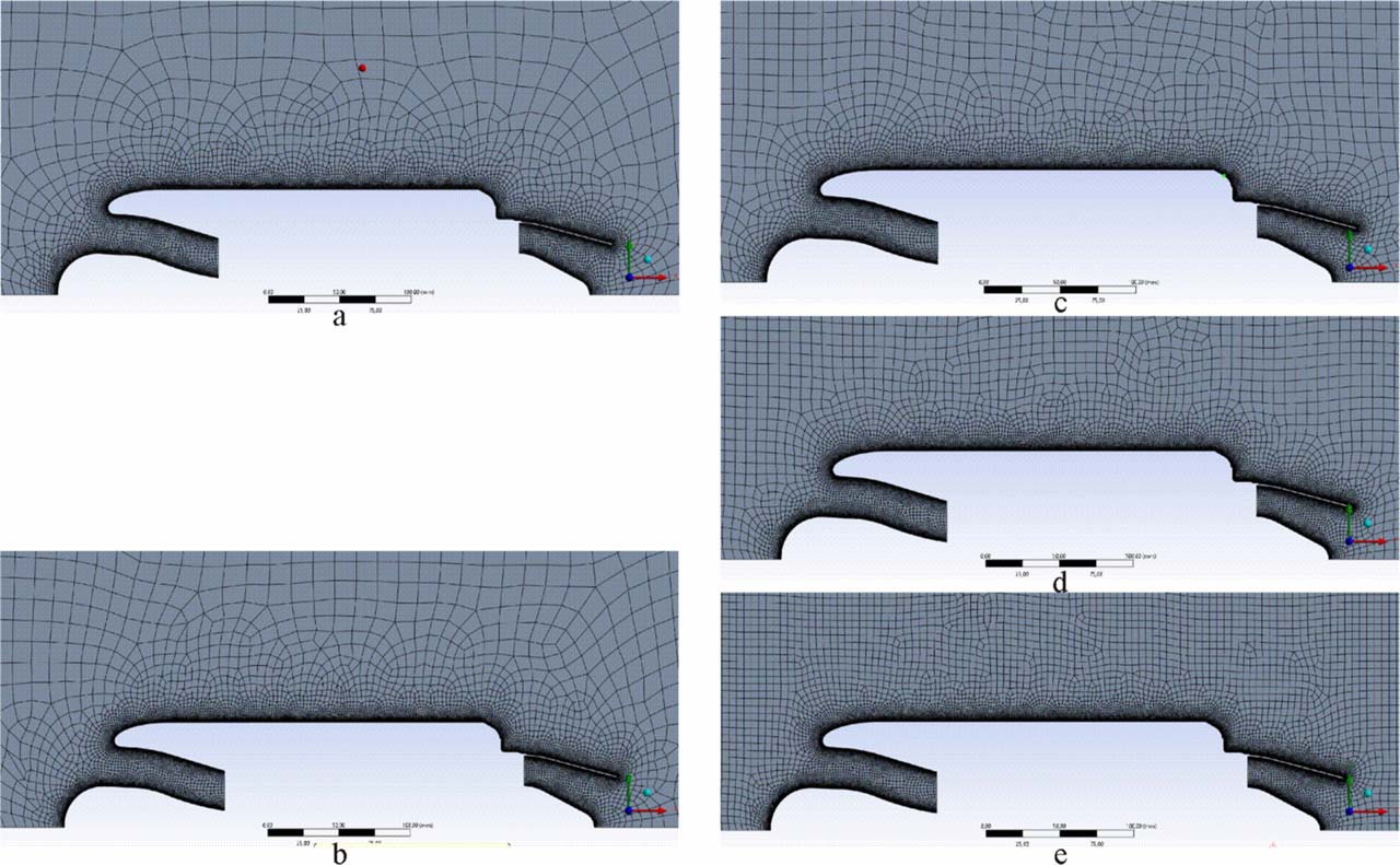
Fig. 4.
The five meshes considered: a – 20 mm; b – 15 mm; c – 10 mm; d – 7.5 mm; e – 5 mm.
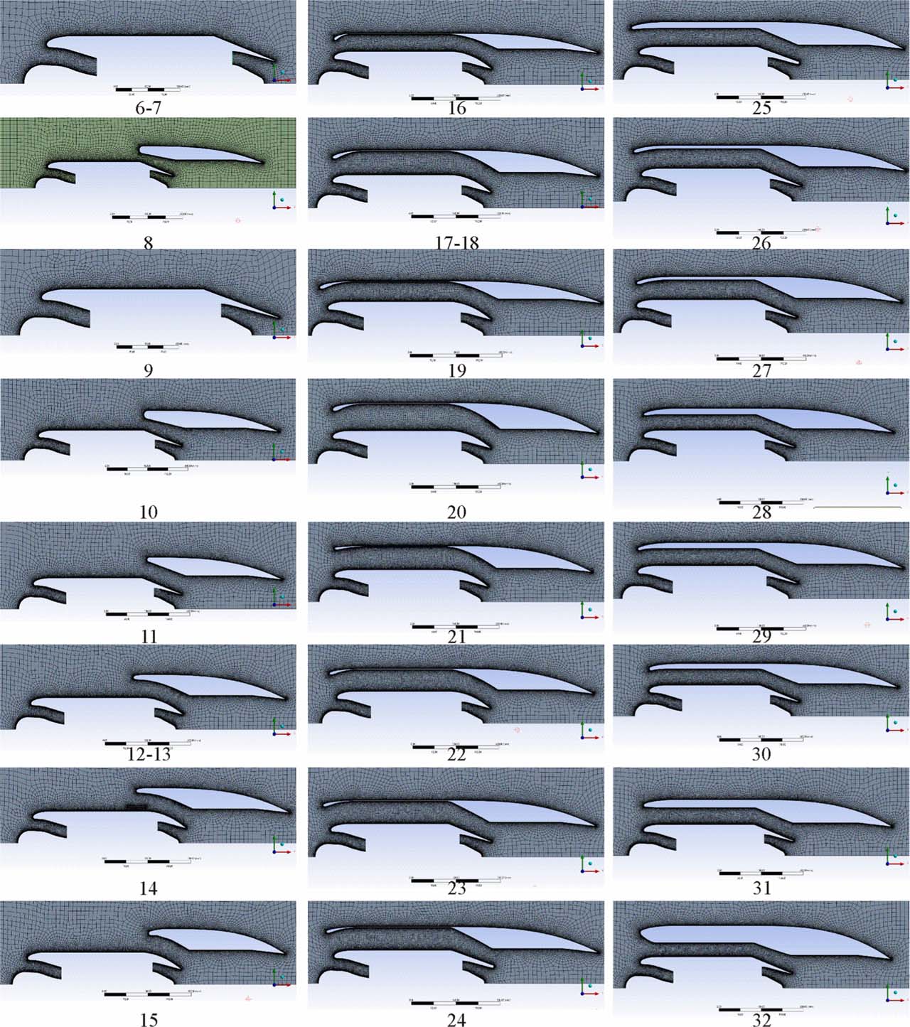
Fig. 5.
Configurations considered (α*= 5).
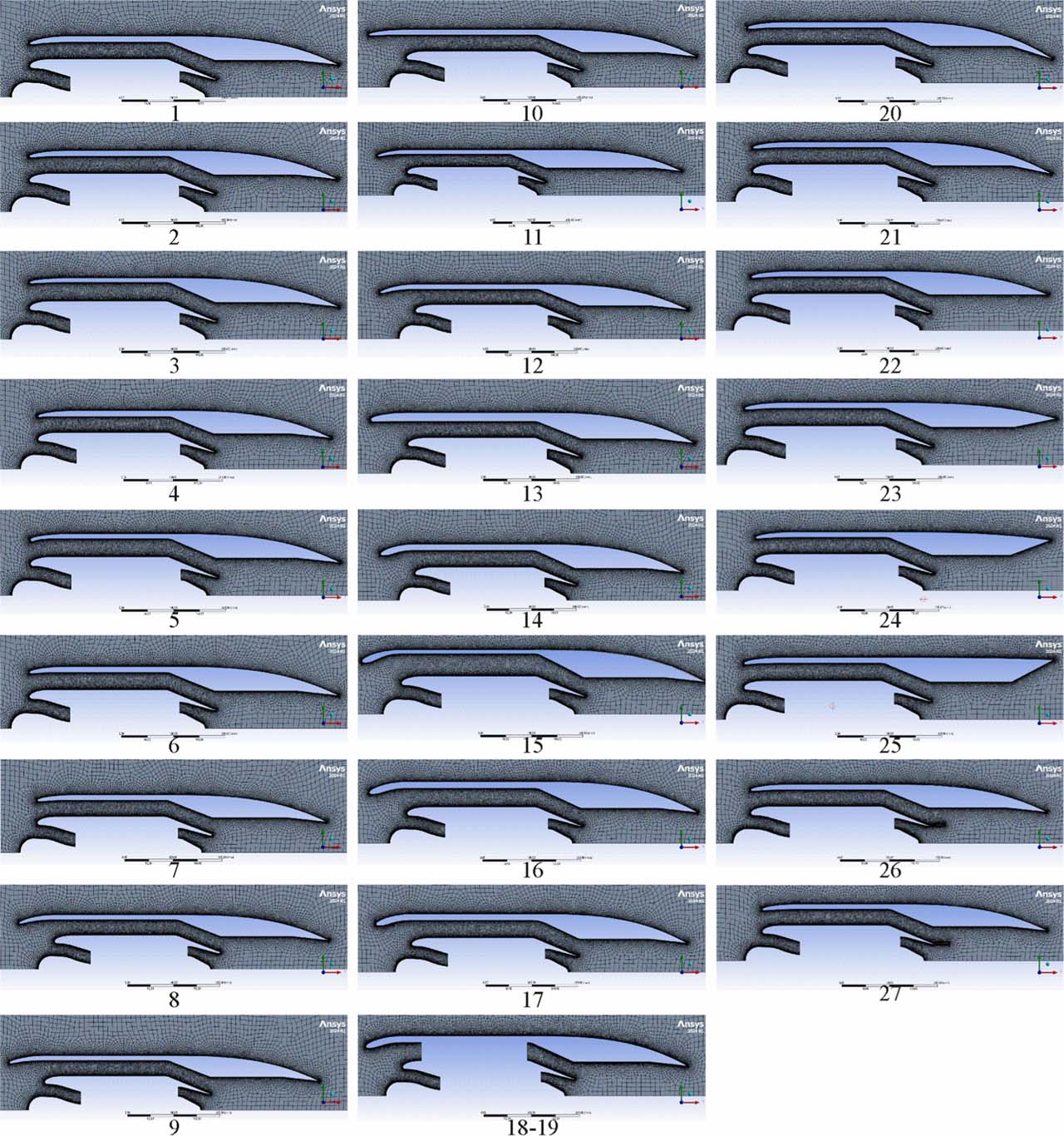
Fig. 6.
Configurations considered (α*= 4).
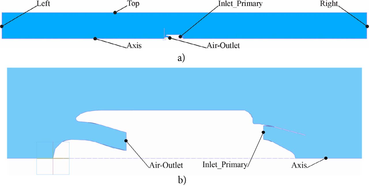
Fig. 7.
Model boundaries.
Table 1.
Values of corresponding boundary parameters.
| Boundary/Parameter | Total/static pressure, Pa | Turbulence intensity, % | Mach number | Flow rate, kg/s | Total/static temperature, K |
|---|---|---|---|---|---|
| Left (Pressure-far-field) | –/101325 | 1.0 | 0.6 | – | –/288.15 |
| Top (Pressure-far-field) | –/101325 | 1.0 | 0.6 | – | –/288.15 |
| Right (Pressure outlet) | –/101325 | 1.0 | – | – | 308.89/– |
| AirOutlet (Mass-flow-outlet) | – | – | – | 0.99 | – |
| InletPrimary (Pressure-inlet) | 209787/– | 10.0 | – | – | 993.05/– |
Table 2.
Parameter values on the corresponding meshes.
| Mesh, | Integral parameter, N | Representative mesh cell size, m |
|---|---|---|
| 1 (20 × 0.40 mm) | 395.65 | 1.24×10⁻² |
| 2 (15 × 0.30 mm) | 396.21 | 1.01×10⁻² |
| 3 (10 × 0.20 mm) | 396.31 | 7.46×10⁻³ |
| 4 (7.5 × 0.15 mm) | 394.66 | 5.94×10⁻³ |
| 5 (5 × 0.10 mm) | 395.60 | 4.23×10⁻³ |
Table 3.
Comparative estimation of the computational results.
| Parameter | Meshes 1–2–3 | Meshes 2–3–4 | Meshes 3–4–5 |
|---|---|---|---|
| h1, m | 7.46×10⁻³ | 5.94×10⁻³ | 4.23×10⁻³ |
| h2, m | 1.01×10⁻² | 7.46×10⁻³ | 5.94×10⁻³ |
| h3, m | 1.24×10⁻² | 1.01×10⁻² | 7.46×10⁻³ |
| P1, N | 396.31 | 394.66 | 395.60 |
| P2, N | 396.21 | 396.31 | 394.66 |
| P3, N | 395.65 | 396.21 | 396.31 |
| r32 | 1.229 | 1.350 | 1.255 |
| r21 | 1.350 | 1.255 | 1.403 |
| s | 1 | −1 | −1 |
| p | 8.525 | 17.788 | 2.119 |
| CR | 0.192 | −15.573 | −0.568 |
| [0; 1) – monotonic convergence | (−∞; −1) – oscillating divergence | [−1; 0) – oscillating convergence | |
| fex, N | 396.32 | 394.63 | 396.49 |
| e32, % | 0.140 | 0.027 | 0.419 |
| e21, % | 0.027 | 0.419 | 0.238 |
| GCI32, % | 0.036 | 0.000 | 0.848 |
| GCI21, % | 0.003 | 0.009 | 0.283 |
| < 1% – for detailed calculations | < 1% – for detailed calculations | < 1% – for detailed calculations | |
| AR | 1.000 | 0.0003 | 1.463 |
| [0.95; 1.05] – optimum | (−∞; 0.95) – mesh should be improved | (1.05; ∞) – mesh should be improved | |
| hreq | 3.74×10⁻³ | 4.57×10⁻³ | 2.33×10⁻⁶ |
Table 4.
Differences of integral parameter calculations.
| Parameter | Mesh 20 mm | Mesh 15 mm | Mesh 10 mm | Mesh 7.5 mm | Mesh 5 mm |
|---|---|---|---|---|---|
| Δm, % | −4.438 | −4.173 | −4.076 | −4.605 | −4.329 |
| Δv, % | −17.564 | −16.510 | −16.232 | −17.036 | −16.542 |
| Δp, % | 25.717 | 24.289 | 23.876 | 24.894 | 24.288 |
| ΔNozzle Th, % | −2.668 | −2.488 | −2.442 | −2.888 | −2.640 |
| ΔTh, % | −3.494 | −3.259 | −3.333 | −3.737 | −3.507 |
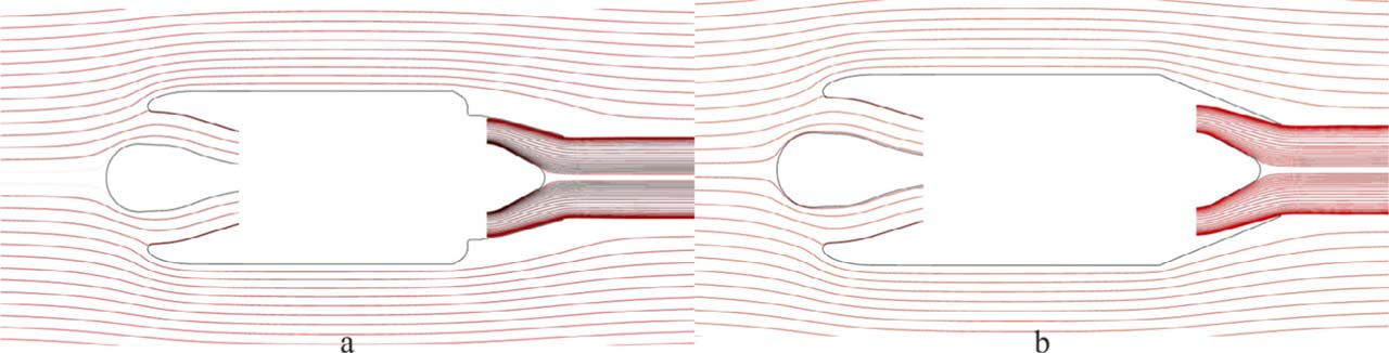
Fig. 8.
Pathline patterns for configurations 3 and 6 (α* = 5).
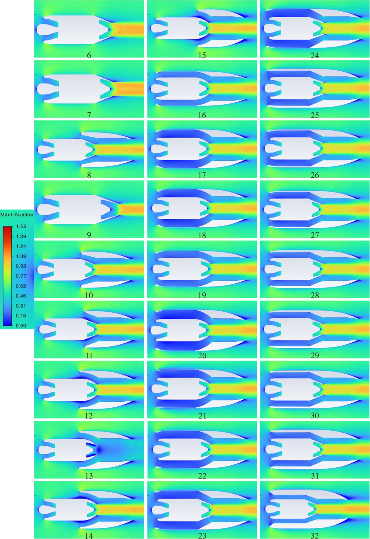
Fig. 9.
Fields of Mach number for the configurations considered (α* = 5).
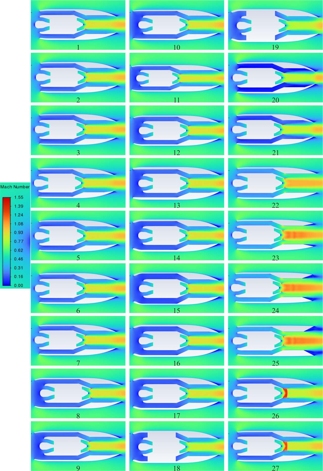
Fig. 10.
Fields of Mach number for the configurations considered (α* = 4).
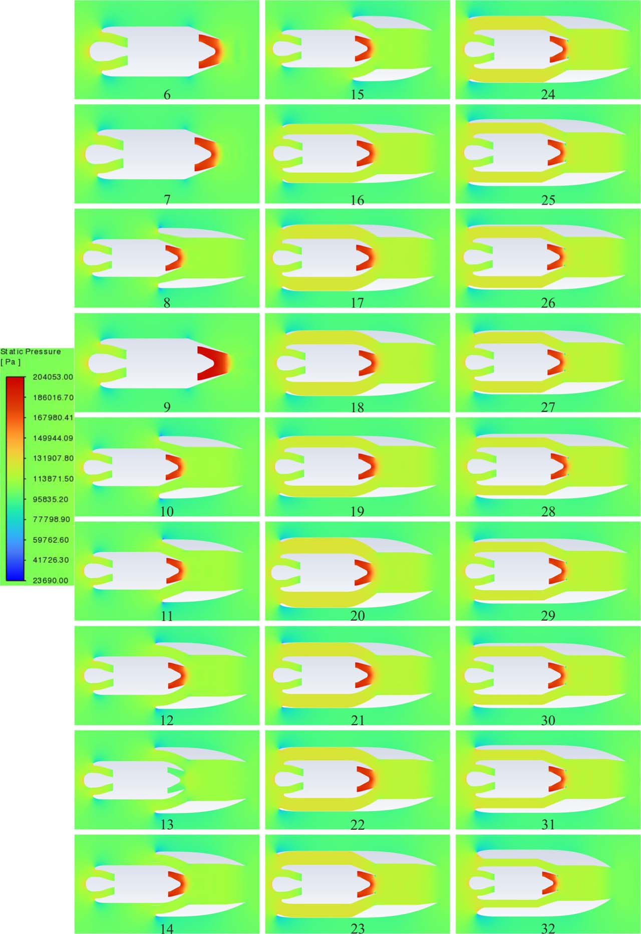
Fig. 11.
Fields of static pressure for the configurations considered (α* = 5).
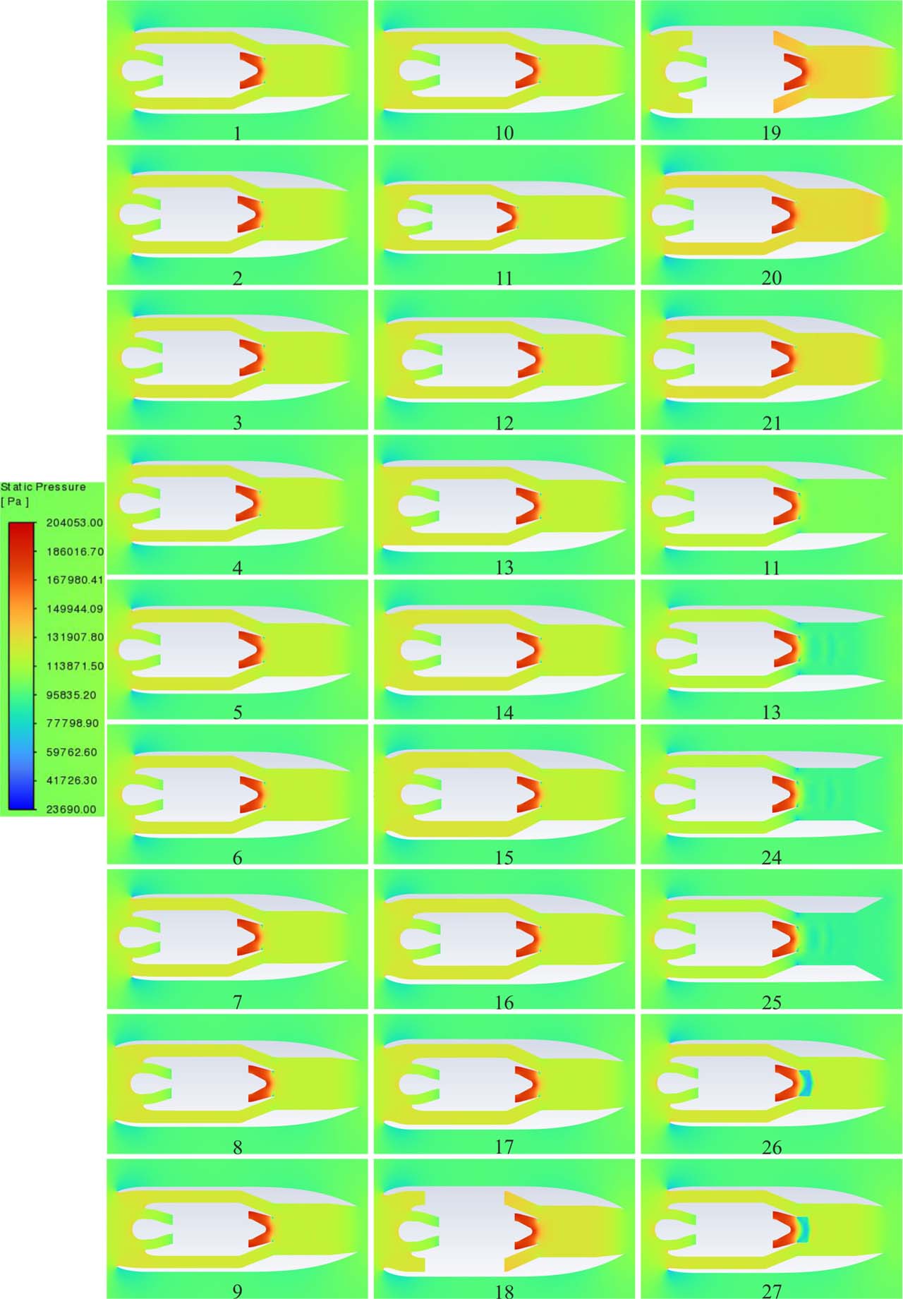
Fig. 12.
Fields of static pressure for the configurations considered (α* = 4).
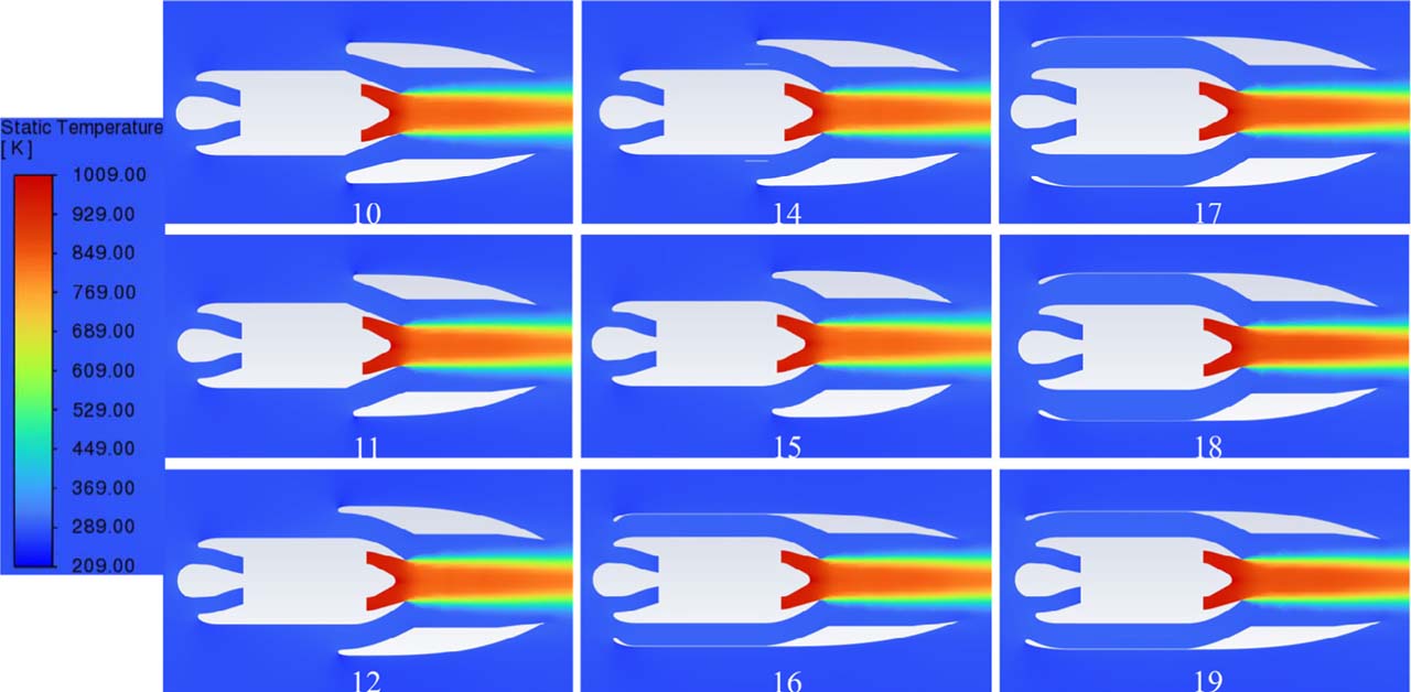
Fig. 13.
Fields of static temperature for some of the configurations considered (α* = 5).
Table 5.
Results of integral parameter calculations.
| Parameter/Configuration | Secondary flow Mach number at the entrance of mixing chamber | Primary flow rate, kg/s | Entrainment ratio | Thrust, N | Augmentation ratio, φ |
|---|---|---|---|---|---|
| Alperin | 0.4119 | — | 2.868 | — | 1.72 |
| Base engine | — | 1.0102 | — | 409.978 | — |
| 1 (α* = 5) | — | 0.96537 | — | 395.65 | — |
| 2 (α* = 5) | — | 0.96804 | — | 396.21 | — |
| 3 (α* = 5) | — | 0.96903 | — | 396.31 | — |
| 4 (α* = 5) | — | 0.96368 | — | 394.66 | — |
| 5 (α* = 5) | — | 0.96647 | — | 395.60 | — |
| 6 (α* = 5) | — | 0.97104 | — | 394.35 | — |
| 7 (α* = 5) | — | 0.97484 | — | 395.92 | — |
| 8 (α* = 5) | 0.32082 | 0.96839 | 2.31028 | 299.26 | 0.72994 |
| 9 (α* = 5) | — | 0.61498 | — | 251.28 | — |
| 10 (α* = 5) | 0.32750 | 0.97310 | 2.33550 | 301.40 | 0.73516 |
| 11 (α* = 5) | 0.34470 | 0.96667 | 2.42548 | 305.87 | 0.74607 |
| 12 (α* = 5) | 0.33997 | 0.96408 | 2.41586 | 305.31 | 0.74470 |
| 13 (α* = 5) | 0.46743 | 0.23817 | 13.57310 | 227.01 | 0.55370 |
| 14 (α* = 5) | 0.34294 | 0.96564 | 2.40173 | 304.53 | 0.74279 |
| 15 (α* = 5) | 0.35425 | 0.96738 | 2.42944 | 298.82 | 0.72887 |
| 16 (α* = 5) | 0.34583 | 0.94622 | 2.83003 | 365.90 | 0.89247 |
| 17 (α* = 5) | 0.34722 | 0.94040 | 2.97538 | 382.91 | 0.93398 |
| 18 (α* = 5) | 0.34472 | 0.93197 | 2.98313 | 383.83 | 0.93622 |
| 19 (α* = 5) | 0.35423 | 0.93440 | 2.95817 | 385.23 | 0.93964 |
| 20 (α* = 5) | 0.31634 | 0.92613 | 2.84300 | 381.47 | 0.93047 |
| 21 (α* = 5) | 0.33955 | 0.93160 | 2.83899 | 386.71 | 0.94323 |
| 22 (α* = 5) | 0.34451 | 0.92628 | 2.85432 | 386.43 | 0.94256 |
| 23 (α* = 5) | 0.37377 | 0.97795 | 2.66855 | 407.85 | 0.99482 |
| 24 (α* = 5) | 0.40219 | 0.98181 | 2.62750 | 405.87 | 0.98997 |
| 25 (α* = 5) | 0.39948 | 0.98102 | 2.61869 | 401.61 | 0.97958 |
| 26 (α* = 5) | 0.37102 | 0.97963 | 2.64032 | 410.45 | 1.00115 |
| 27 (α* = 5) | 0.37075 | 0.98006 | 2.62426 | 404.57 | 0.98681 |
| 28 (α* = 5) | 0.36716 | 0.98029 | 2.60928 | 402.62 | 0.98206 |
| 29 (α* = 5) | 0.37423 | 0.97742 | 2.60485 | 406.13 | 0.99062 |
| 30 (α* = 5) | 0.36818 | 0.97993 | 2.61096 | 402.31 | 0.98130 |
| 31 (α* = 5) | 0.36976 | 0.98077 | 2.61755 | 403.16 | 0.98337 |
| 32 (α* = 5) | 0.36390 | 0.97955 | 2.54888 | 378.82 | 0.92399 |
| Alperin | 0.379 | — | 2.008 | — | 1.62 |
| Base engine | — | 1.0102 | — | 409.978 | — |
| 1 (α* = 4) | 0.35692 | 0.97862 | 2.04513 | 402.43 | 0.98158 |
| 2 (α* = 4) | 0.35962 | 0.97930 | 2.05995 | 398.65 | 0.97238 |
| 3 (α* = 4) | 0.35893 | 0.97805 | 2.06253 | 399.83 | 0.97525 |
| 4 (α* = 4) | 0.35652 | 0.97793 | 2.04692 | 404.07 | 0.98559 |
| 5 (α* = 4) | 0.35750 | 0.97854 | 2.04527 | 397.83 | 0.97036 |
| 6 (α* = 4) | 0.35814 | 0.97848 | 2.05250 | 399.17 | 0.97363 |
| 7 (α* = 4) | 0.36632 | 0.97972 | 2.03578 | 405.58 | 0.98928 |
| 8 (α* = 4) | 0.36516 | 0.97918 | 2.04474 | 406.69 | 0.99198 |
| 9 (α* = 4) | 0.35050 | 0.97629 | 2.06375 | 400.55 | 0.97699 |
| 10 (α* = 4) | 0.35007 | 0.97877 | 2.05843 | 400.61 | 0.97715 |
| 11 (α* = 4) | 0.34451 | 0.97490 | 2.03757 | 402.30 | 0.98127 |
| 12 (α* = 4) | 0.35006 | 0.97648 | 2.06037 | 403.69 | 0.98467 |
| 13 (α* = 4) | 0.35034 | 0.98014 | 2.04143 | 402.45 | 0.98165 |
| 14 (α* = 4) | 0.35651 | 0.97861 | 2.04413 | 398.08 | 0.97097 |
| 15 (α* = 4) | 0.35597 | 0.98016 | 2.03369 | 395.00 | 0.96346 |
| 16 (α* = 4) | 0.35525 | 0.97989 | 2.04758 | 396.51 | 0.96716 |
| 17 (α* = 4) | 0.33691 | 0.97977 | 2.04349 | 395.18 | 0.96389 |
| 18 (α* = 4) | 0.38328 | 0.96484 | 2.33288 | 464.50 | 1.13298 |
| 19 (α* = 4) | 0.40915 | 0.94874 | 2.63502 | 512.45 | 1.24994 |
| 20 (α* = 4) | 0.09572 | 0.96209 | 0.61172 | 375.47 | 0.91584 |
| 21 (α* = 4) | 0.22171 | 0.96876 | 1.35933 | 400.38 | 0.97658 |
| 22 (α* = 4) | 0.58058 | 0.98028 | 2.89229 | 385.55 | 0.94040 |
| 23 (α* = 4) | 0.71614 | 0.98227 | 3.14938 | 315.27 | 0.76900 |
| 24 (α* = 4) | 0.70802 | 0.97691 | 3.19422 | 167.34 | 0.40818 |
| 25 (α* = 4) | 0.73642 | 0.98236 | 3.17467 | 13.62 | 0.03323 |
| 26 (α* = 4) | 0.35233 | 0.99994 | 1.94880 | 390.92 | 0.95351 |
| 27 (α* = 4) | 0.34880 | 0.99459 | 1.98429 | 399.94 | 0.97553 |
| 28 (α* = 4) | 0.37624 | 0.98298 | 2.32974 | 521.44 | 1.00290 |
| 29 (α* = 4) | 0.39163 | 0.97016 | 2.59136 | 612.90 | 0.98818 |
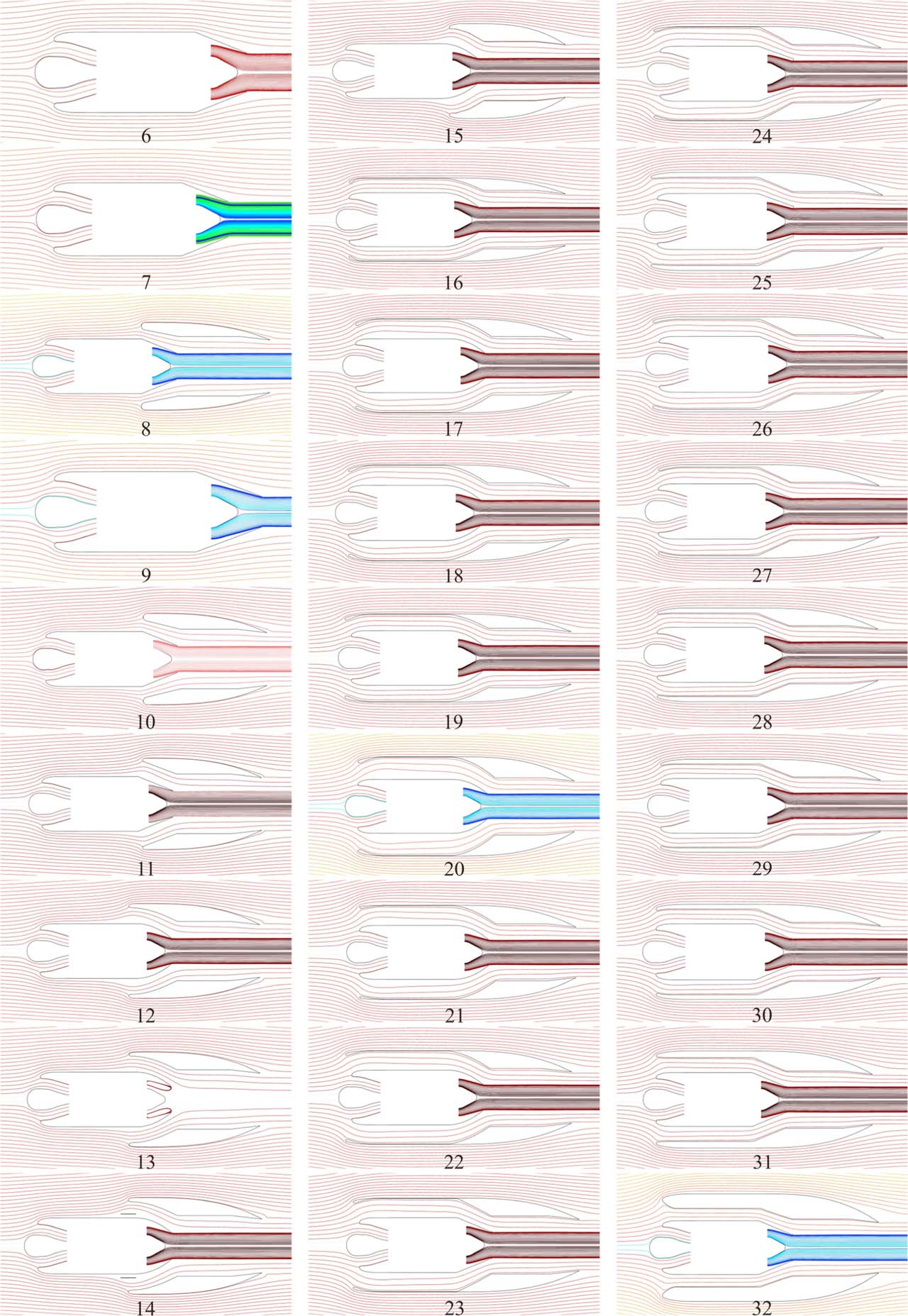
Fig. 14.
Pathline patterns for the configurations considered (α* = 5).
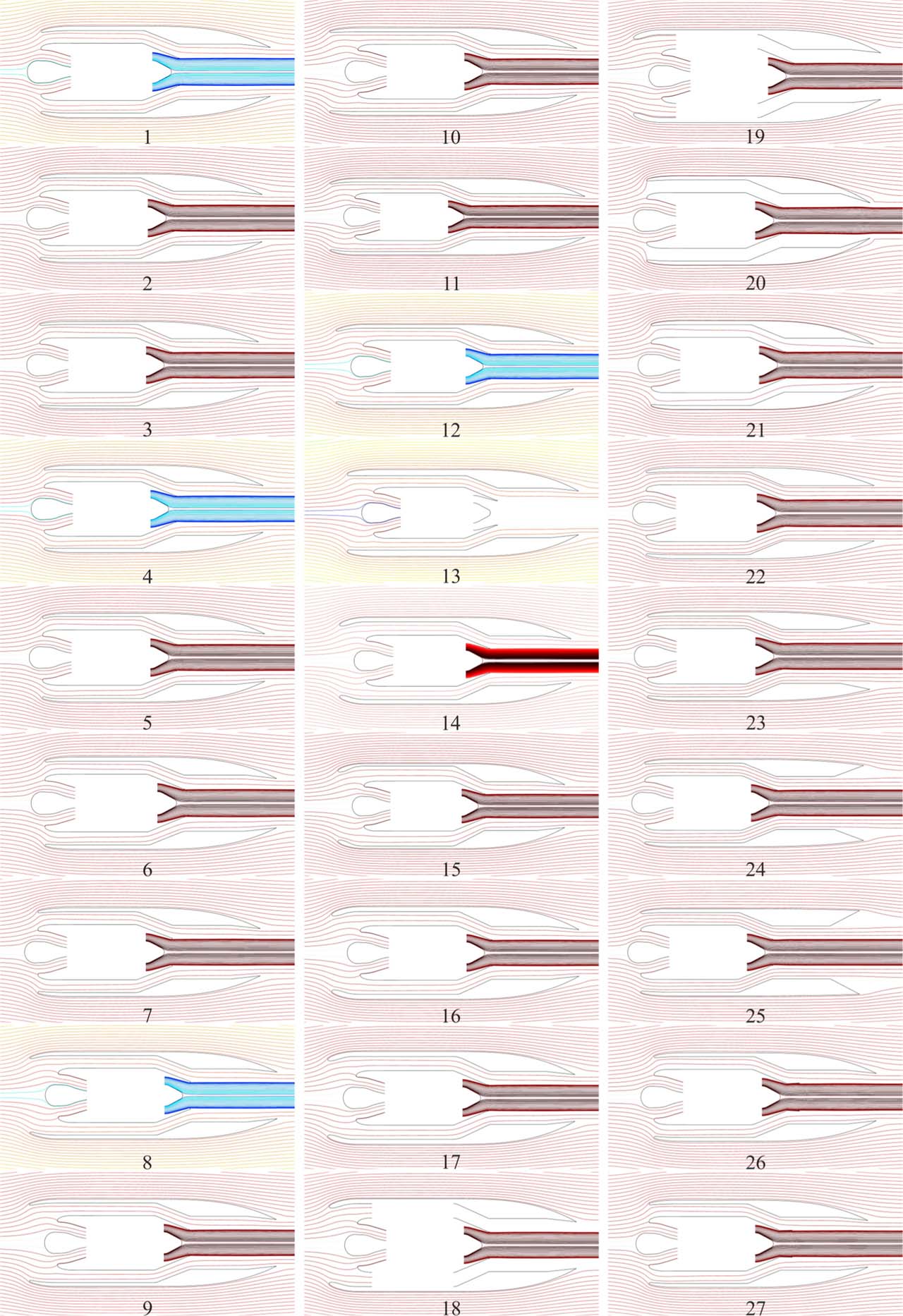
Fig. 15.
Pathline patterns for the configurations considered (α* = 4).
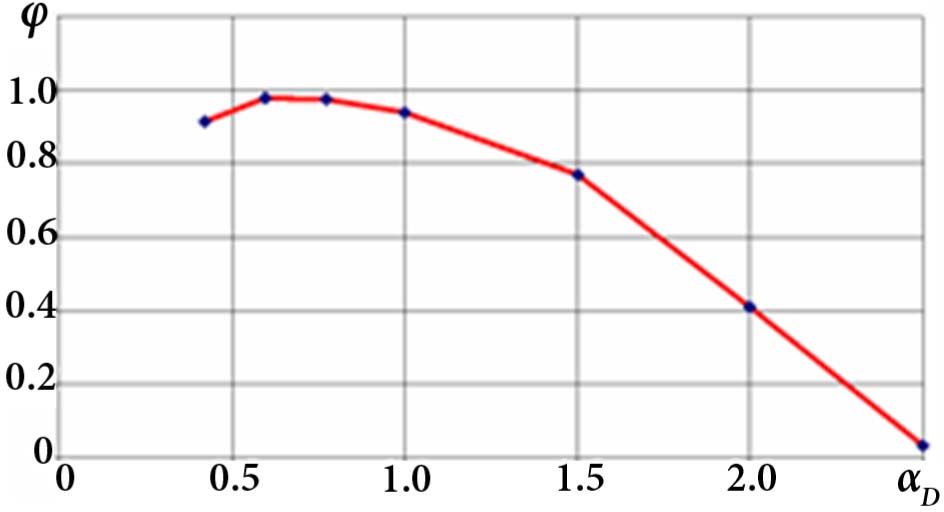
Fig. 16.
Thrust augmentation ratio (φ) vs. the ratio of the common exhaust unit exit area to the mixing chamber area (αD) (configurations 20, 21, 2, 22, 23, 24, 25) (α* = 4).
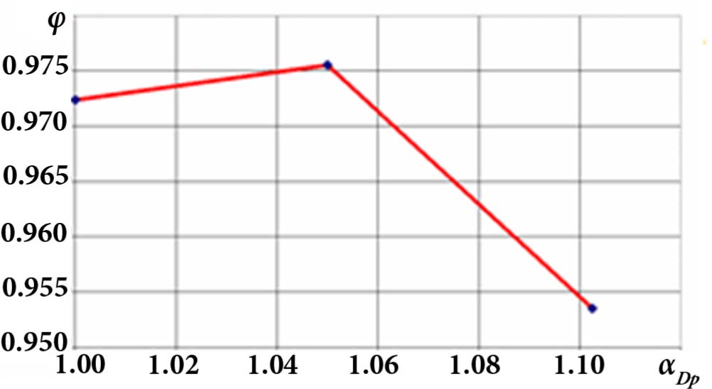
Fig. 17.
Thrust augmentation ratio (φ) vs. the ratio of the primary convergent-divergent nozzle exit area to its throat area (αDp) (configurations 2, 27, 26) (α* = 4).
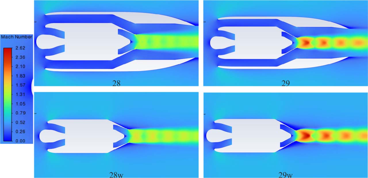
Fig. 18.
Fields of Mach number for configurations 28, 28w, 29 and 29w (α* = 4).
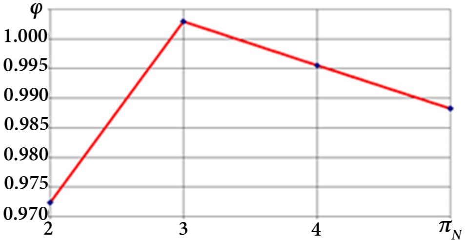
Fig. 19.
Thrust augmentation ratio (φ) vs. primary nozzle pressure ratio πN (the value at the point πN = 4 was interpolated).