
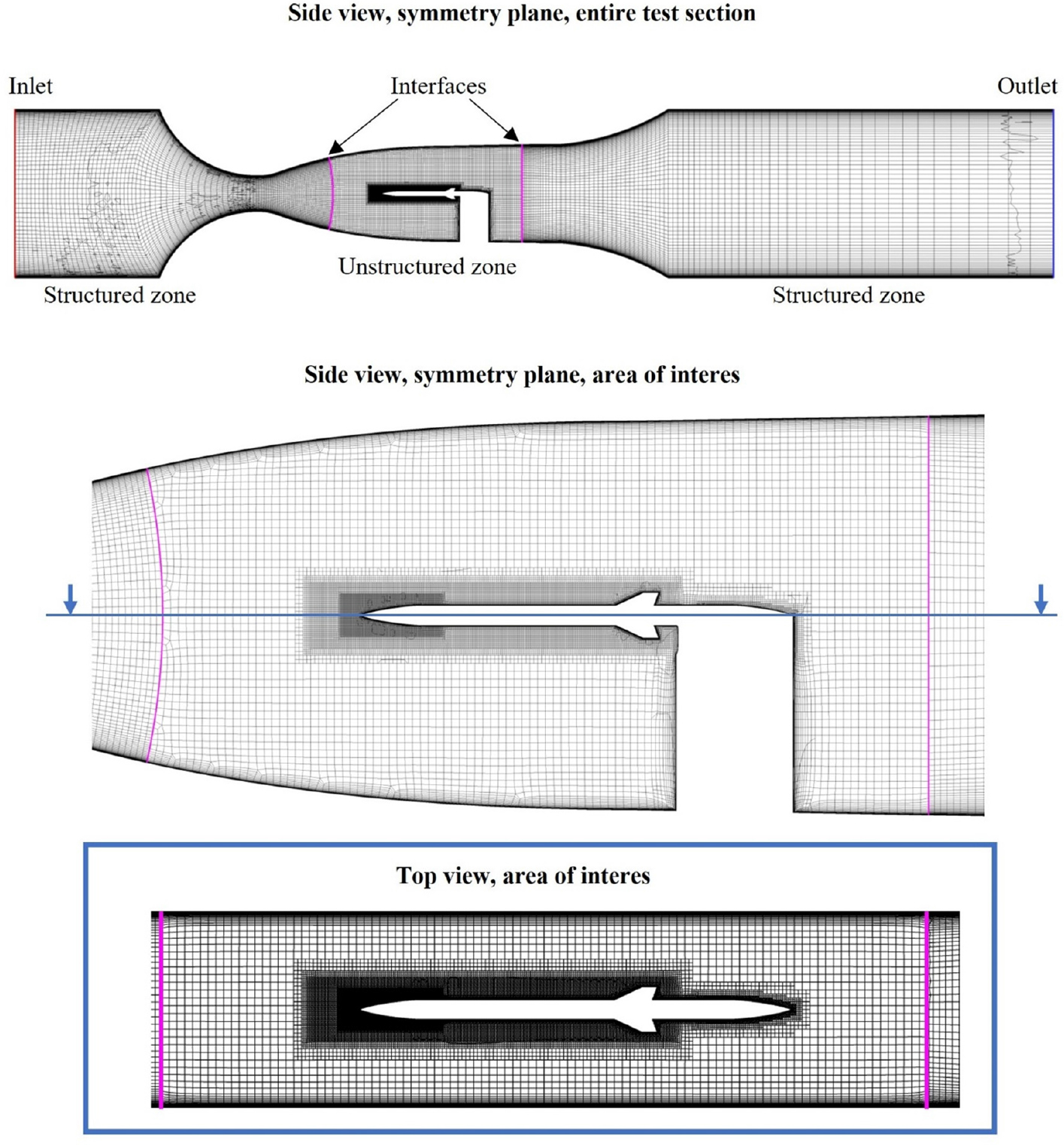
Fig. 1.
Grid used for numerical simulations. The boundary conditions are presented.
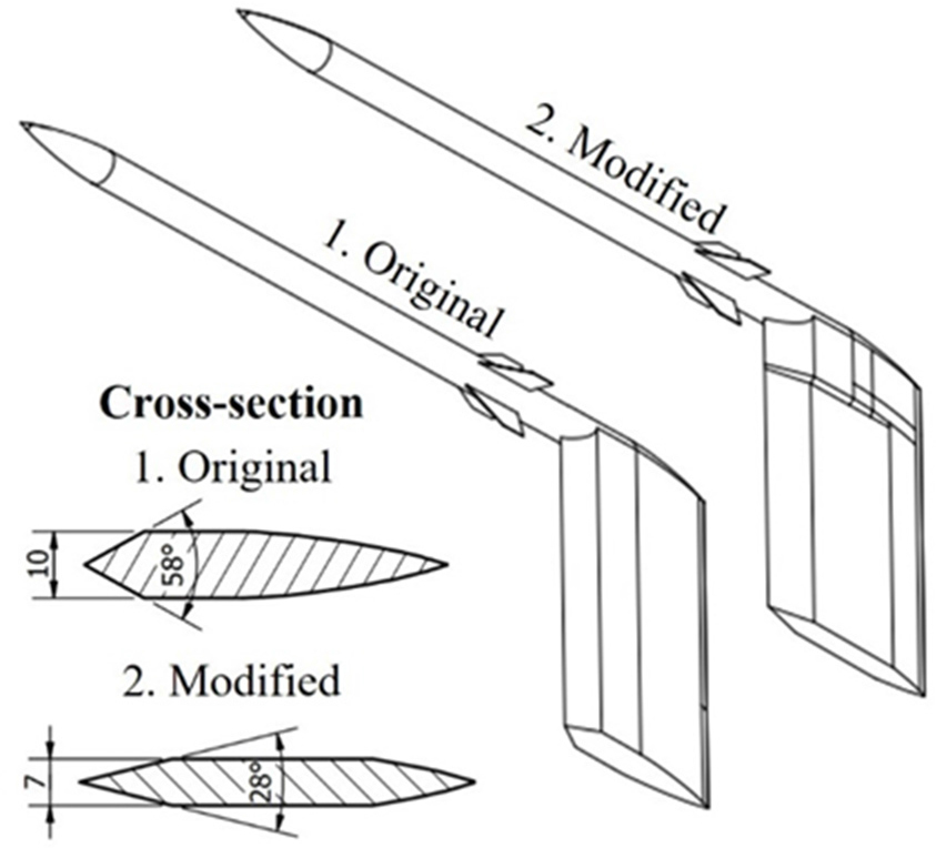
Fig. 2.
The sketch of the original and modified support, including the cross-section.
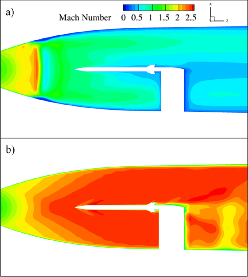
Fig. 3.
Mach contour plot for configurations with original support (a) and thin support (b) – side view.
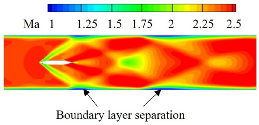
Fig. 4.
Mach number contour downstream of the support. Cross-section at half of the support span.
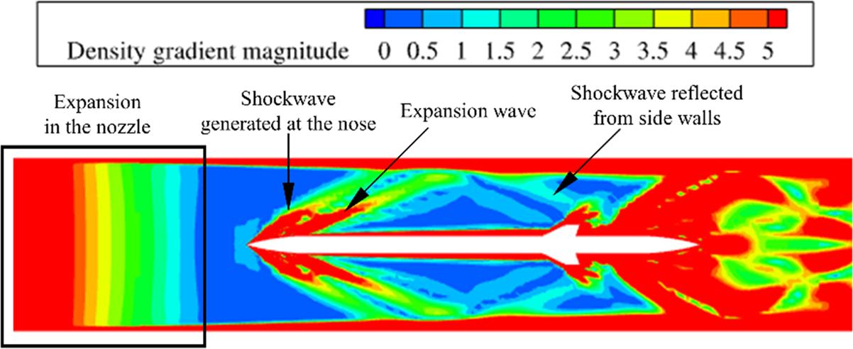
Fig. 5.
Density gradient magnitude for the model with original length – top view.
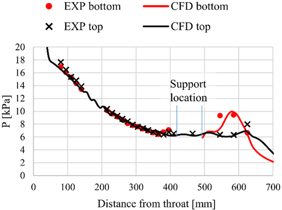
Fig. 6.
Pressure at top and bottom walls, measurements (EXP) and simulations (CFD).
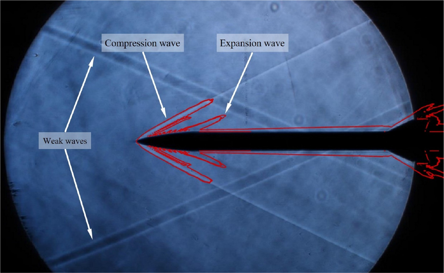
Fig. 7.
Schlieren visualization for configuration “Nose 2”. Red lines are the iso-surface of the density gradient magnitude of 5 kg/m4.
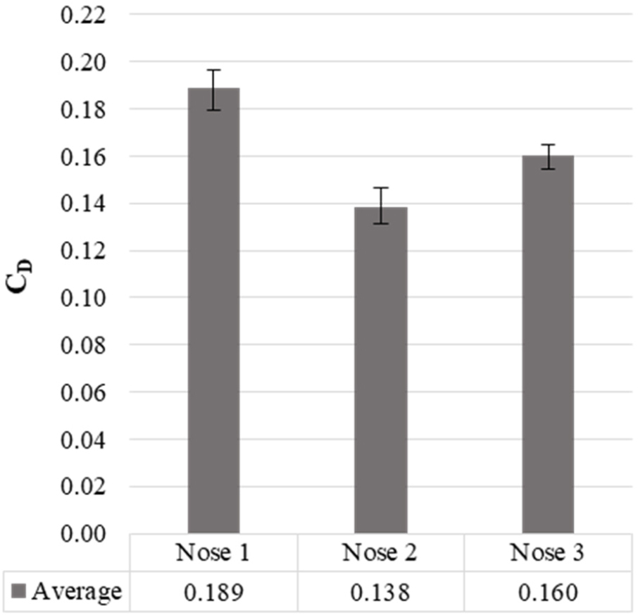
Fig. 8.
Drag coefficient for three nose configurations.