

Figure 1
Solution coding into a sequence of real numbers.
Source: Author’s contribution.

Figure 2
Uniform crossover.
Source: Author’s contribution.
Table 1
Interpretation of Pearson correlation coefficient based on [36].
| Correlation coefficient () | Strength of correlation |
|---|---|
| 0.00–0.19 | Very weak |
| 0.20–0.39 | Weak |
| 0.40–0.59 | Moderate |
| 0.60–0.79 | Strong |
| 0.80–1.00 | Very strong |
Source: Author’s contribution.
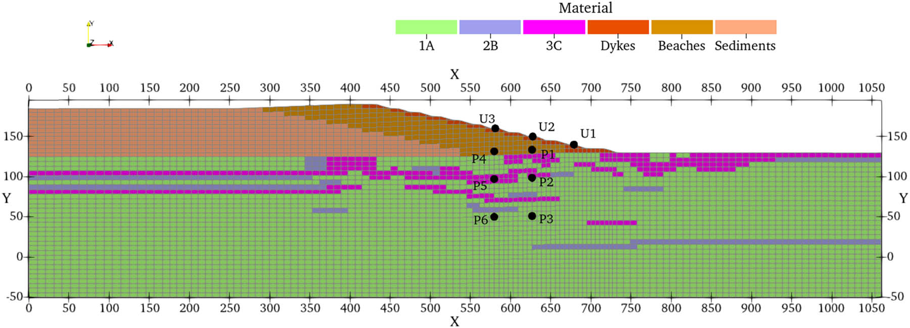
Figure 3
Numerical model and location of nodes selected as monitoring gauges.
Source: Author’s contribution.
Table 2
Material parameters used to generate synthetic monitoring data.
| Material | Case | E (MPa) | ν (−) | k x (m/s) | k y (m/s) | P c0 (kPa) | λ (−) | R (−) | c (kPa) | φ (°) | ME (−) | γ (kN/m3) | n (−) | S r (−) | α (1/m) | OCR (−) |
|---|---|---|---|---|---|---|---|---|---|---|---|---|---|---|---|---|
| 1A | 1.38 | 56.4 | 0.36 | 6.31 × 10⁻¹⁰ | 3.71 × 10⁻⁹ | 654.78 | 0.07 | 1.46 | 12.39 | 16.46 | 6.7 | 17.3 | 0.32 | 0 | 0.1 | 1.4 |
| 1.48 | 55.1 | 0.27 | 1.82 × 10⁻⁹ | 1.44 × 10⁻⁹ | 476.47 | 0.06 | 1.28 | 11.05 | 17.91 | 11.8 | ||||||
| 1.64 | 57.76 | 0.34 | 8.51 × 10⁻⁹ | 6.92 × 10⁻⁹ | 459.17 | 0.10 | 1.71 | 13 | 19.57 | 12 | ||||||
| 2B | 1.38 | 72.52 | 0.23 | 1.99 × 10⁻⁸ | 5.37 × 10⁻⁹ | 640.8 | 0.13 | 1.81 | 15.4 | 20.68 | — | 17.7 | 0.33 | 0 | 0.5 | 1.34 |
| 1.48 | 75.57 | 0.34 | 5.75 × 10⁻⁸ | 2.34 × 10⁻⁸ | 399.58 | 0.11 | 1.21 | 18.3 | 22.84 | |||||||
| 1.64 | 90.39 | 0.27 | 2.69 × 10⁻⁷ | 1.99 × 10⁻⁹ | 565.64 | 0.09 | 1.23 | 18.45 | 20.47 | |||||||
| 3C | 1.38 | 175.78 | 0.21 | 3.63 × 10⁻⁶ | 3.63 × 10⁻⁶ | — | — | — | 9.81 | 32.95 | — | 16.9 | 0.36 | 0 | 5 | — |
| 1.48 | 109.23 | 0.28 | 2.24 × 10⁻⁶ | 2.24 × 10⁻⁶ | 6.81 | 35.5 | ||||||||||
| 1.64 | 173.06 | 0.2 | 4.27 × 10⁻⁶ | 4.27 × 10⁻⁶ | 8.1 | 34.68 | ||||||||||
| Dykes | 1.38 | 117.8 | 0.23 | 6.61 × 10⁻⁵ | 2.09 × 10⁻⁴ | — | — | — | 20 | 34 | — | 19 | 0.15 | 0 | 10 | — |
| 1.48 | 107.74 | 0.28 | 9.12 × 10⁻⁵ | 2.88 × 10⁻⁴ | ||||||||||||
| 1.64 | 114.12 | 0.3 | 2.23 × 10⁻⁵ | 7.08 × 10⁻⁵ | ||||||||||||
| Beaches | 1.38 | 57.32 | 0.31 | 6.61 × 10⁻⁶ | 2.09 × 10⁻⁵ | — | — | — | 10 | 20 | — | 17 | 0.15 | 0 | 1.9 | — |
| 1.48 | 41.39 | 0.33 | 9.12 × 10⁻⁶ | 2.88 × 10⁻⁵ | ||||||||||||
| 1.64 | 45.84 | 0.24 | 2.23 × 10⁻⁶ | 7.08 × 10⁻⁶ | ||||||||||||
| Sediments | 1.38 | 20.86 | 0.32 | 1.44 × 10⁻⁹ | 1.44 × 10⁻⁹ | — | — | — | 10 | 20 | — | 17 | 0.15 | 0 | 0.75 | — |
| 1.48 | 21.49 | 0.4 | 1.95 × 10⁻⁸ | 1.95 × 10⁻⁸ | ||||||||||||
| 1.64 | 28.62 | 0.28 | 1.35 × 10⁻⁸ | 1.35 × 10⁻⁸ |
Note: E – Young’s Modulus; ν – Poisson’s ratio; k x , k y – horizontal and vertical hydraulic conductivity; ME – Young’s Modulus (E) multiplier at depth Y = −50 m; γ – dry unit weight; n – porosity; S r , α – van Genuchten parameters; OCR – initial state parameter for cap model [41]; c – cohesion; φ – angle of internal friction.
Source: Author’s contribution.
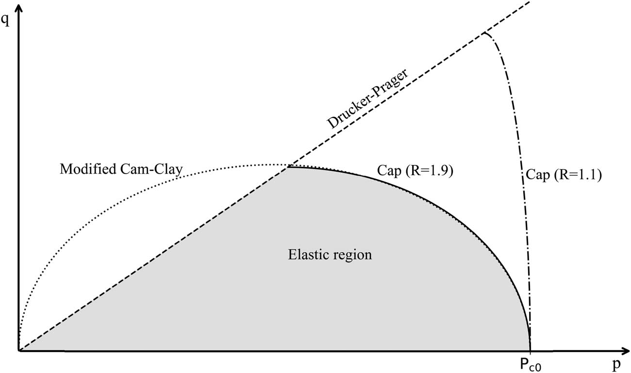
Figure 4
Cap model yield surface.
Source: Author’s contribution.

Figure 5
Unfitness and its mean (dashed) change during genetic algorithm calibration.
Source: Author’s contribution.
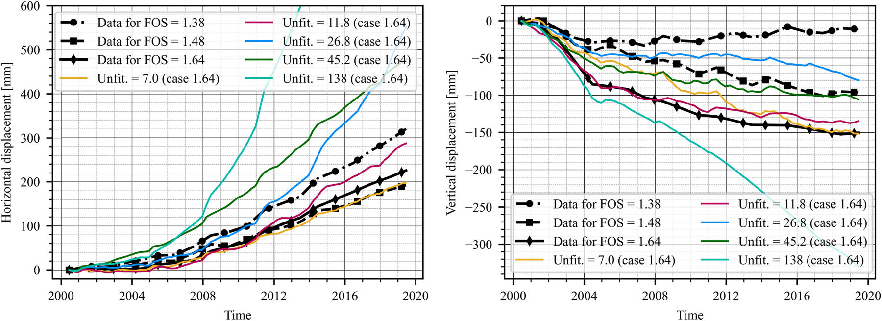
Figure 6
Match to horizontal (left) and vertical (right) displacement data of U2 gauge.
Source: Author’s contribution.
Table 3
Permissible ranges of parameters being calibrated.
| Material | Parameter | Min | Max |
|---|---|---|---|
| 1A | E (MPa) | 15.0 | 60.0 |
| ν (−) | 0.20 | 0.40 | |
| k x (m/s) | 1 × 10⁻¹¹ | 1 × 10⁻⁸ | |
| k y (m/s) | 1 × 10⁻¹¹ | 1 × 10⁻⁸ | |
| P c0 (kPa) | 300 | 700 | |
| λ (−) | 0.05 | 0.15 | |
| R (−) | 1.2 | 2.0 | |
| c (kPa) | 10 | 15 | |
| φ (°) | 15 | 20 | |
| ME (−) | 5 | 13 | |
| 2B | E (MPa) | 60 | 100 |
| ν (−) | 0.20 | 0.40 | |
| k x (m/s) | 1 × 10⁻⁹ | 1 × 10⁻⁶ | |
| k y (m/s) | 1 × 10⁻⁹ | 1 × 10⁻⁶ | |
| P c0 (kPa) | 300 | 700 | |
| λ (−) | 0.05 | 0.15 | |
| R (−) | 1.2 | 2.0 | |
| c (kPa) | 15 | 20 | |
| φ (°) | 20 | 25 | |
| 3C | E (MPa) | 100 | 200 |
| ν (−) | 0.20 | 0.35 | |
| k x = k y (m/s) | 1 × 10⁻⁶ | 1 × 10⁻⁴ | |
| c (kPa) | 3 | 10 | |
| φ (°) | 26 | 36 | |
| Dykes | E (MPa) | 70 | 120 |
| ν (−) | 0.20 | 0.35 | |
| Beaches | E (MPa) | 30 | 70 |
| ν (−) | 0.2 | 0.4 | |
| k x (m/s) | 1 × 10⁻⁷ | 1 × 10⁻⁵ | |
| k y (m/s) | 1 × 10⁻⁷ | 1 × 10⁻⁵ | |
| Sediments | E (MPa) | 10 | 30 |
| ν (−) | 0.2 | 0.4 | |
| k x = k y (m/s) | 1 × 10⁻⁹ | 1 × 10⁻⁶ |
Source: Author’s contribution.
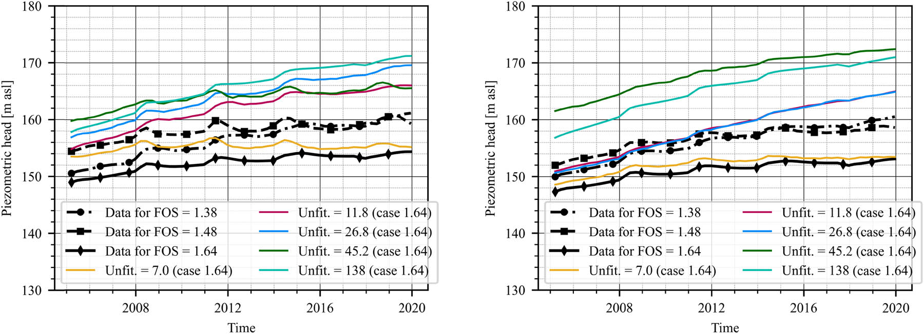
Figure 7
Match to piezometric data of P2 (left) and P3 (right) gauges.
Source: Author’s contribution.
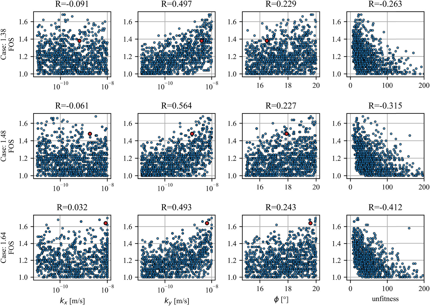
Figure 8
Relationships between FOS and parameters or unfitness; red dot indicates true values of FOS and parameters, and R is Pearson coefficient.
Source: Author’s contribution.
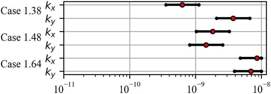
Figure 9
Hydraulic conductivity ranges assumed to be correct identification.
Source: Author’s contribution.
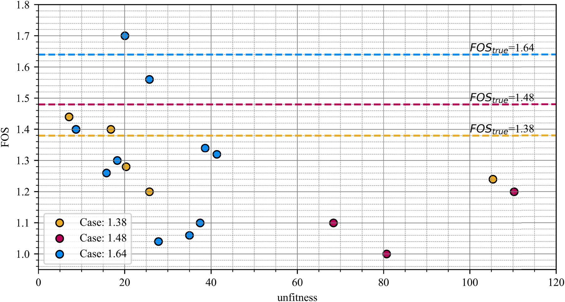
Figure 10
FOS values for correctly identified hydraulic conductivity and angle of internal friction.
Source: Author’s contribution.
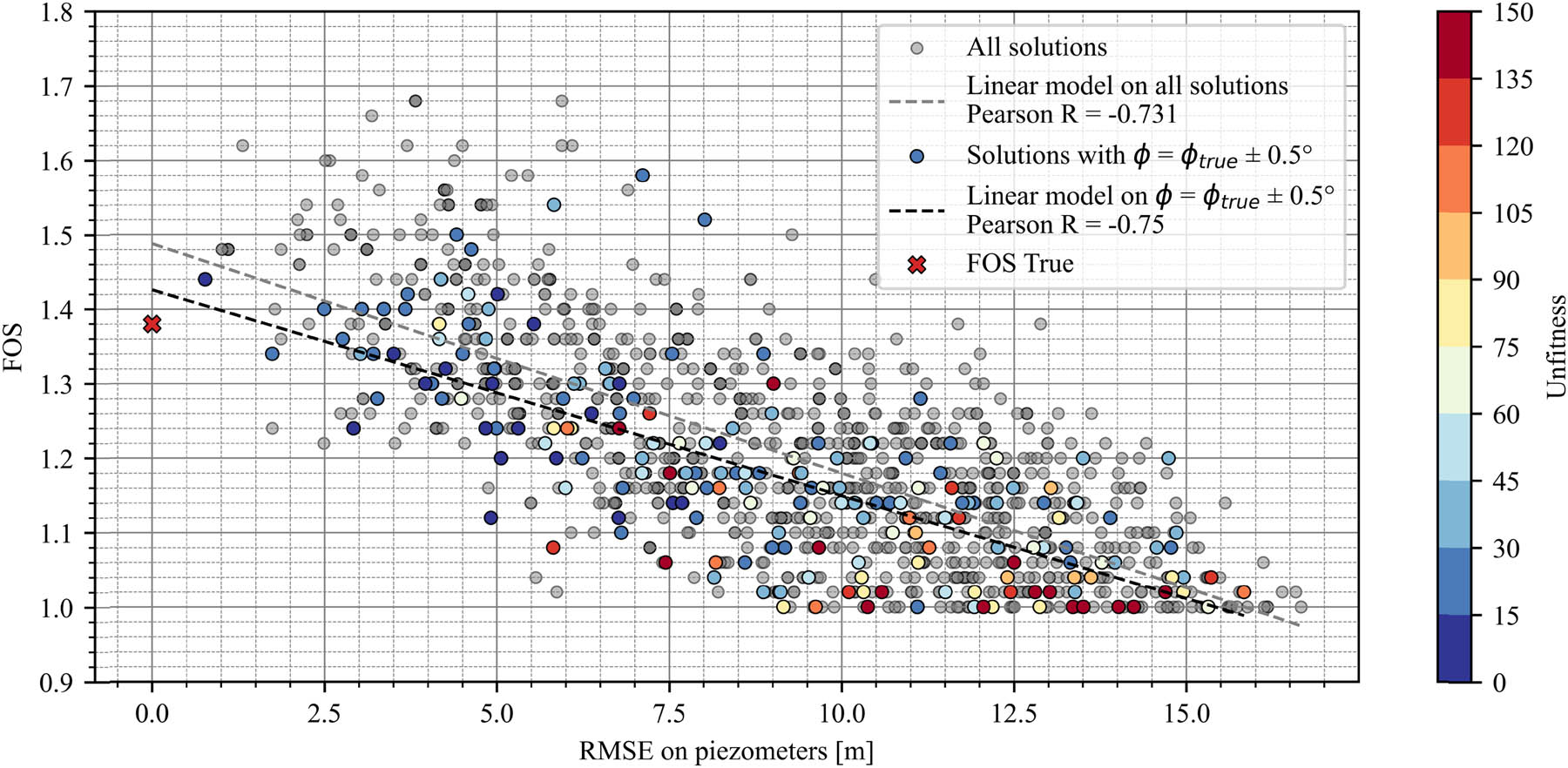
Figure 11
Relationship between piezometer fit (expressed as RMSE) and FOS in case 1.38.
Source: Author’s contribution.
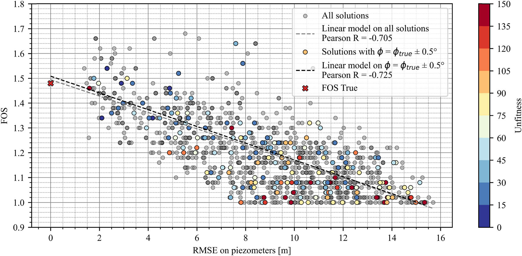
Figure 12
Relationship between piezometer fit (expressed as RMSE) and FOS in case 1.48.
Source: Author’s contribution.
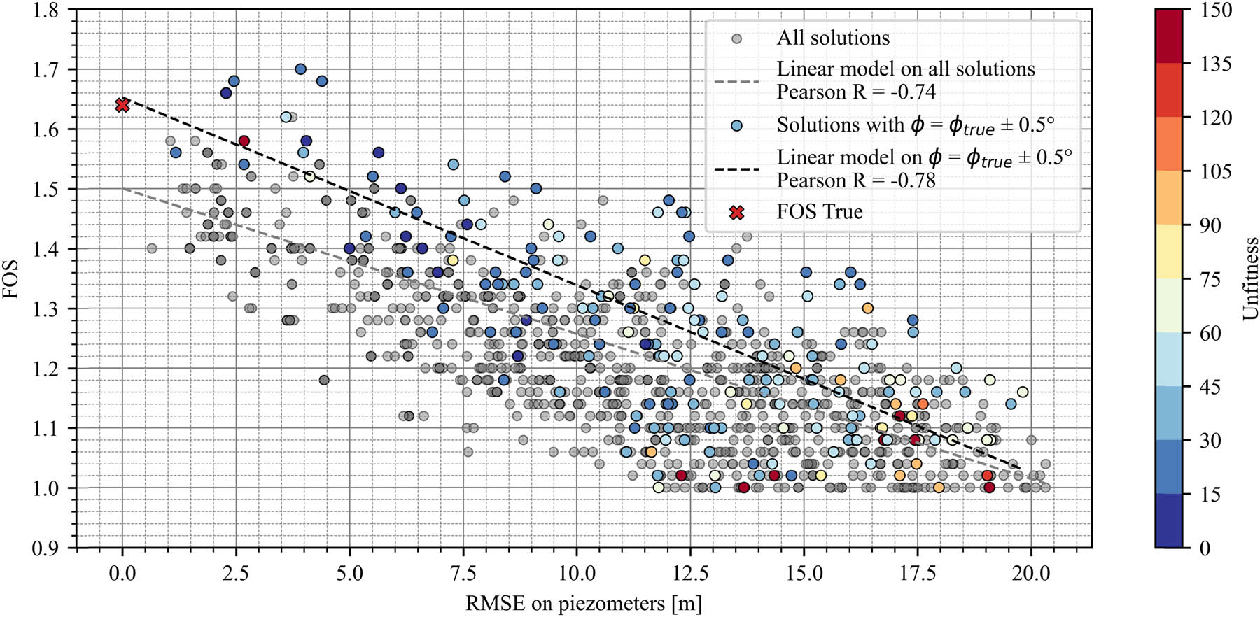
Figure 13
Relationship between piezometer fit (expressed as RMSE) and FOS in case 1.64.
Source: Author’s contribution.
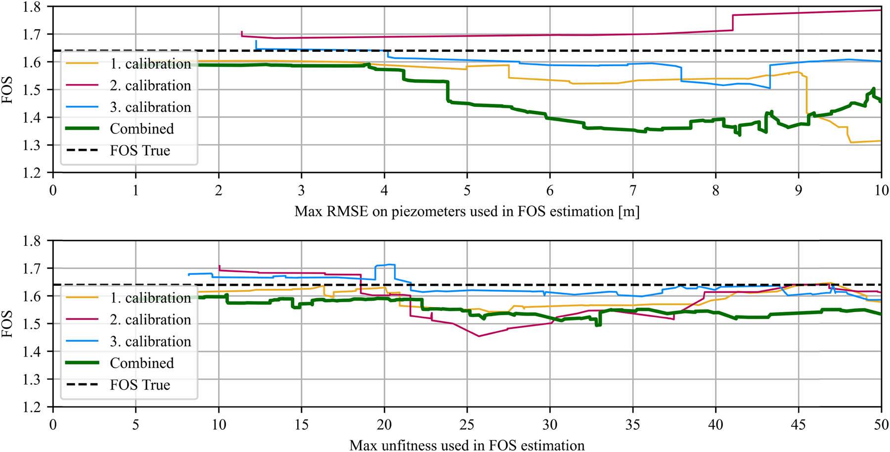
Figure 14
FOS estimated using individuals with value above RMSE calculated on piezometers (above) or unfitness (below).
Source: Author’s contribution.