
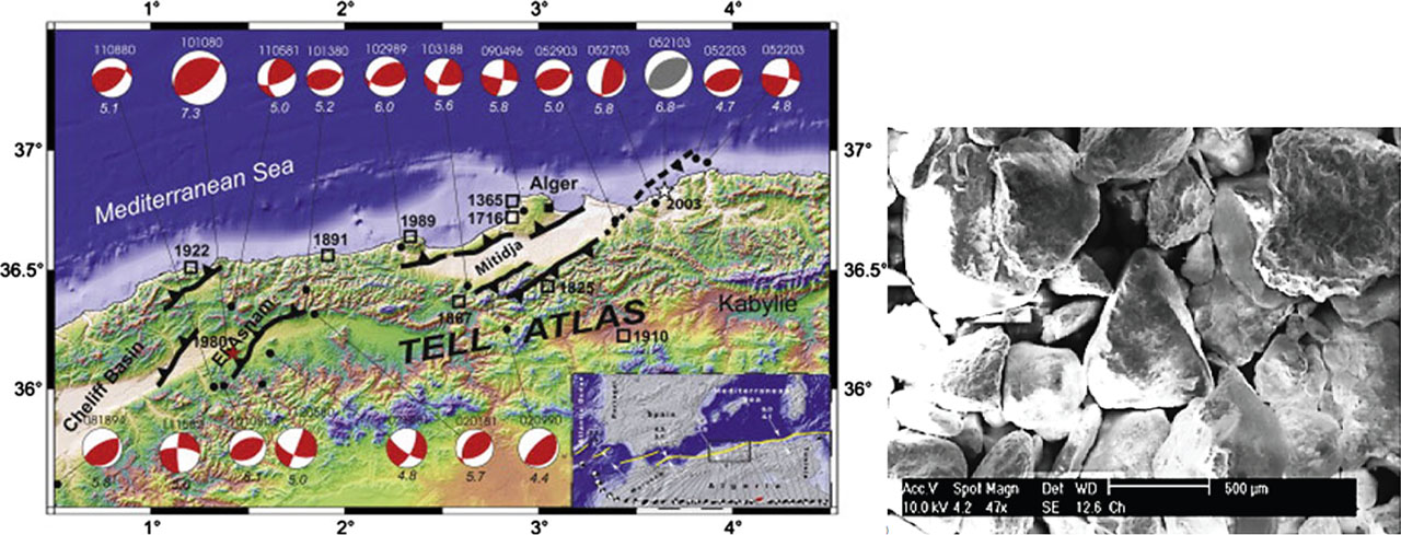
Figure 1:
Chlef sand under study: (a) situation of Chlef (formerly El Asnam) region [42] and (b) sand visualised using a scanning electron microscope [21].
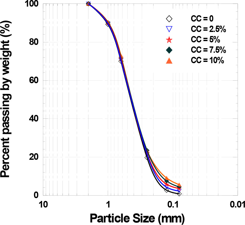
Figure 2:
Size distribution of the particles of the tested materials [25]. CC, cement content.
Table 1:
Physical characteristics of Chlef sand.
| Materials used | CC (%) | GS | D50 (mm) | CU | CCURV | emin | emax |
|---|---|---|---|---|---|---|---|
| Chlef sand | 0 | 2.7 | 0.45 | 2.34 | 1.39 | 0.582 | 0.873 |
Table 2:
Chemical and mineralogical compositions of the cement [25].
| Chemical compositions (%) | Mineralogical compositions (%) | ||
|---|---|---|---|
| SiO2 | 20.58 | C3S | 57.79 |
| Al2O3 | 4.90 | ||
| Fe2O3 | 4.70 | C2S | 20.47 |
| CaO | 62.8 | ||
| SO3 | 2.28 | C3A | 7.20 |
| MgO | 0.53 | ||
| K2O | 0.42 | C4AF | 11.49 |
| Na2O | 0.12 | ||
| Free lime | 2.17 | ||
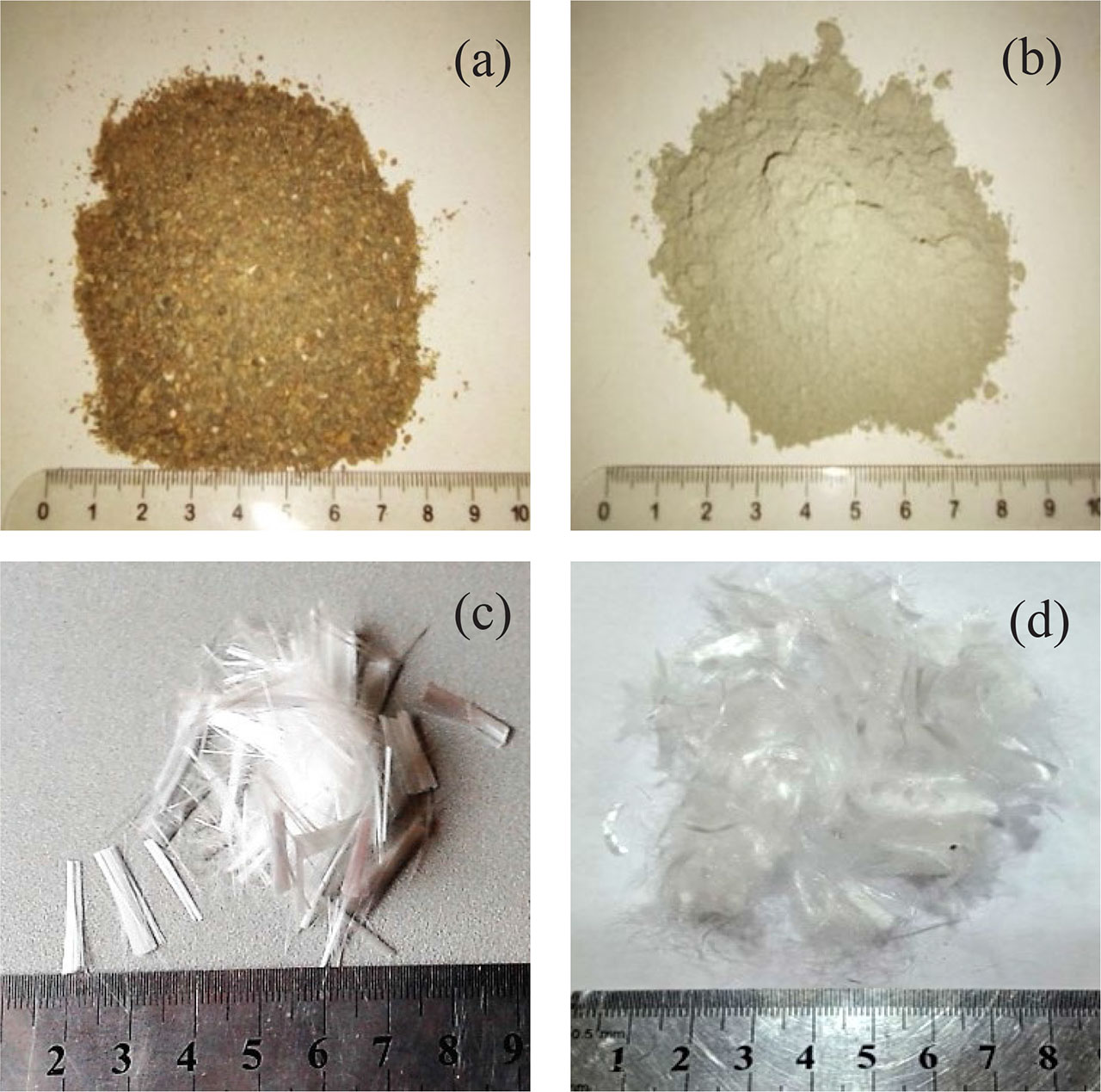
Figure 3.
Materials used: (a) sand, (b) cement, (c) glass fibres and (d) polypropylene fibres.
Table 3:
Physicomechanical characteristics of the glass fibres used [29].
| Name | Unit | Glass fibres | Polypropylene fibres |
|---|---|---|---|
| Colour | – | White | White |
| Width | mm | 0.12 | 0.03 |
| Thickness | mm | 0.013 | – |
| Specific gravity | – | 2.62 | 0.96 |
| Specific weight | g/m2 | 300 | – |
| Tensile strength | MPa | 2500 | 500–750 |
| Poisson coefficient | – | 0.35 | – |
| Shear modulus | GPa | 29.2 | – |
| Young modulus | GPa | 73 | 2.9–3.8 |
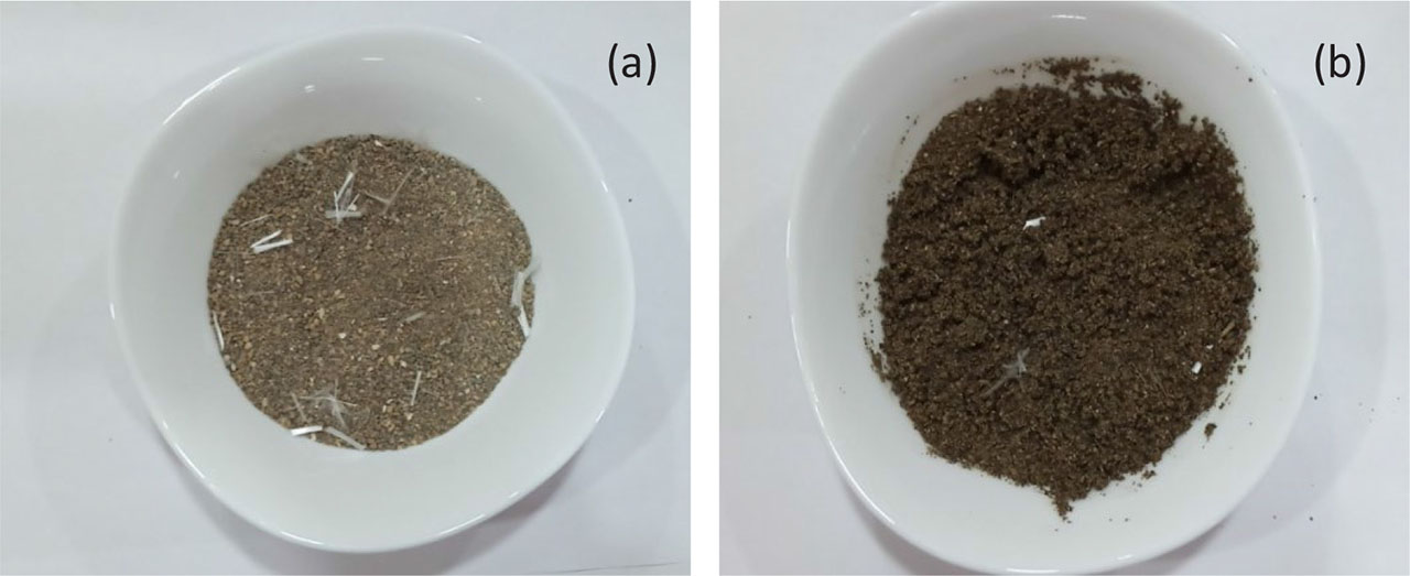
Figure 4:
Sample preparation: (a) fibre-reinforced mixtures: dry state; and (b) fibre-reinforced mixtures: wet state with a water content of 10%.
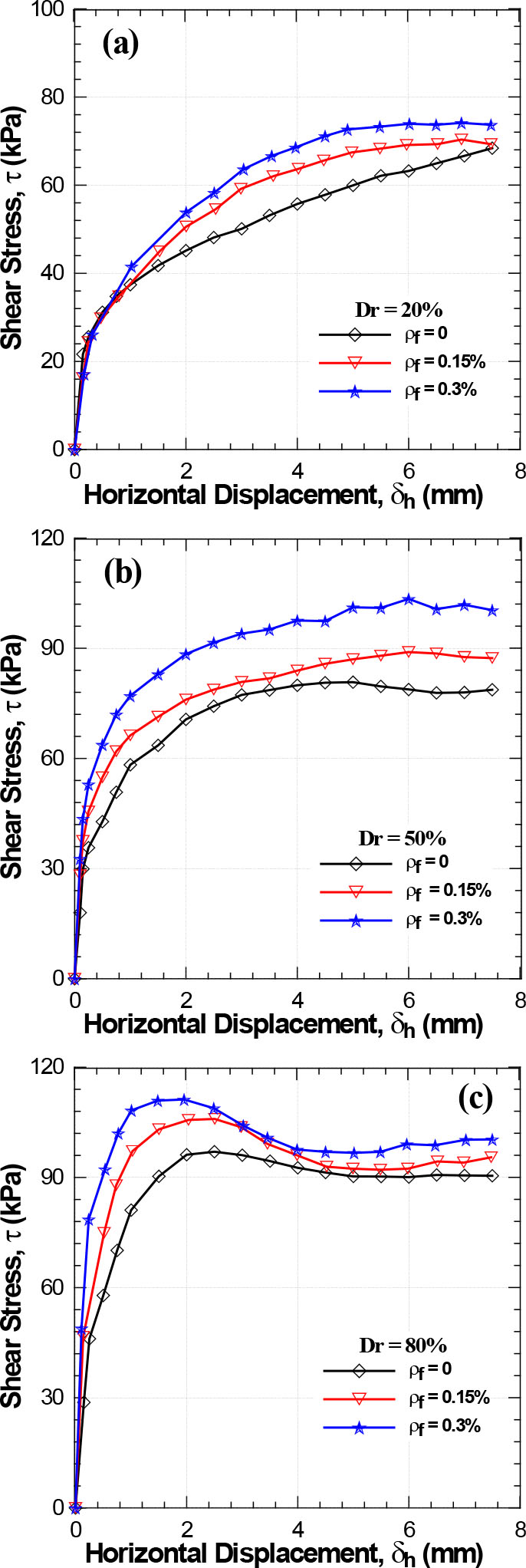
Figure 5:
Effect of glass fibre content on sand shear strength (σn = 100 kPa): (a) Dr = 20%, (b) Dr = 50% and (c) Dr = 80%. Dr, relative density.
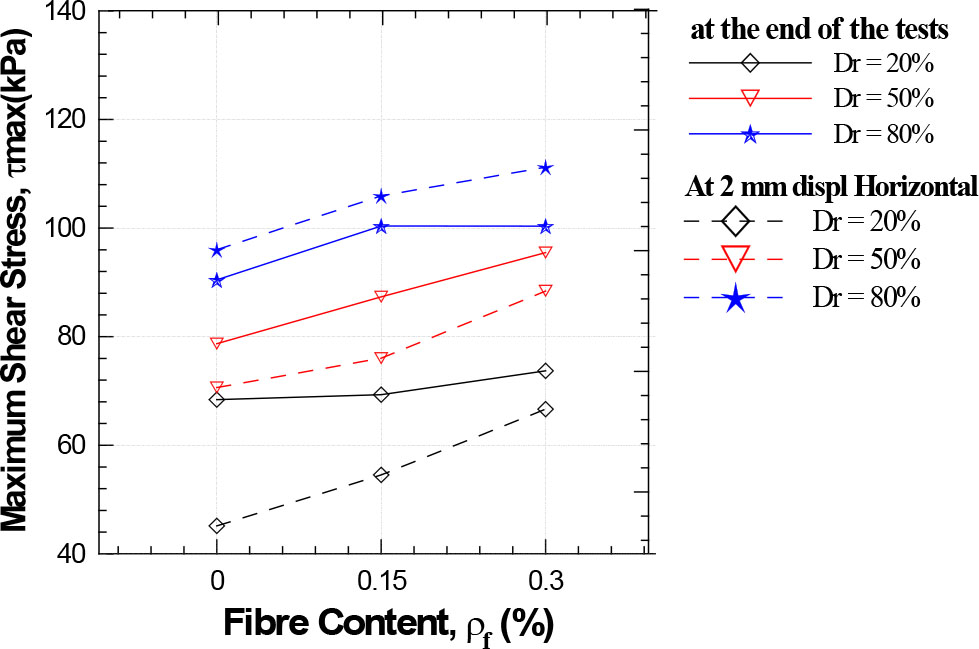
Figure 6:
Effect of relative density on shear strength in glass fibre-reinforced sand. Dr, relative density.
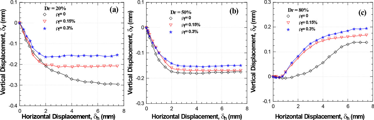
Figure 7:
Effect of glass fibre content on vertical displacement (σn = 100 kPa): (a) Dr = 20%, (b) Dr = 50% and (c) Dr = 80%. Dr, relative density.
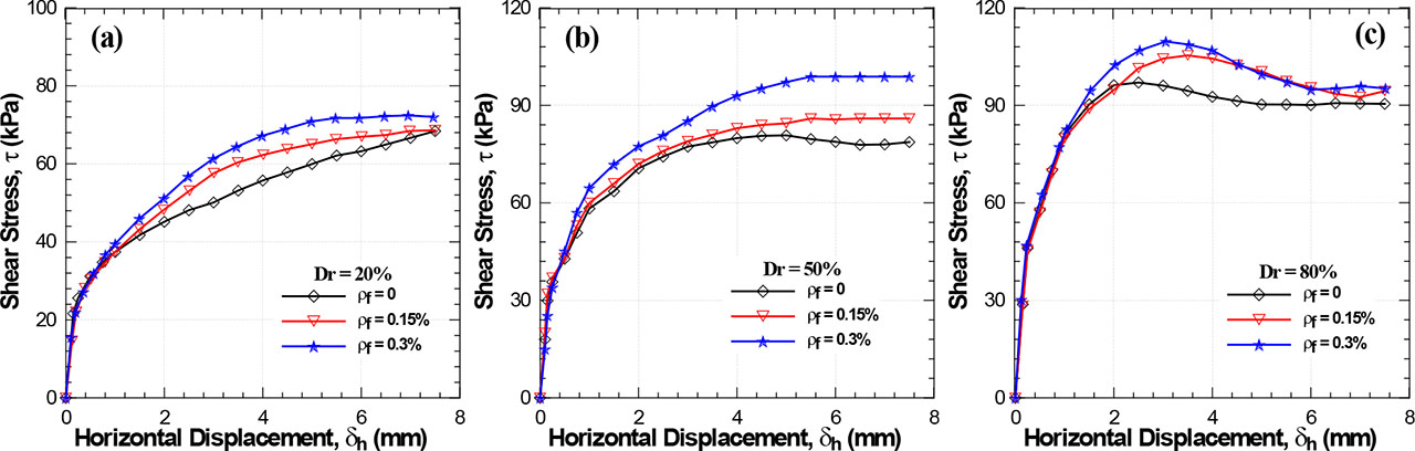
Figure 8:
Effect of polypropylene fibre content on sand shear strength (σn = 100 kPa): (a) Dr = 20%, (b) Dr = 50% and (c) Dr = 80%. Dr, relative density.
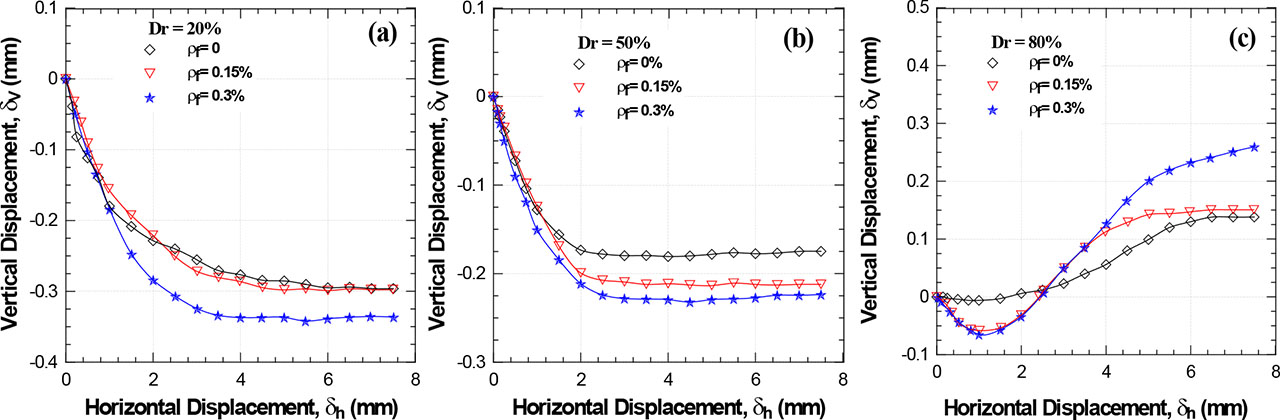
Figure 9:
Effect of polypropylene fibre content on vertical deformation of sand (σn = 100 kPa): (a) Dr = 20%, (b) Dr = 50% and (c) Dr = 80%. Dr, relative density.
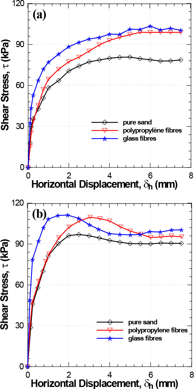
Figure 10:
Comparison between glass fibres and polypropylene fibres and their effect on stress/strain curves (σn = 100 kPa and ρf = 0.3%): (a) Dr = 50% and (b) Dr = 80%. Dr, relative density.
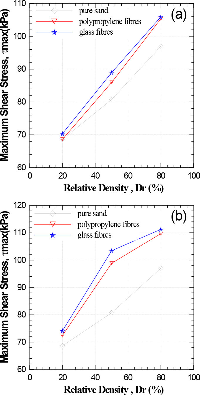
Figure 11:
Effect of different fibre types on maximum shear strength: (a) fibre content = 0.15% and (b) fibre content = 0.3%.
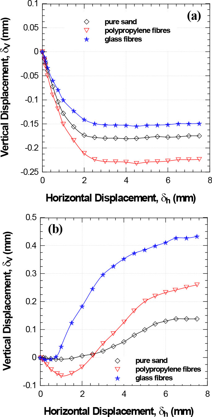
Figure 12:
Comparison between glass fibres and polypropylene fibres in terms of variations in vertical displacements (σn = 100 kPa and ρf = 0.3%): (a) Dr = 50% and (b) Dr = 80%. Dr, relative density.
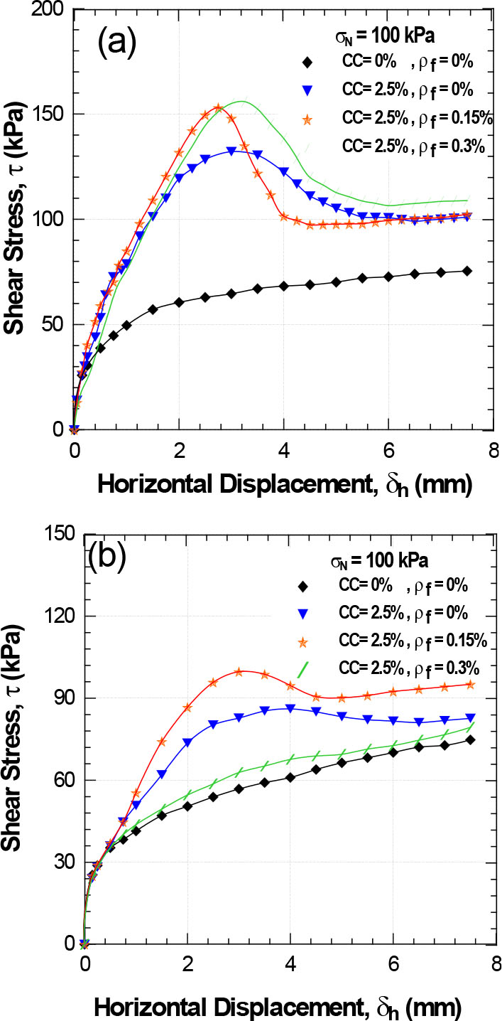
Figure 13:
Effect of glass fibre content on shear strength of fibre-cemented sand (CC = 2.5%, σn = 100 kPa, w = 10%): (a) Dr = 80% and (b) Dr = 50%. CC, cement content; Dr, relative density.
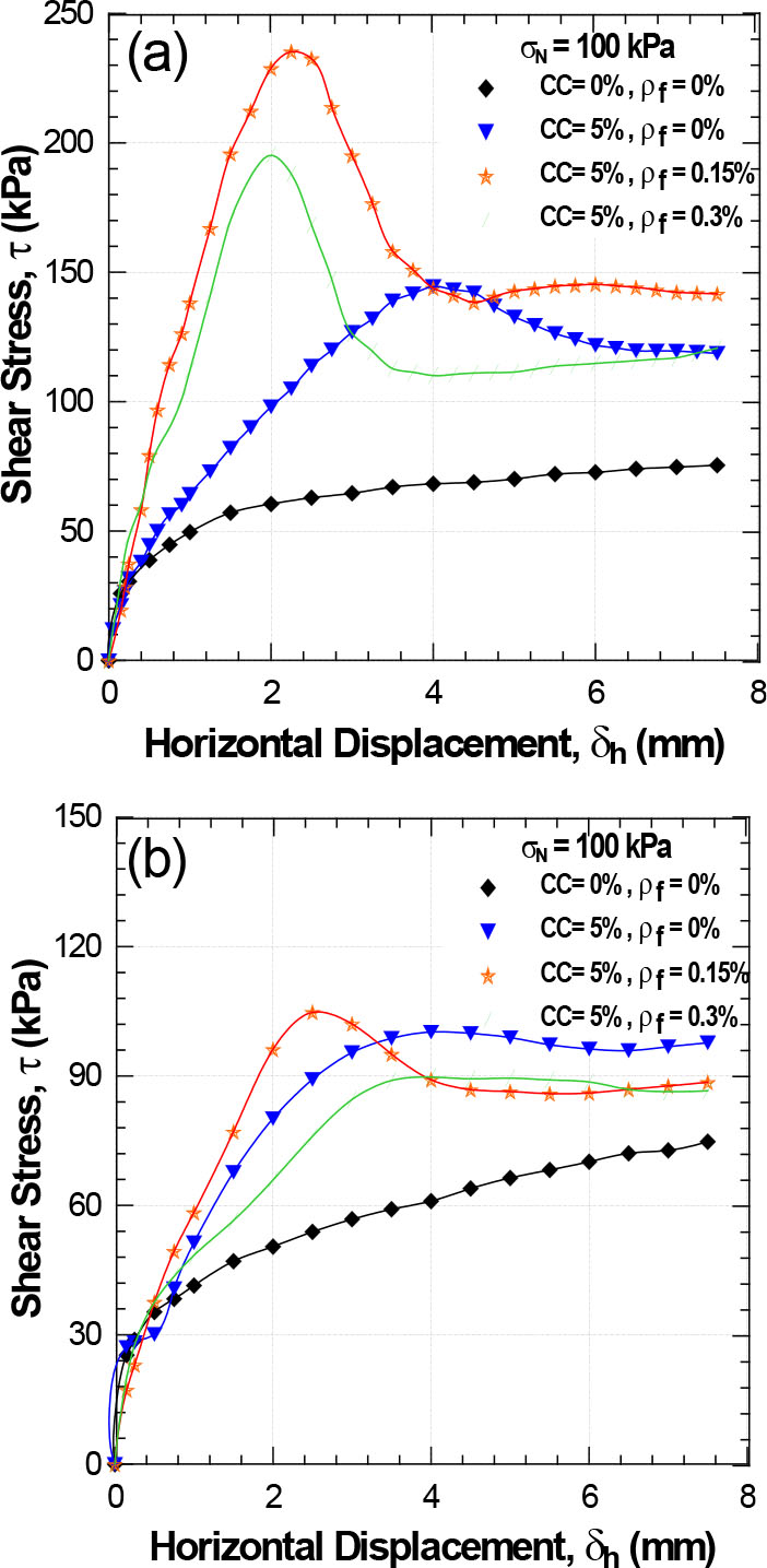
Figure 14:
Effect of glass fibre content on shear strength of fibre-cemented sand (CC = 5%, σn = 100 kPa, w = 10%): (a) Dr = 80% and (b) Dr = 50%. CC, cement content; Dr, relative density.
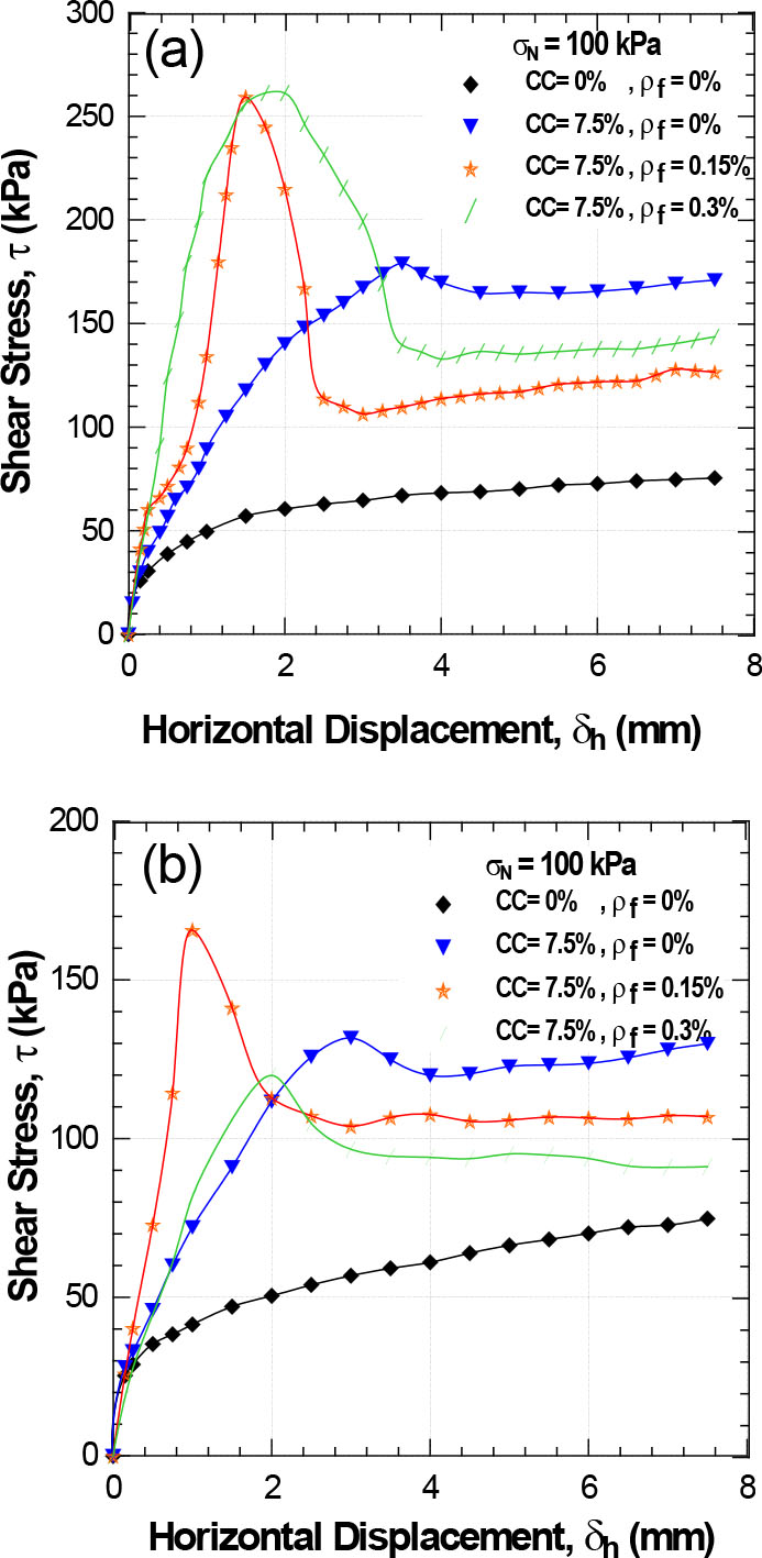
Figure 15:
Effect of glass fibre content on shear strength of cemented sand (CC = 7.5%, σn = 100 kPa, w = 10%): (a) Dr = 80% and (b) Dr = 50%. CC, cement content; Dr, relative density.
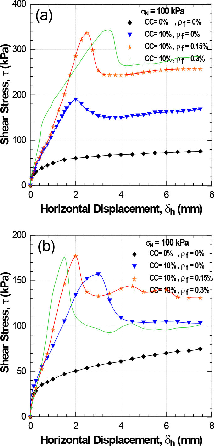
Figure 16:
Effect of glass fibre content on shear strength of cemented sand (CC = 10%, σn = 100 kPa, w = 10%): (a) Dr = 80% and (b) Dr = 50%. CC, cement content; Dr, relative density.
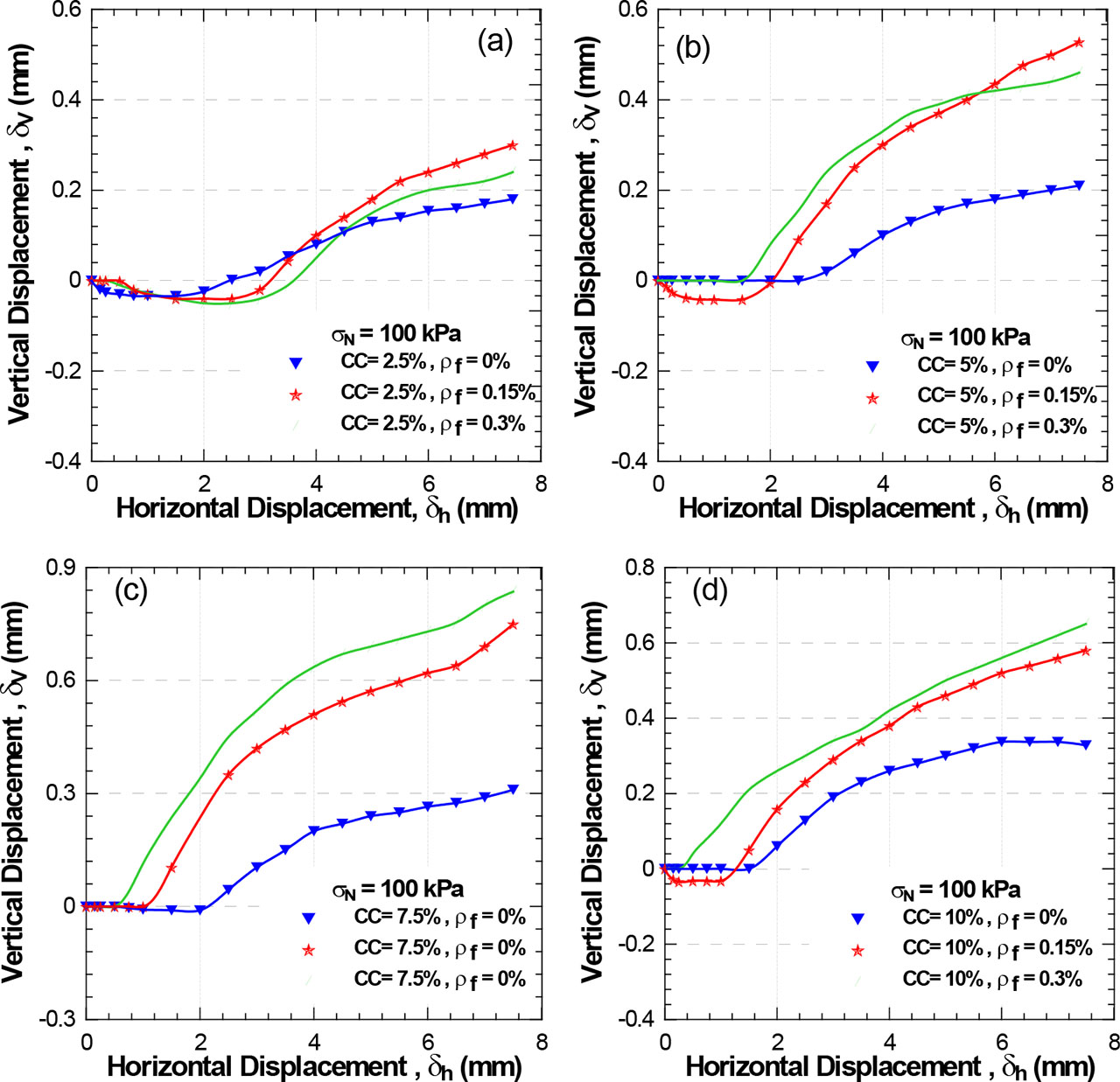
Figure 17:
Effect of glass fibre content on vertical displacement of cemented sand (σn = 100 kPa, w = 10%, Dr = 80%): (a) CC = 2.5%, (b) CC = 5%, (c) CC = 7.5% and (d) CC = 10%. CC, cement content; Dr, relative density.
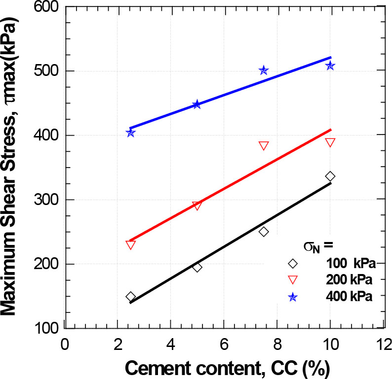
Figure 18:
Variation in maximum shear strength according to cement content (Dr = 80%, ρf = 0.15%). Dr, relative density.
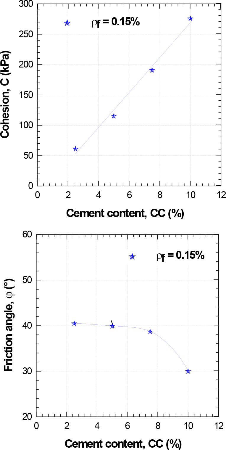
Figure 19:
Effect of cement content on glass fibre-reinforced sand–cement mixtures (Dr = 80%): (a) variation in cohesion and (b) variation in internal friction angle. Dr, relative density.