
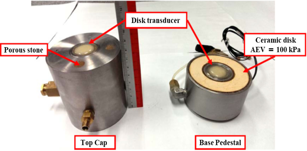
Figure 1:
Modified pedestal and top cap of triaxial apparatus, fitted with disk-type piezoelectric transducers at their respective centers.
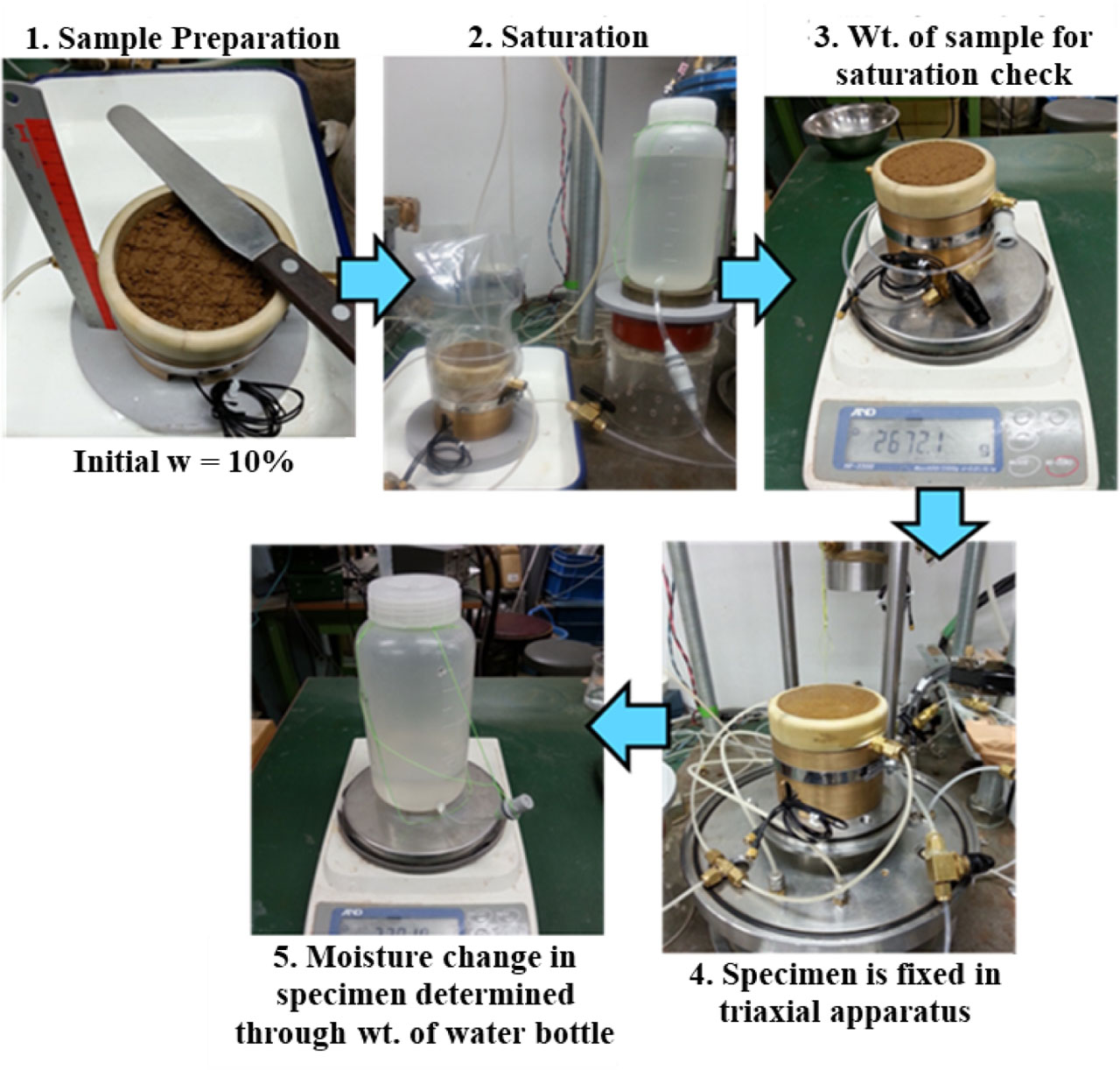
Figure 2:
Specimen preparation and saturation.
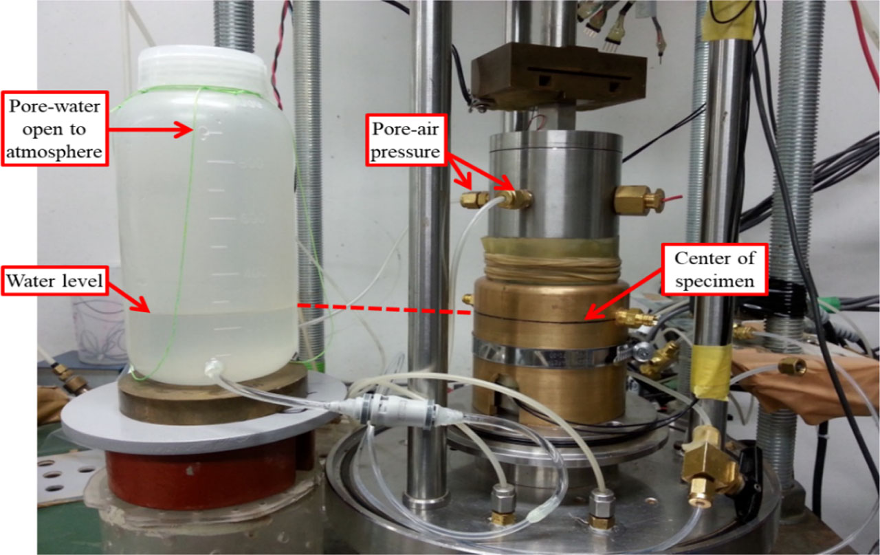
Figure 3:
Water injection/drainage setup.
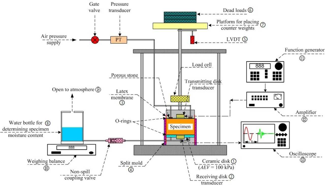
Figure 4:
Schematic layout of modified SWCC wave velocity apparatus.
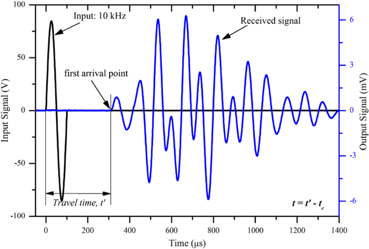
Figure 5:
Travel time determination of compression wave signals.
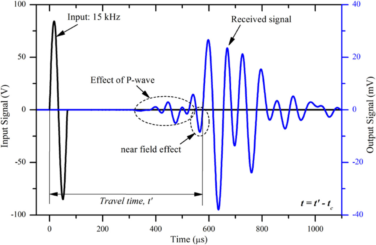
Figure 6:
Travel time determination of shear wave signals.
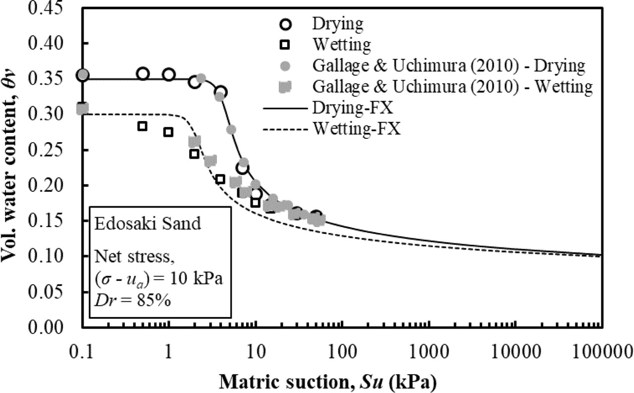
Figure 7:
Soil water characteristic curve (SWCC) of Edosaki sand.
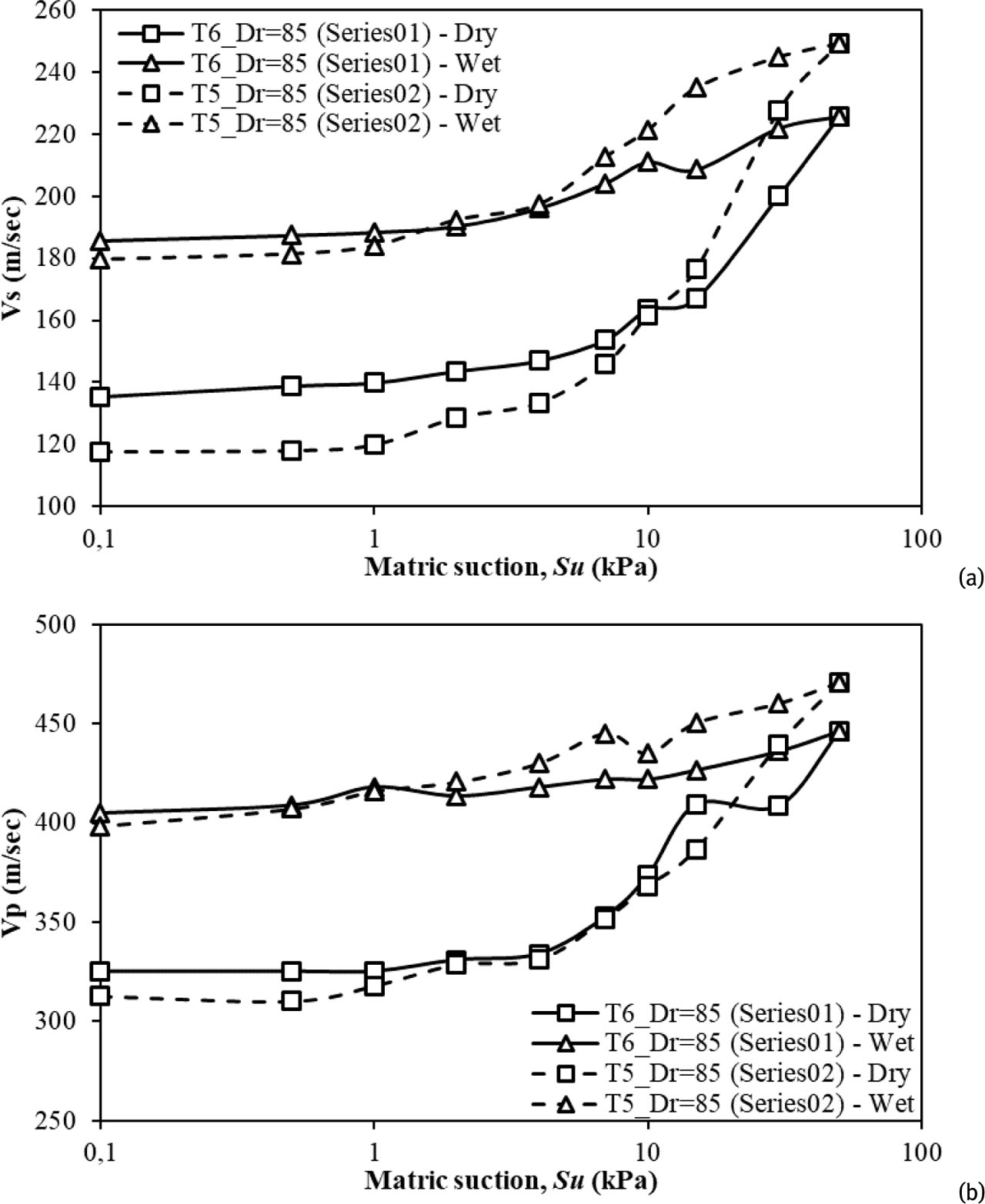
Figure 8:
Relationship b/w suction and (a) shear wave velocity, (b) compression wave velocity.
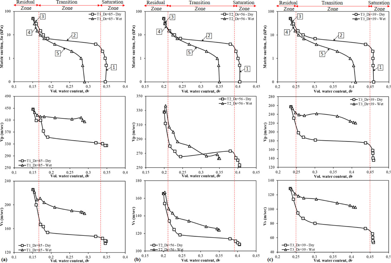
Figure 9:
Effect of variation in relative density on matric suction, shear wave velocity, and compression wave velocities with volumetric water content.
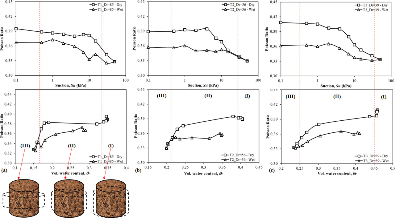
Figure 10:
Measured Poisson’s ratio versus matric suction and volumetric water content.
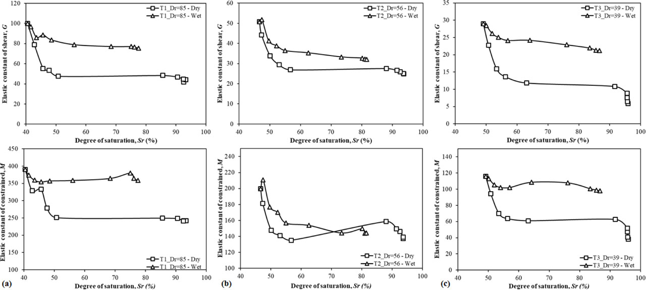
Figure 11:
Relation between soil moduli and degree of saturation.