
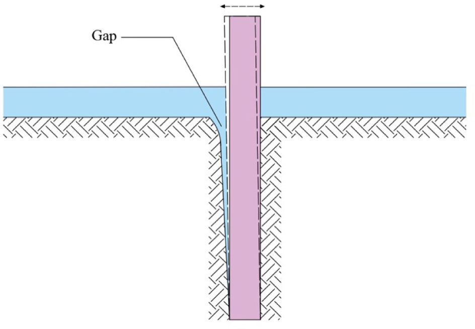
Figure 1
Pile due to cyclic load.
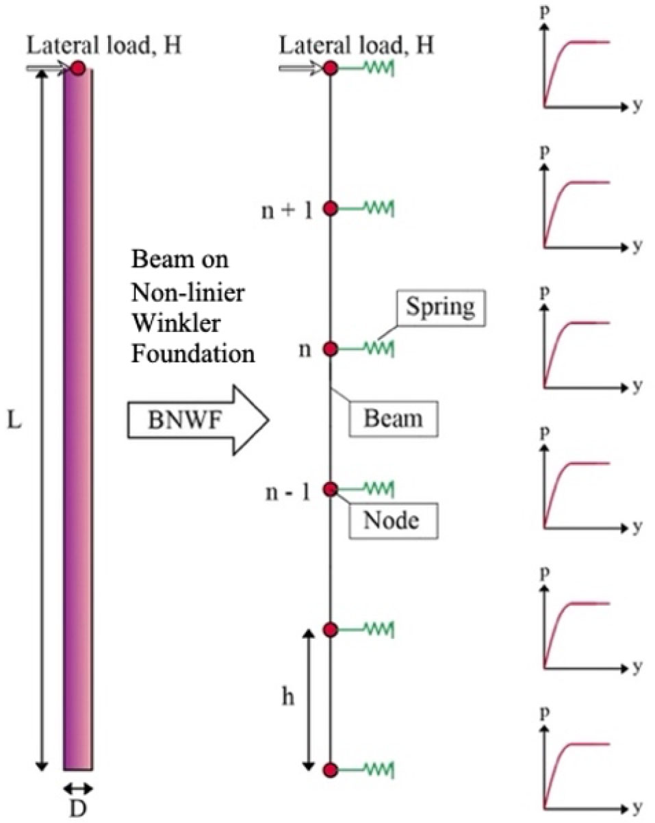
Figure 2
The p–y curve based on the Winkler's model.
Table 1
N60 and Vs values derived from SPT data.
| Parameters | Methods | Unit | Values | ||||
| Soil classification | MH | MH | SC–SM | SC–SM | CL | ||
| Depth | m | 0.00–5.50 | 5.50–8.50 | 8.50–11.50 | 11.50–14.50 | 14.50–17.50 | |
| 12 | 11 | 14 | 28 | 34 | |||
| Vs | Maheswari et al. [13] | m/s | 176.67 | 172.18 | 194.68 | 233.75 | 243.14 |
| Hasancebi and Ulusuay in Hammam and Eliwa [12] | 204.80 | 200.34 | 208.53 | 249.35 | 269.12 | ||
| Tsiambaos and Sabatakakis [14] | 237.39 | 230.90 | 209.41 | 269.15 | 334.70 | ||
| Parameters | Methods | Unit | Values | ||||
| Soil classification | MH | SM | SM | MH | CL–ML | ||
| Depth | m | 17.50–20.00 | 20.00–23.50 | 23.50–26.50 | 26.50–29.50 | 29.50–30.00 | |
| 44 | 68 | 55 | 54 | 55 | |||
| Vs | Maheswari et al. [13] | m/s | 263.66 | 296.06 | 279.39 | 279.36 | 241.78 |
| Hasancebi and Ulusuay in Hammam and Eliwa [12] | 288.43 | 314.14 | 296.83 | 303.06 | 305.09 | ||
| Tsiambaos and Sabatakakis [14] | 365.18 | 372.23 | 343.76 | 388.62 | 456.36 | ||
[i] Note: MH = Elastic silt ; SC–SM = Silty, clayey sand ; CL = Lean clay ; SM = Silty sand; CL–ML = Sandy silty clay ;
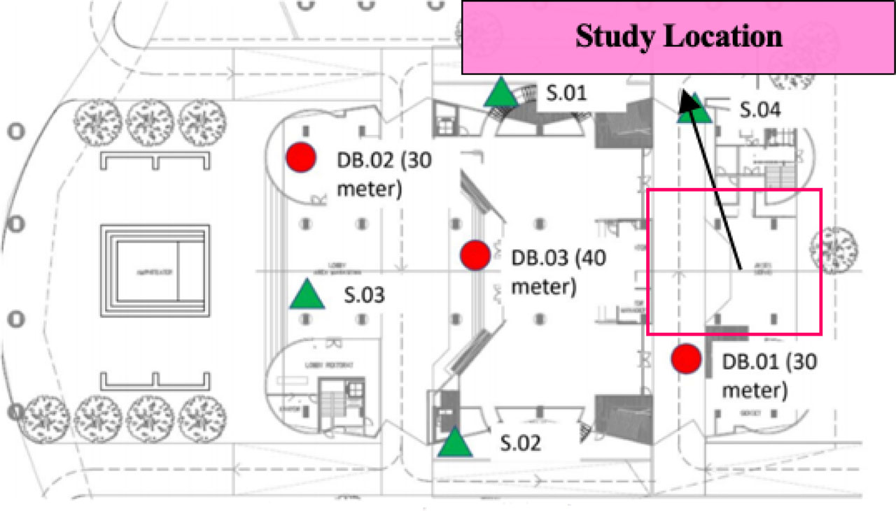
Figure 3
Site of the study.
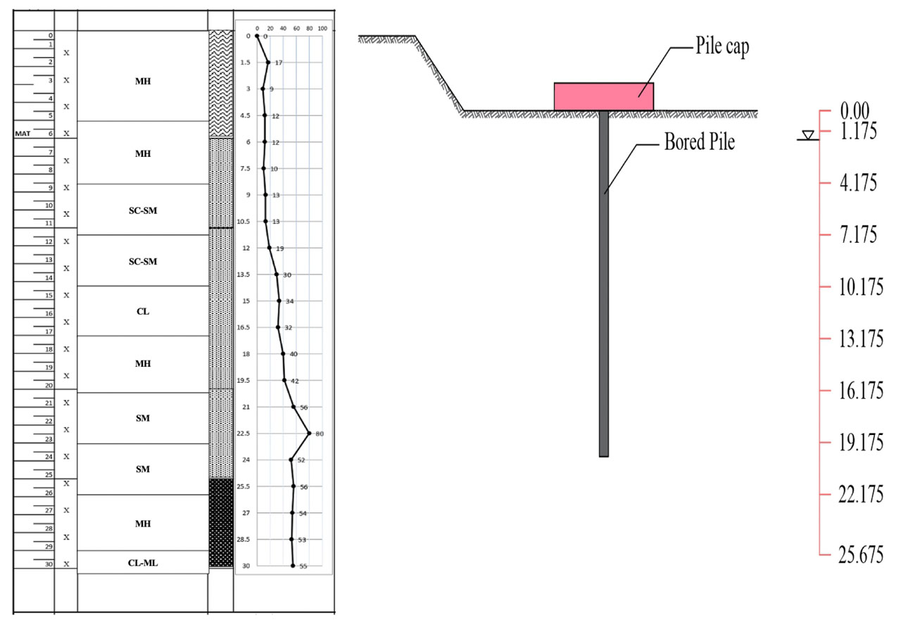
Figure 4
Bore pile elevation.
Table 2
Modulus of elasticity.
| Parameters | Symbol | Unit | Values | ||||
| Soil classification | MH | MH | SC–SM | SC–SM | CL | ||
| Depth | m | 0.00–5.50 | 5.50–8.50 | 8.50–11.50 | 11.50–14.50 | 14.50–17.50 | |
| Shear modulus | Gmax1 | kN/m2 | 31,512.89 | 30,168.81 | 54,463.84 | 58,647.40 | 62,843.00 |
| Gmax2 | kN/m2 | 42,346.40 | 40,843.44 | 62,487.42 | 66,734.39 | 76,989.80 | |
| Gmax3 | kN/m2 | 56,897.20 | 54,258.68 | 63,015.42 | 77,752.24 | 119,082.54 | |
| Modulus of elasticity | Es1 | kN/m2 | 80,257.83 | 76,107.67 | 141,750.84 | 157,208.03 | 172,158.08 |
| Es2 | kN/m2 | 107,848.87 | 103,036.85 | 162,633.48 | 178,885.72 | 210,913.15 | |
| Es3 | kN/m2 | 144,907.24 | 136,879.86 | 164,007.69 | 208,419.75 | 326,226.01 | |
| Parameters | Symbol | Unit | Values | ||||
| Soil classification | MH | SM | SM | MH | CL–ML | ||
| Depth | m | 17.50–20.00 | 20.00–23.50 | 23.50–26.50 | 26.50–29.50 | 29.50–30.00 | |
| Shear modulus | Gmax1 | kN/m2 | 71,347.32 | 137,818.78 | 132,539.58 | 81,007.64 | 66,740.49 |
| Gmax2 | kN/m2 | 85,382.60 | 155,159.96 | 149,607.27 | 95,333.66 | 106,266.07 | |
| Gmax3 | kN/m2 | 136,865.04 | 217,852.44 | 200,658.77 | 156,762.39 | 237,768.36 | |
| Modulus of elasticity | Es1 | kN/m2 | 199,772.48 | 385,892.57 | 371,110.81 | 226,821.40 | 186,873.38 |
| Es2 | kN/m2 | 239,071.29 | 434,447.88 | 418,900.34 | 266,934.24 | 297,544.98 | |
| Es3 | kN/m2 | 383,222.10 | 609,986.82 | 561,844.55 | 438,934.70 | 665,751.40 | |
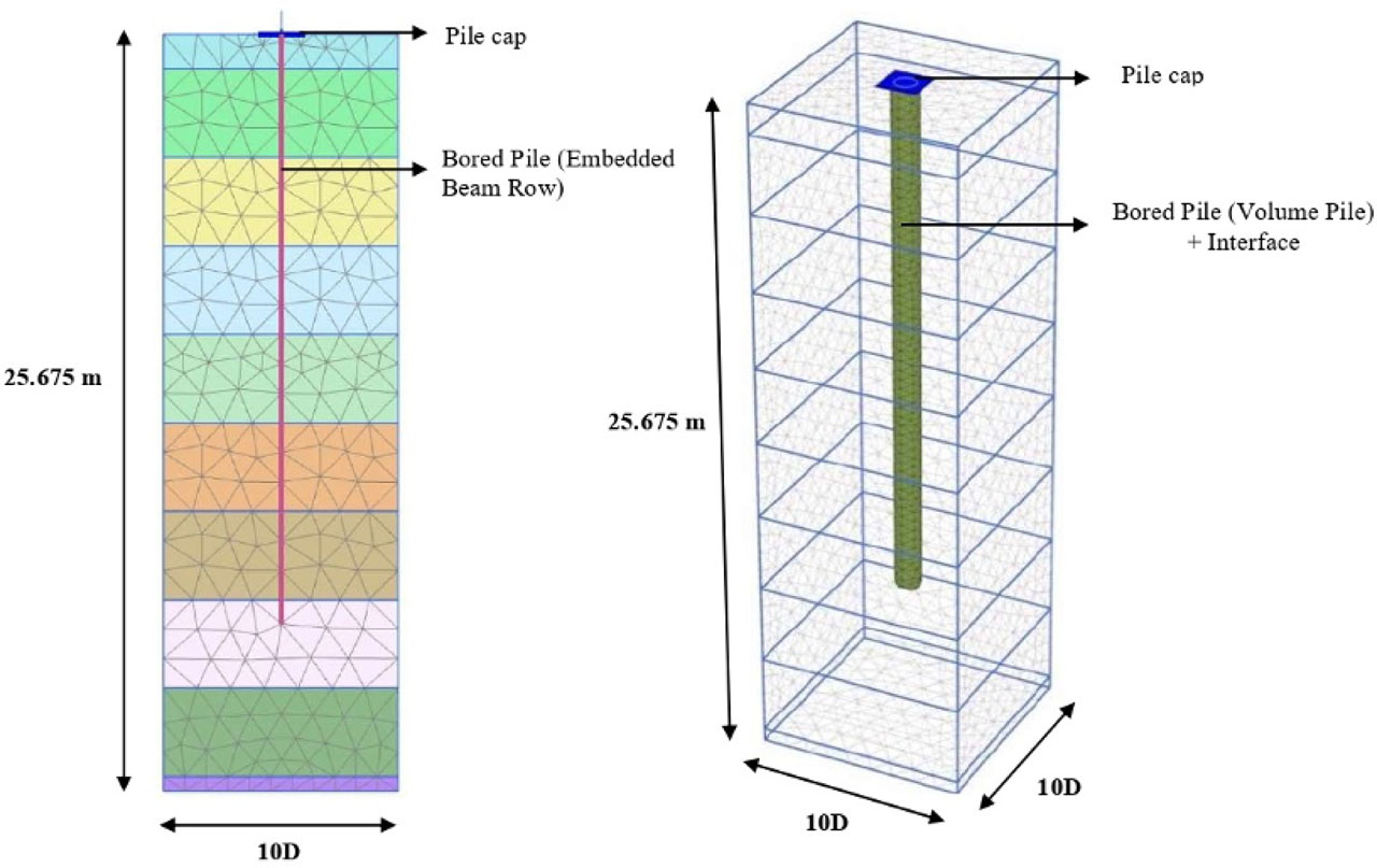
Figure 5
Pile modeling: (a) 2D finite element (b) 3D finite element.
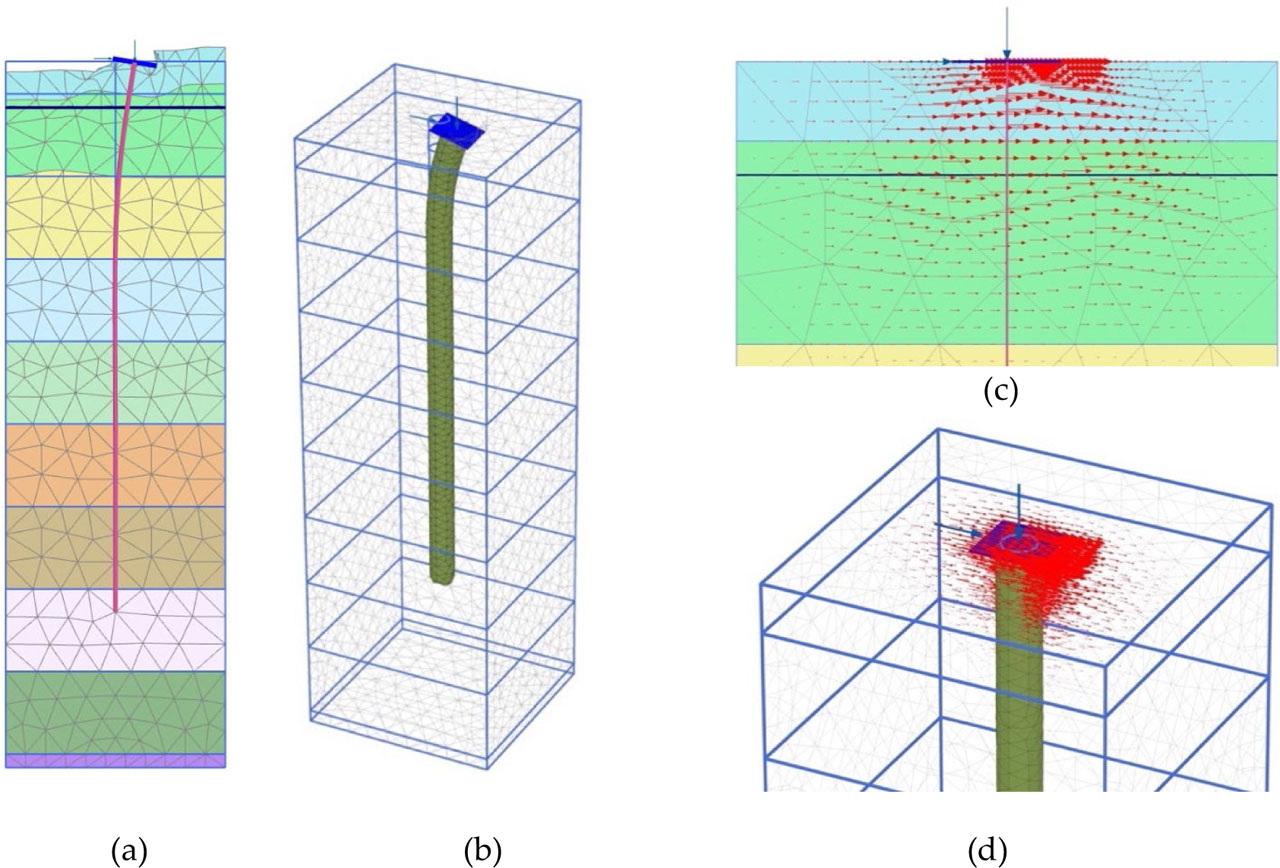
Figure 6
(a) Failure mechanism of 2D single pile. (b) failure mechanism of 3D single pile. (c) vector direction of 2D single pile. (d) vector direction of 3D single pile.
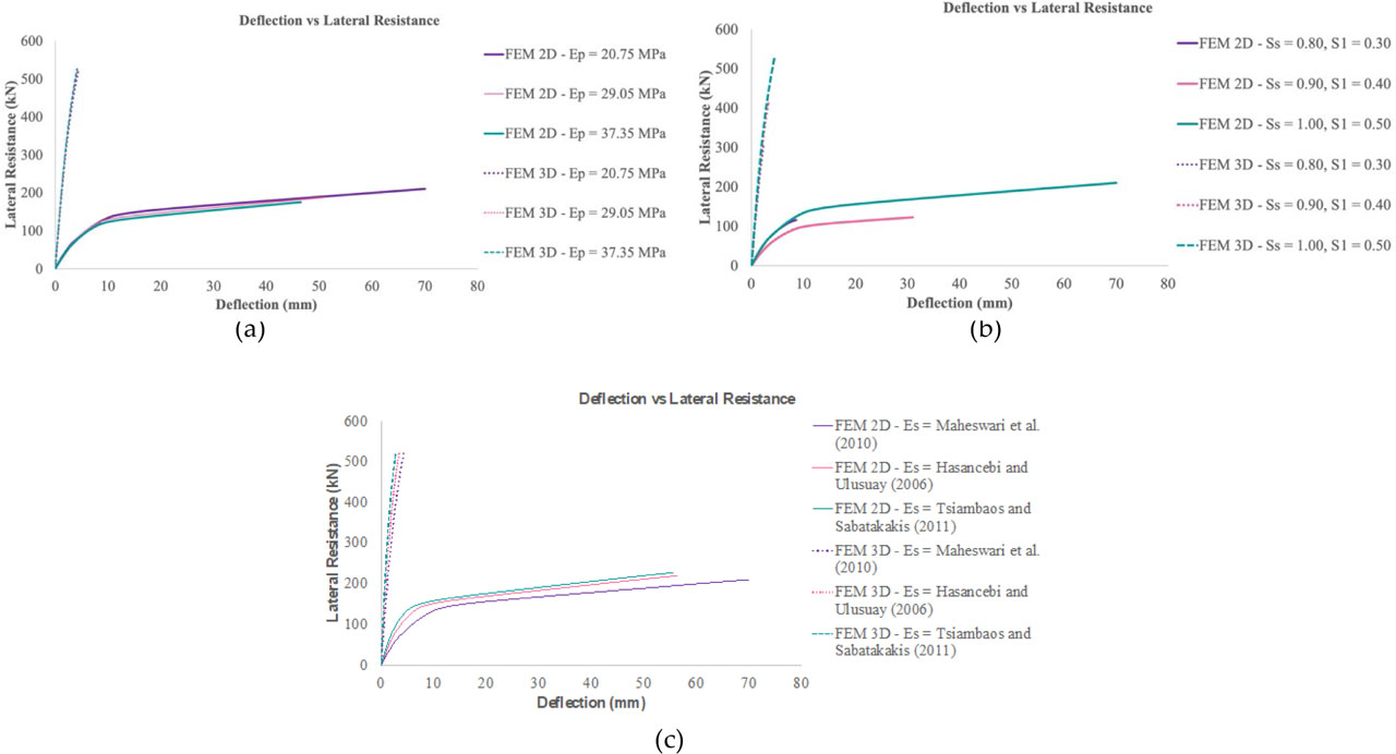
Figure 7
Lateral load capacity versus deflection: (a) combination lateral loads effect, (b) pile stiffness effect, (c) soil stiffness effect.
Table 3
The difference in lateral resistance with the FEM 3D.
| Lateral resistance (kN) | Difference in lateral resistance with FEM 3D (%) | ||
|---|---|---|---|
| FEM 2D | FEM 3D | ||
| Combination lateral loads effect | |||
| PS1 | 115.808 | 304.663 | 61.988 |
| PS2 | 118.323 | 414.567 | 71.459 |
| PS3 | 210.442 | 524.270 | 59.860 |
| Pile stiffness effect | |||
| Ep1 | 210.442 | 524.270 | 59.860 |
| Ep2 | 187.449 | 525.274 | 64.314 |
| Ep3 | 175.958 | 526.043 | 66.551 |
| Soil stiffness effect | |||
| Es1 | 210.442 | 524.270 | 59.860 |
| Es2 | 219.603 | 522.476 | 57.969 |
| Es3 | 227.736 | 520.390 | 56.237 |
Table 4
The difference in deflection with the FEM 3D.
| Deflection (mm) | The difference in deflection with FEM 3D (%) | ||
|---|---|---|---|
| FEM 2D | FEM 3D | ||
| Combination lateral loads effect | |||
| PS1 | 8.646 | 2.417 | 72.044 |
| PS2 | 31.044 | 3.532 | 88.622 |
| PS3 | 70.132 | 4.972 | 92.911 |
| Pile stiffness effect | |||
| Ep1 | 70.132 | 4.972 | 92.911 |
| Ep2 | 50.969 | 4.808 | 90.567 |
| Ep3 | 46.492 | 4.692 | 89.909 |
| Soil stiffness effect | |||
| Es1 | 70.132 | 4.972 | 92.911 |
| Es2 | 56.430 | 3.939 | 93.020 |
| Es3 | 55.688 | 3.140 | 94.362 |
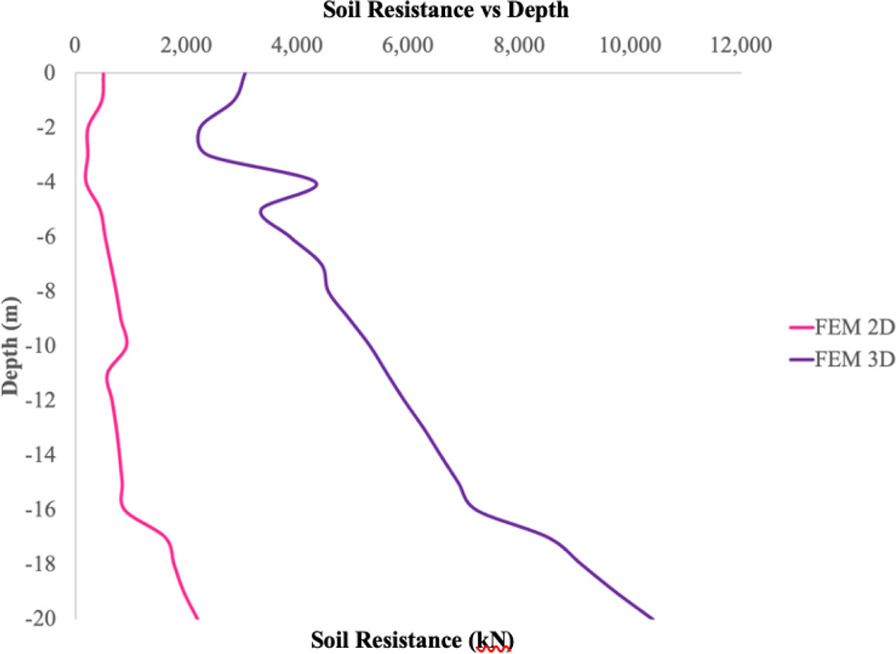
Figure 8
Lateral bearing capacity.
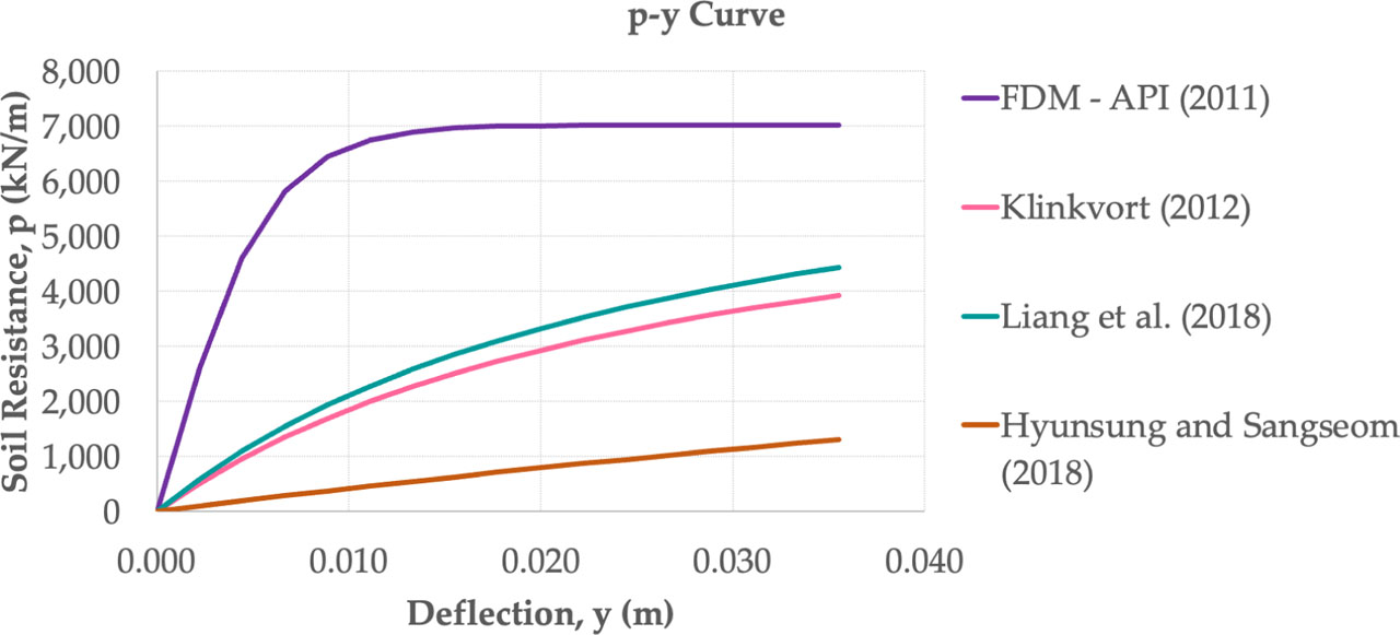
Figure 9
p–y curve.
Table 5
The difference in deflection with the FEM 3D.
| Lateral resistance (kN) | The difference in deflection with FEM 3D (%) | The difference in deflection with FEM 2D (%) | |
|---|---|---|---|
| FEM 3D | 10,410.00 | - | 81.220 |
| FEM 2D | 1,955.00 | 81.220 | - |
| FDM – API (2011) | 7,025.381 | 32.513 | 72.172 |
| Klinkvort (2012) | 3,931.621 | 62.232 | 50.275 |
| Liang et al. (2018) [10] | 4,441.177 | 57.337 | 55.980 |
| Hyunsung and Sangseom (2018) [11] | 1,306.272 | 87.452 | 33.183 |