
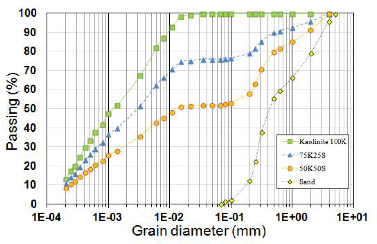
Figure 1
Grain size distribution curves of the tested soils.
Table 1
Geotechnical properties of the tested soils.
| Cc | Cu | <80 μm, | <2 μm, | LL, | PL, | PI, | wSPO, | ρdmax, | |
|---|---|---|---|---|---|---|---|---|---|
| Material | % | % | % | % | % | % | g/cm3 | ||
| Kaolinite 100K (Kheirbek-Saoud 1994) [33] | 0.44 | 11.67 | 100 | 58 | 40 | 20 | 20 | 17.2 | 1.7 |
| Sand | 0.67 | 3,15 | 0 | 0 | - | - | - | - | - |
| 75K25S | 0.25 | 25 | 77 | 43 | 31.7 | 18.5 | 13.2 | 15.8 | 1.77 |
| 50K50S | 0.067 | 913.04 | 53 | 36 | 25.1 | 14.8 | 10.3 | 12 | 1.93 |
[i] Cc: curvature coefficient, Cu: uniformity coefficient, LL: liquid limit, PL: plasticity limit, PI: plasticity index, wSPO: optimum water content in standard Proctor optimum SPO conditions, ρdmax: maximum dry density
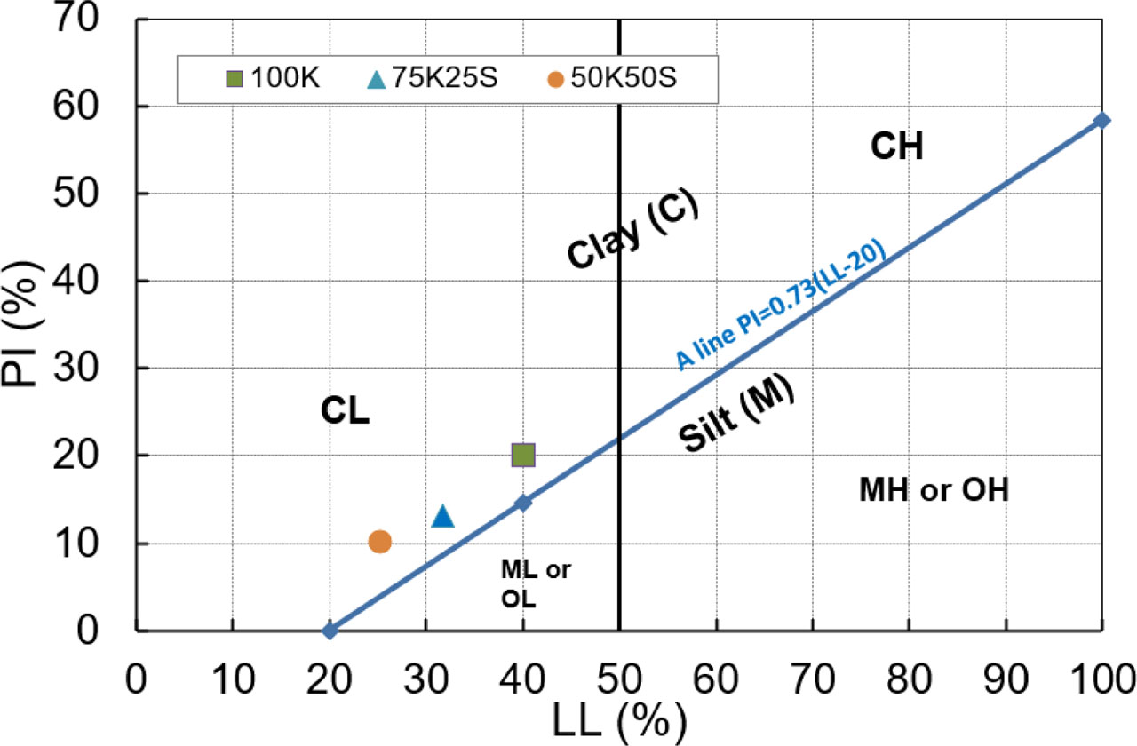
Figure 2
Atterberg limits of the tested soils.
LL: liquid limit, PI: plasticity index
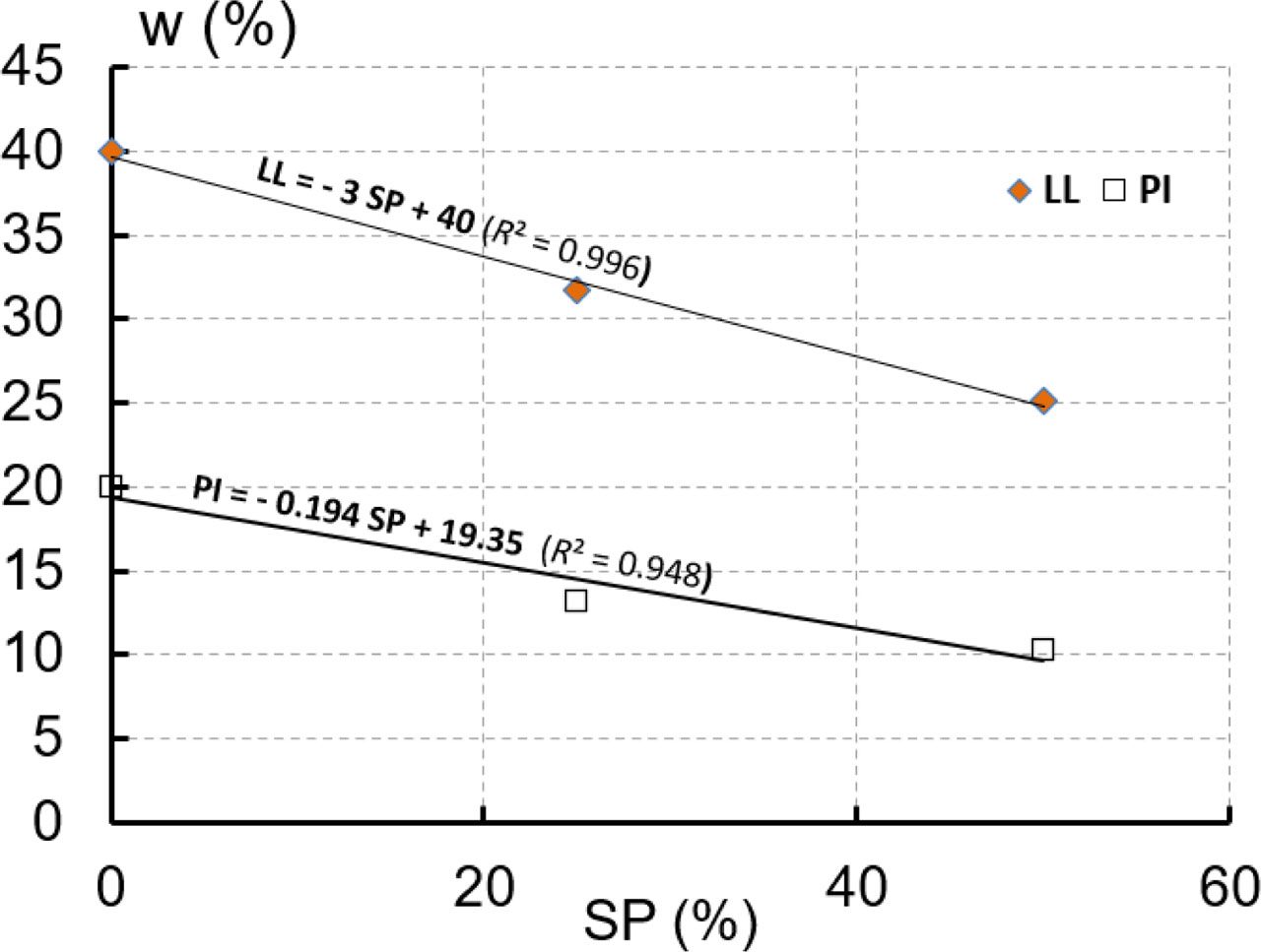
Figure 3
LL and PI versus SP.
LL: liquid limit, PI: plasticity index, SP: sand percentage
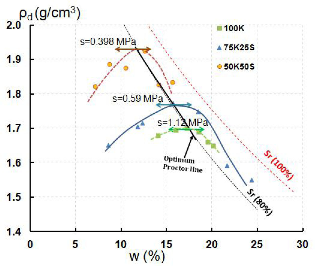
Figure 4
Compaction characteristics for the kaolinite 100K and 75K25S, 50K50S mixtures.
Table 2
Comparison between measured and correlated γdmax and wSPO.
| Soils | LL, | Measured | Correlated | Error | Measured | Correlated | Error |
|---|---|---|---|---|---|---|---|
| % | wSPO, % | wSPO, % | ΔwSPO, % | γdmax, kN/m3 | γdmax, kN/m3 | Δγdmax, kN/m3 | |
| 100K | 40 | 17.2 | 18.5 | 1.3 | 17 | 16.9 | 0.1 |
| 75K25S | 31.7 | 15.8 | 15.4 | 0.4 | 17.7 | 17.7 | 0 |
| 50K50S | 25.1 | 12 | 12.8 | 0.8 | 19.3 | 18.3 | 1.0 |
[i] LL: liquid limit
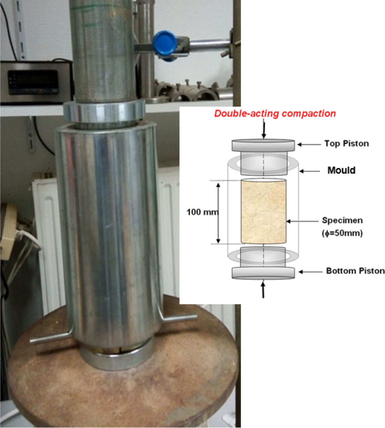
Figure 5
Compacted sample device.
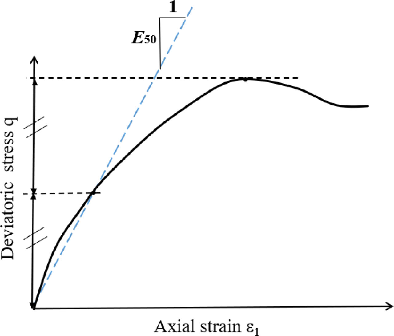
Figure 6
E50 modulus definition.
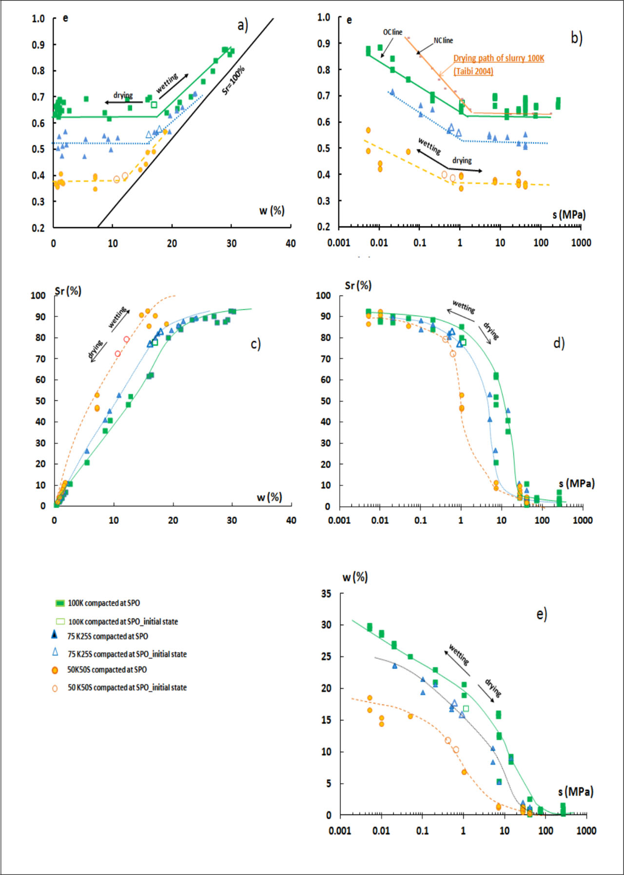
Figure 7
Wetting–drying paths of compacted samples of kaolinite 100K and mixtures 75K25S and 50K50S.
Table 3
Initial conditions of drying–wetting test.
| Material | LL, | wSPO, | ρdmax, | si measured, | si correlated, |
|---|---|---|---|---|---|
| % | % | g/cm3 | MPa | MPa | |
| 100K | 40 | 17.2 | 1.7 | 1.12 | 0.729 |
| 75K25S | 31.7 | 15.8 | 1.77 | 0.59 | 0.644 |
| 50K50S | 25.1 | 12 | 1.93 | 0.398 | 0.339 |
[i] LL: liquid limit
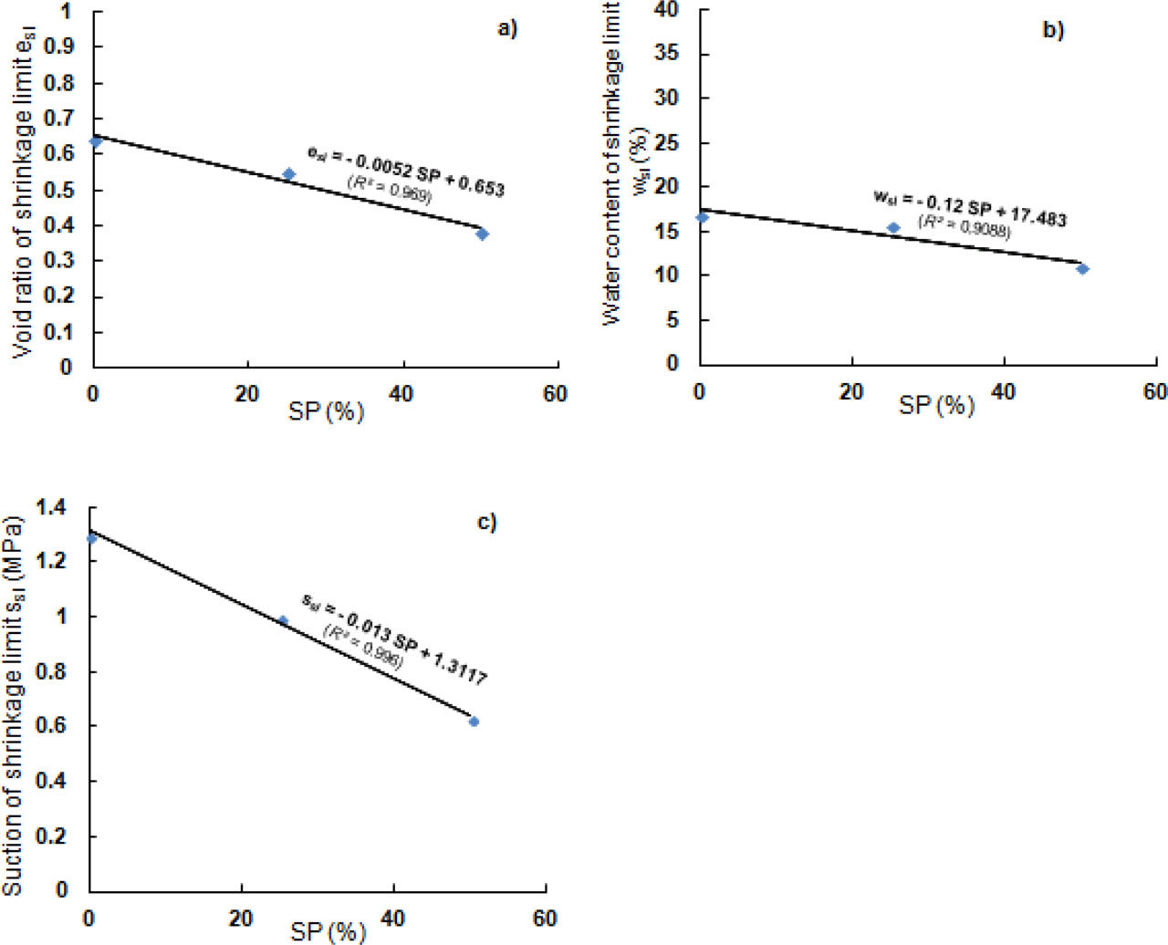
Figure 8
The relationship between: a) void ratio eSl, b) water content wsl and c) suction ssl of shrinkage limit versus SP.
SP: sand percentage
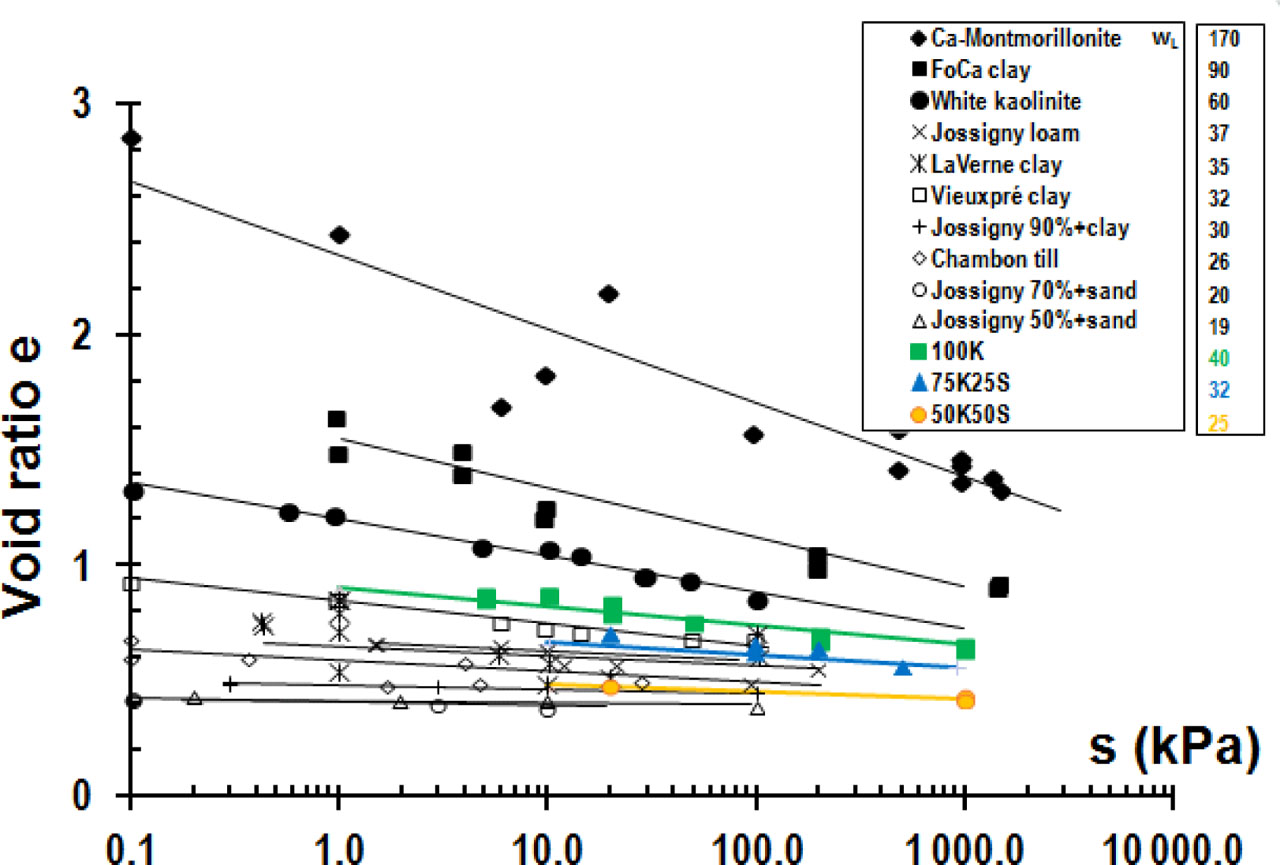
Figure 9
Void ratio for wetting paths of different soils compacted in SPO conditions.
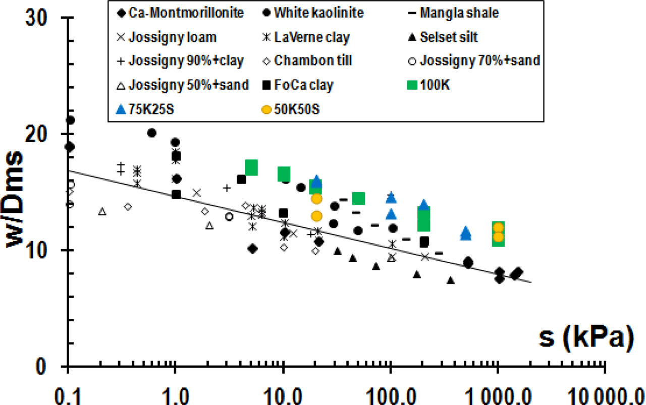
Figure 10
Normalised water contents for the wetting paths of different soils compacted in SPO conditions.
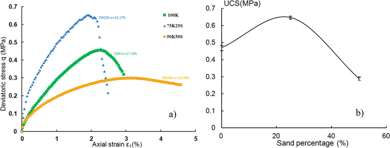
Figure 11
Relationship between a) deviatoric stress and axial strain for kaolinite and mixture samples, b) UCS and sand percentage, in SPO conditions. UCS: unconfined compressive strength.
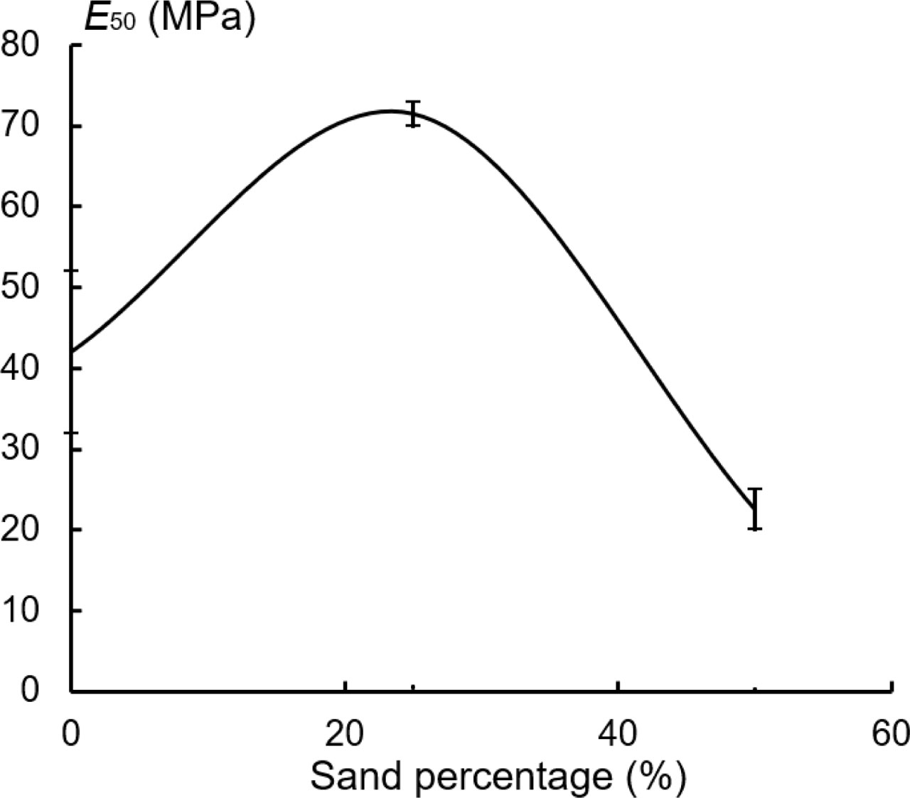
Figure 12
Relationship between E50 modulus and sand percentage for kaolinite and mixture samples in SPO conditions.
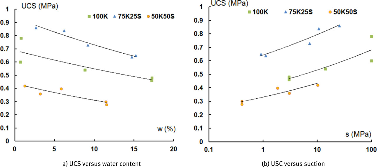
Figure 13
Relationship between UCS and a) water content, b) suction for 100K and mixture samples.. UCS: unconfined compressive strength
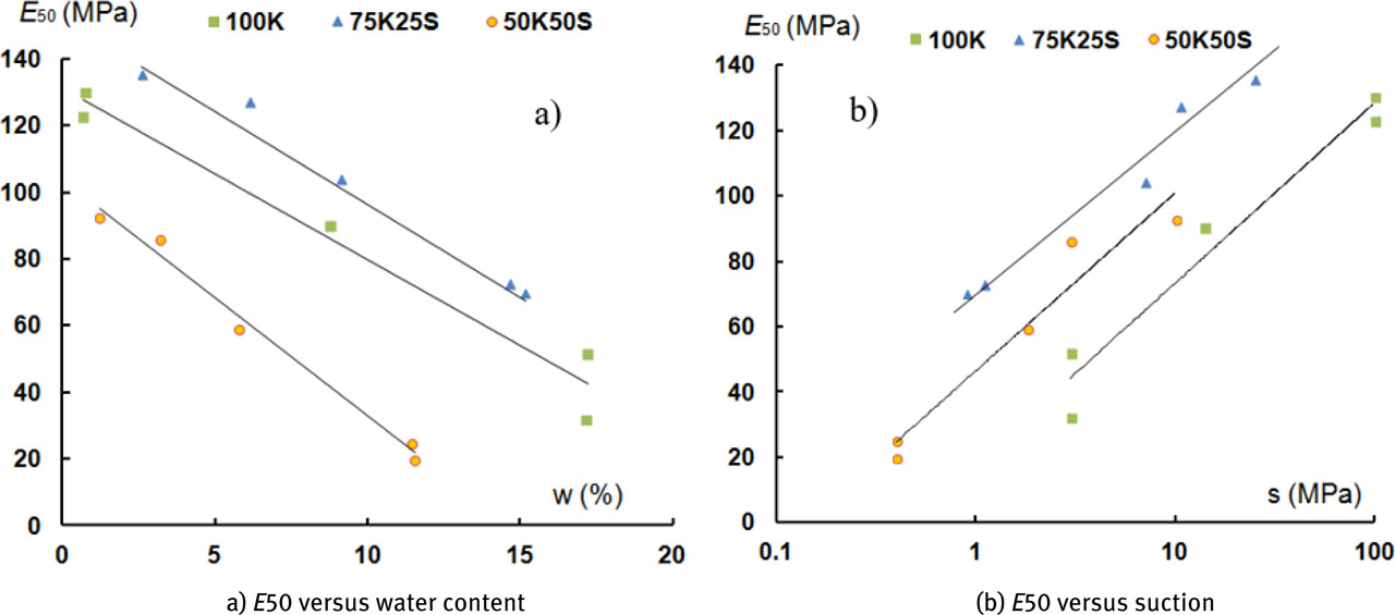
Figure 14
Relationship between E50 modulus and a) water content and b) suction for 100K and mixture samples.
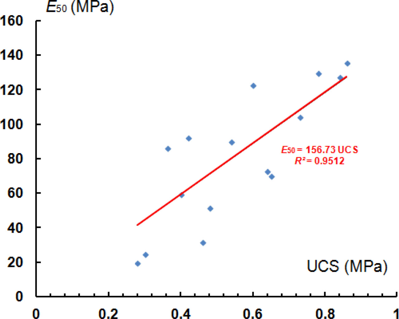
Figure 15
Relationship between E50 modulus and UCS. UCS: unconfined compressive strength.