
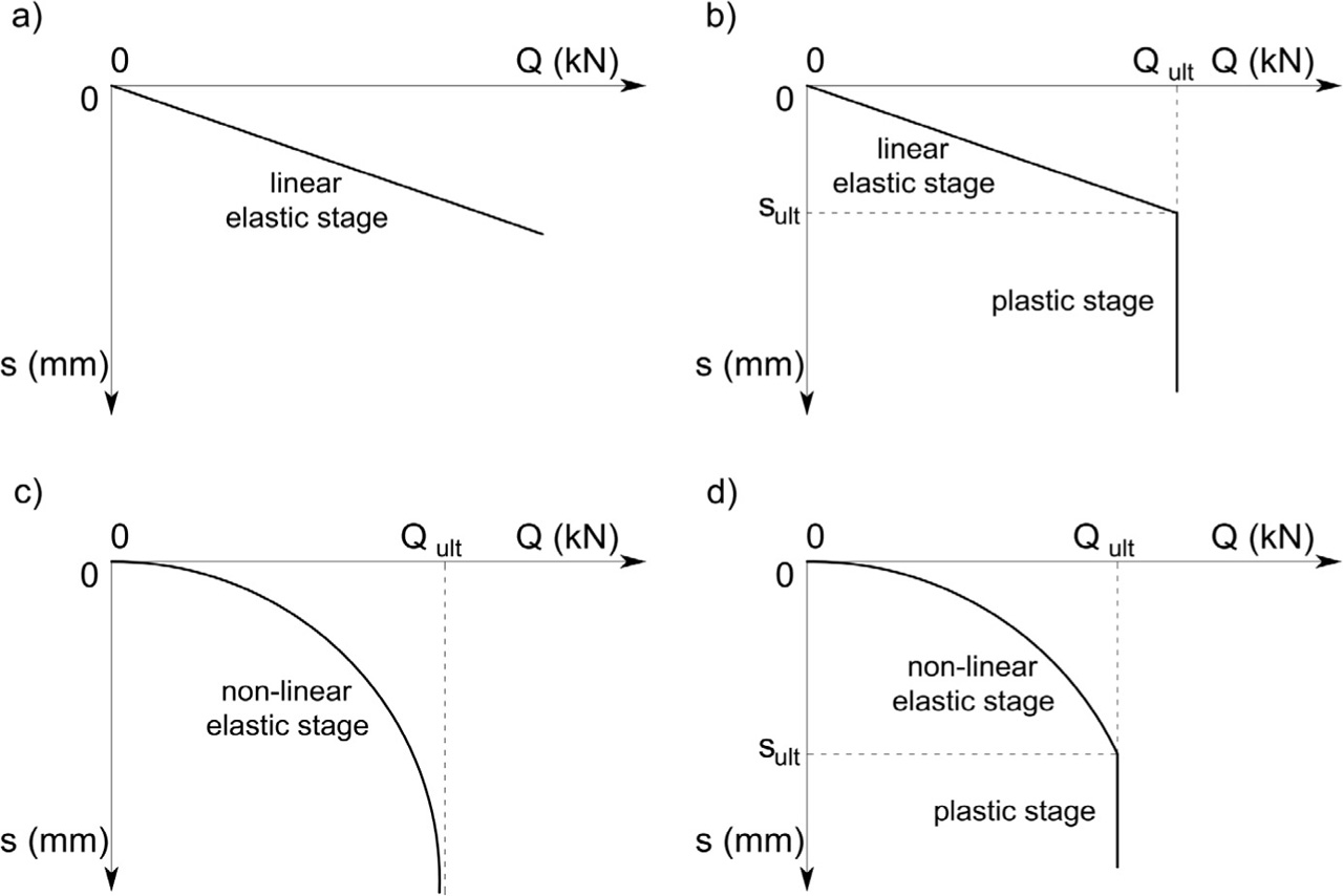
Figure 1
Theoretical model of pile and soil interaction: a) perfectly elastic; b) linear elastic and plastic; c) non-linear elastic; d) non-linear elastic with plastic yielding.
Table 1
Compilation of data used for correlation analysis.
| Location | Number of piles | Geometry of piles | Number of CPTs | Distance between pile and CPT | Soil under pile base | ||
|---|---|---|---|---|---|---|---|
| D | Db* | L | |||||
| (mm) | (mm) | (m) | (m) | ||||
| Gdańsk | 5 | 406 | 460 | 9.0 to 13.5 | 6 | 2.0 to 10.0 | FSa |
| 9 | 508 | 560 | 16.0 to 22.0 | 7 | 2.0 to 10.0 | FSa | |
| Gdynia | 14 | 560 | 610 | 14.0 to 18.0 | 10 | 2.0 to 6.0 | FSa |
| Grudziądz | 16 | 508 | 560 | 10.6 to 20.0 | 12 | 1.0 to 8.0 | FSa, MSa |
| Hajnówek | 4 | 508 | 560 | 7,5 | 4 | 4.0 to 6.0 | CSa, FSa |
| Olsztynek | 44 | 610 | 660 | 6.5 to 12.0 | 30 | 1.0 to 6.0 | MSa |
| Szczecin | 13 | 408 | 460 | 12.0 to 14.0 | 6 | 2.0 to 10.0 | MSa, FSa |
| 6 | 457 | 510 | 17.6 to 18.4 | 6 | 1.0 to 8.0 | FSa | |
| 10 | 457 | 520 | 17.5 to 21.5 | 9 | 1.0 to 6.0 | FSa | |
| Wrocław | 4 | 610 | 660 | 8.5 to 11.0 | 4 | 2.0 to 6.0 | CSa, MSa |
| 12 | 508 | 560 | 6.0 to 18.0 | 8 | 2.0 to 6.0 | CSa, MSa | |
| S | 137 | 102 | |||||
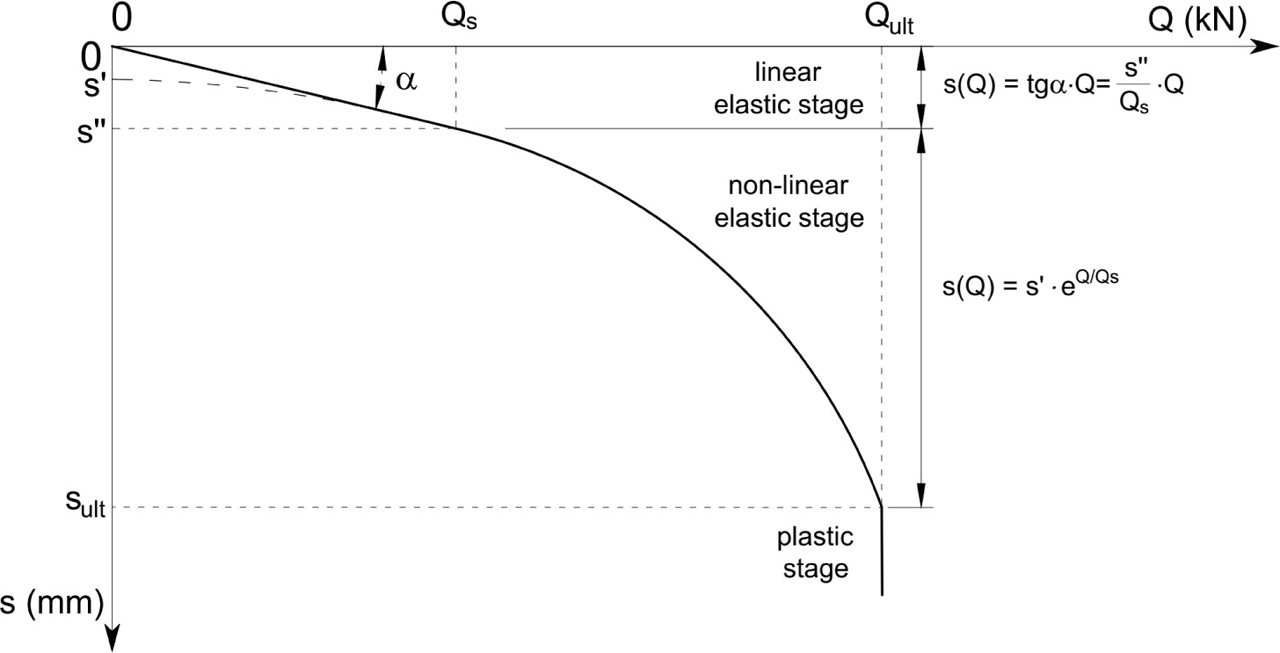
Figure 2
Theoretical model of load–settlement curve.
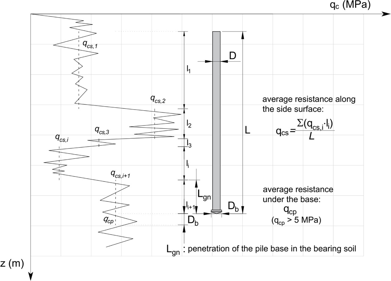
Figure 3
Template of averaging resistance from CPT probing.
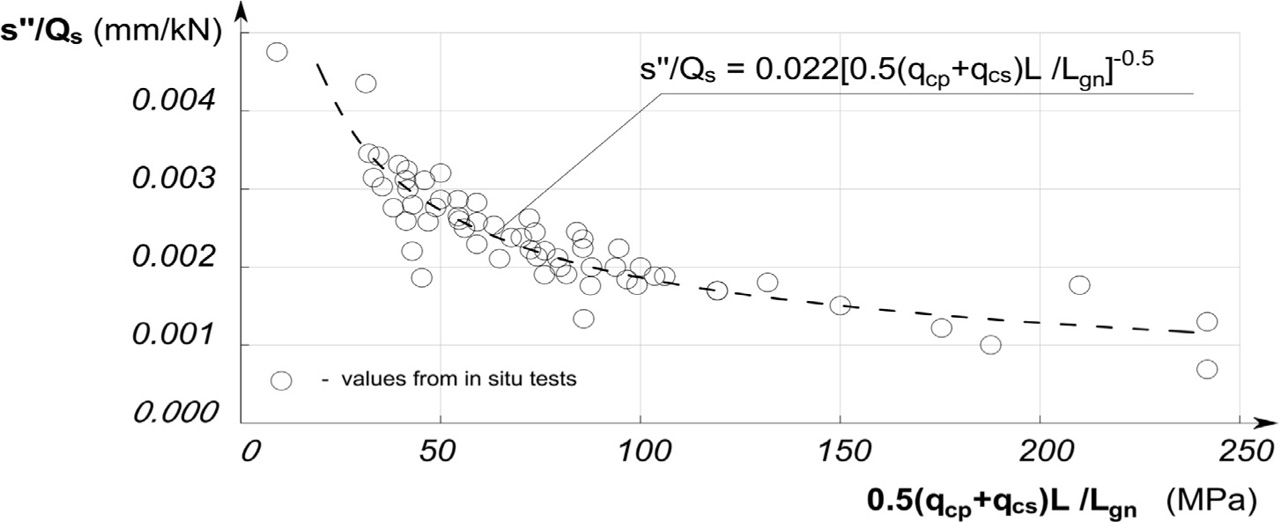
Figure 4
Dependence of ground susceptibility on parameters of the soil and pile geometry.
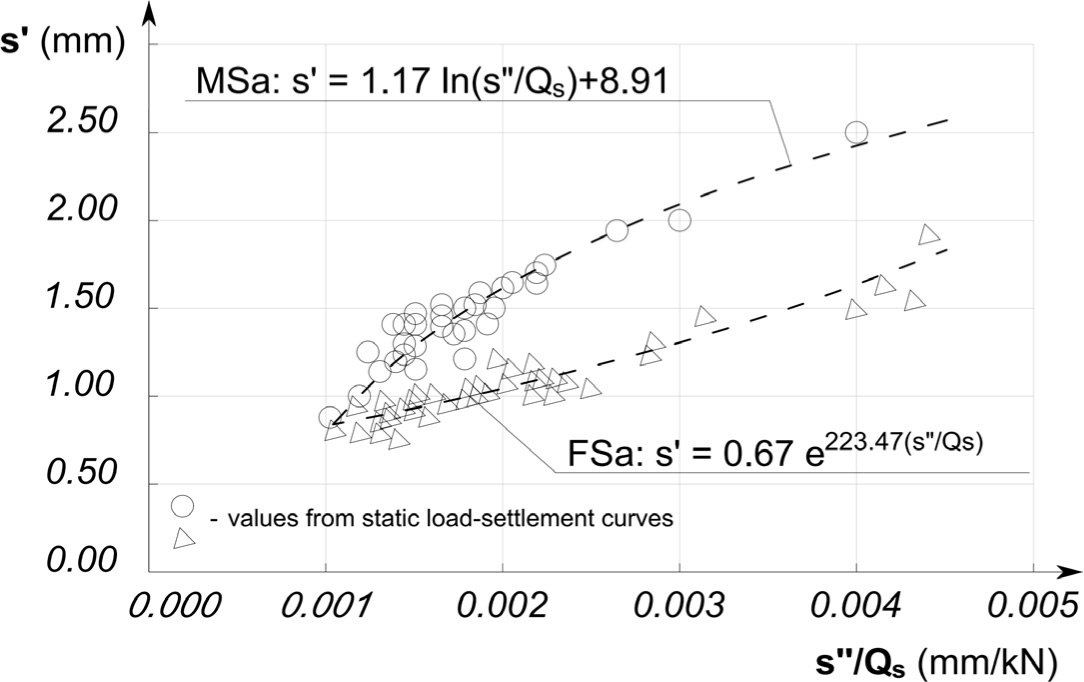
Figure 5
Dependence of the initial point of the exponential function s’ on ground susceptibility.
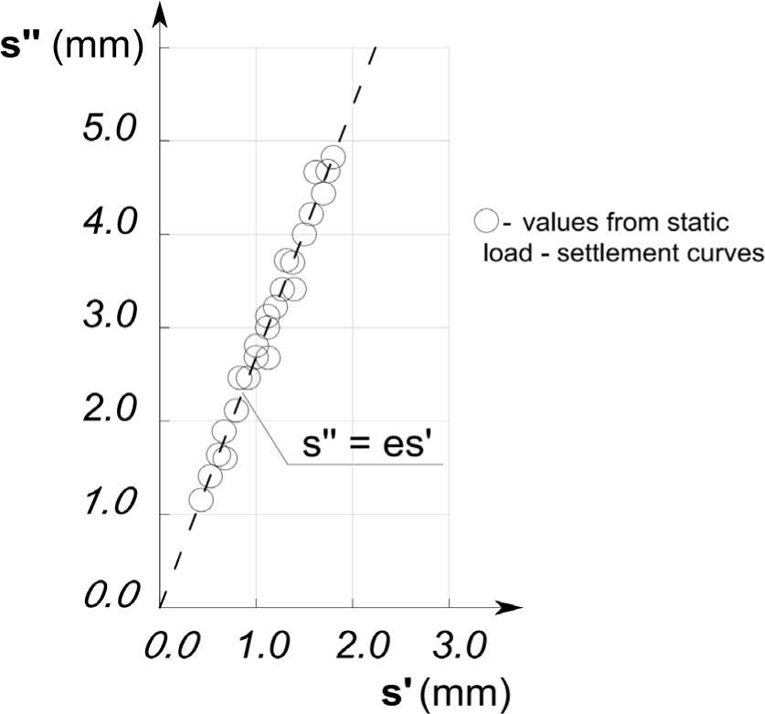
Figure 6
Relationship between the directional coefficients of the linear function s’’ and the non-linear function s’.
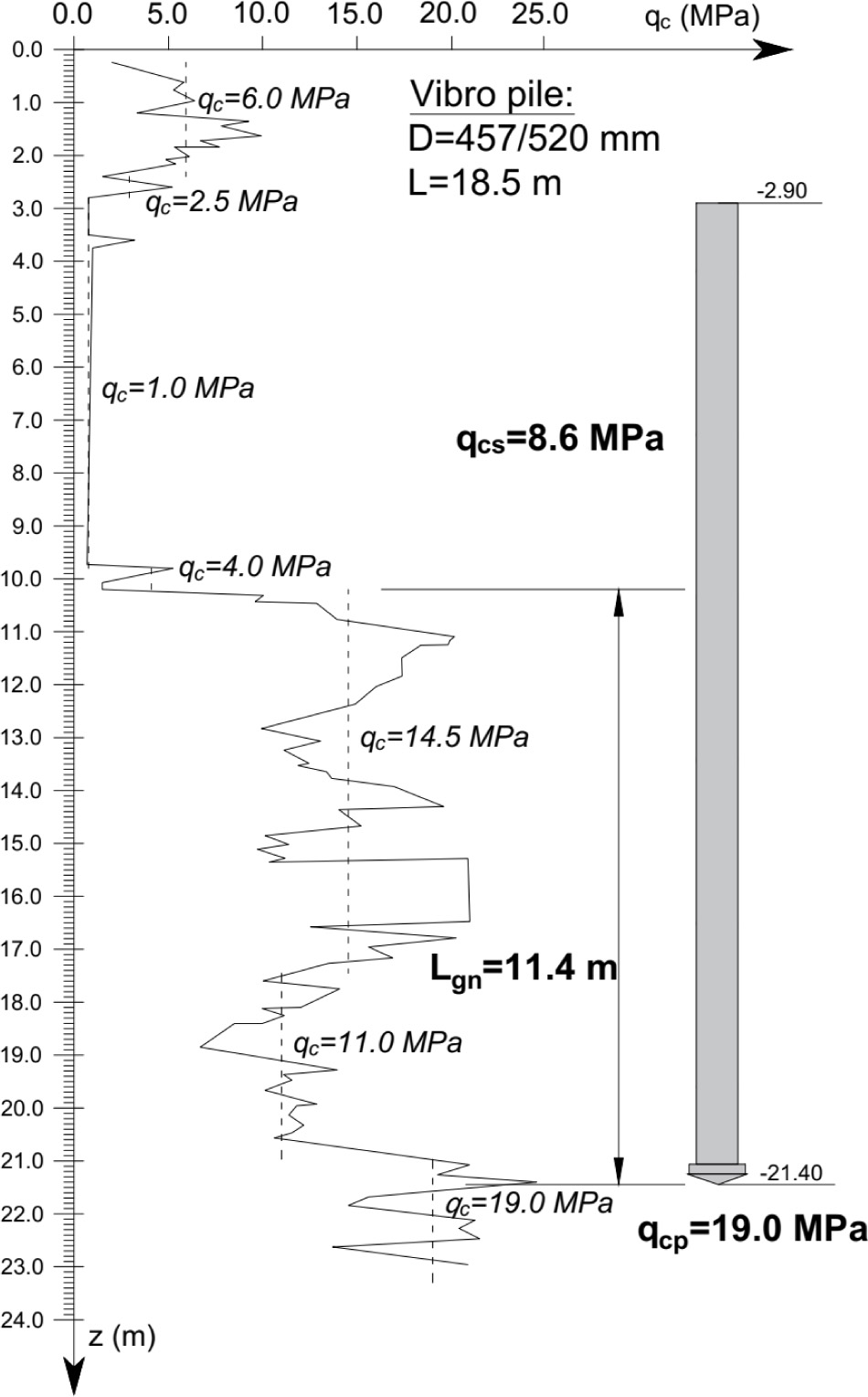
Figure 7
Results of probing and averaged parameters from CPT testing.
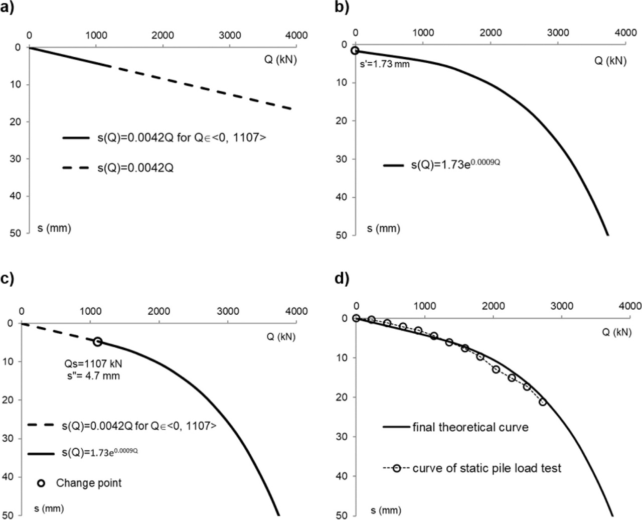
Figure 8
Stages of Q–s characteristics prediction based on the proposed procedure: (a) linear elastic stage; (b) non-linear elastic stage; (c) combination of the linear elastic stage for Q□<0, Qs> and non-linear elastic stage; (d) comparison of the theoretical curve with the measured curve from static load test.
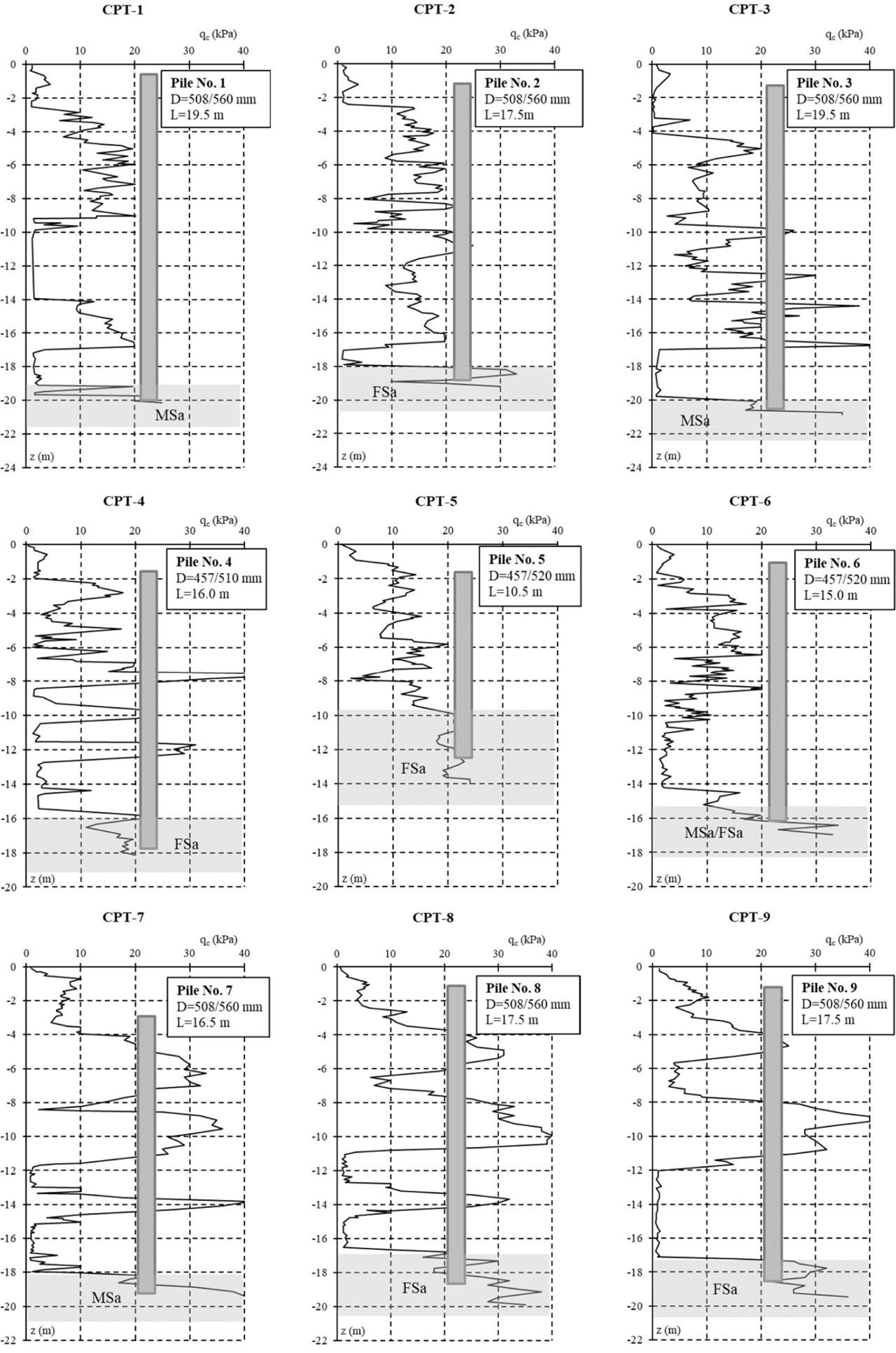
Figure 9
Diagrams of resistance qc for example piles (Gdańsk: CPT-1 to CPT-3, Szczecin: CPT-4 to CPT-6, Grudziądz: CPT-7 to CPT-9).
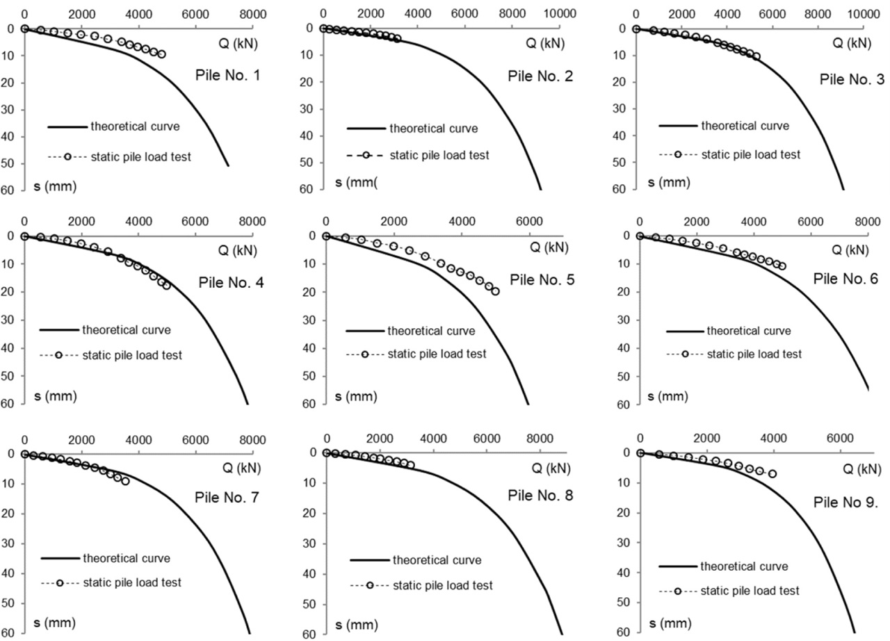
Figure 10
Comparison of theoretical curves with actual curves from static pile load tests.
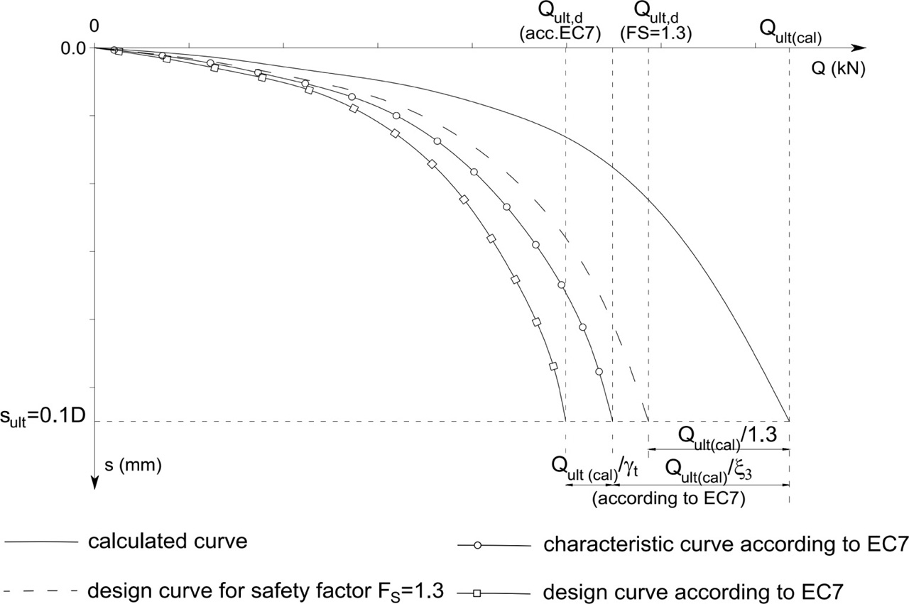
Figure 11
Concept for generation of safe design curve.
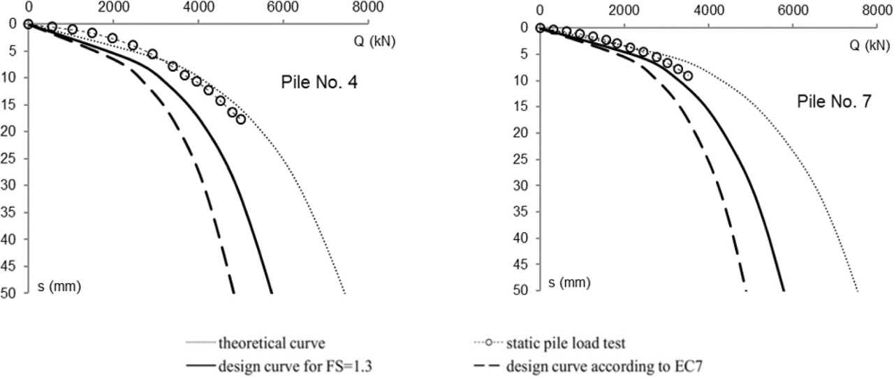
Figure 12
Comparison of design curves and curves from SPLT.
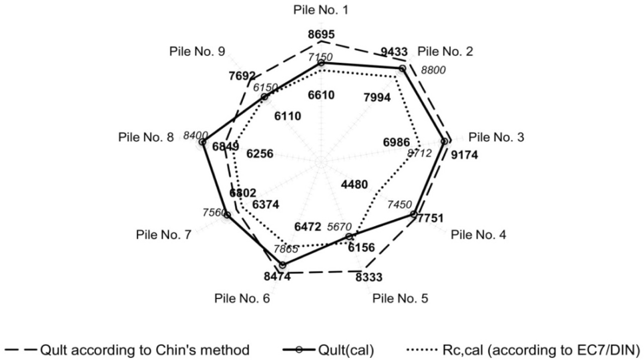
Figure 13
Values of calculated limit of load-bearing capacity.
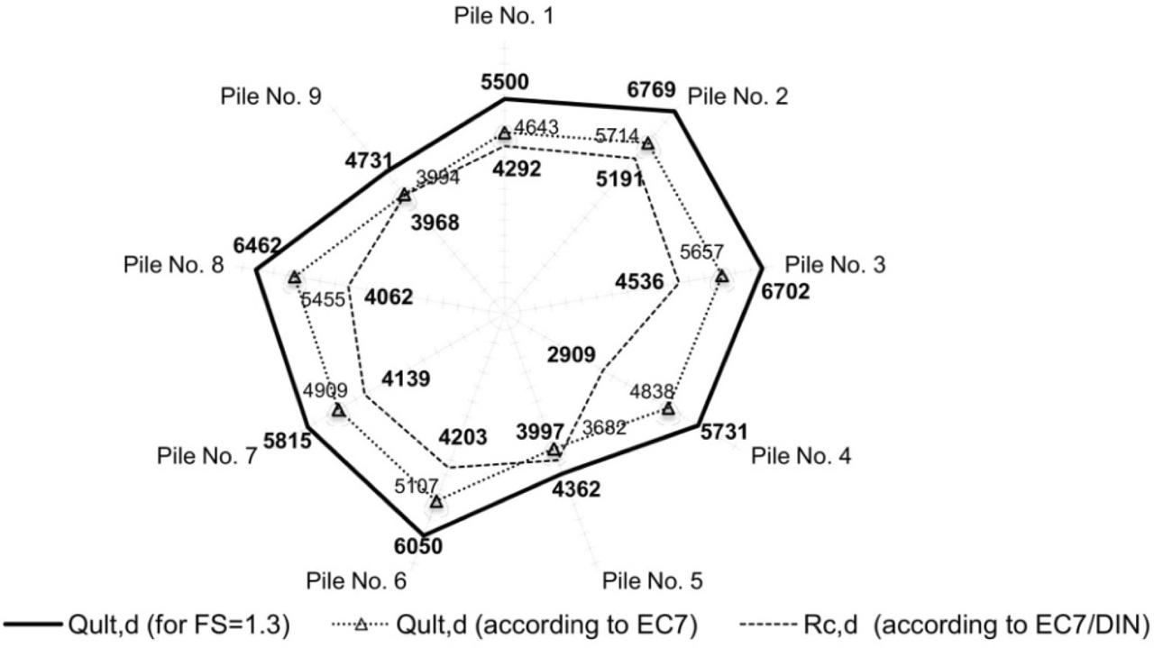
Figure 14
Comparison of design load-bearing capacity from diverse design methods.
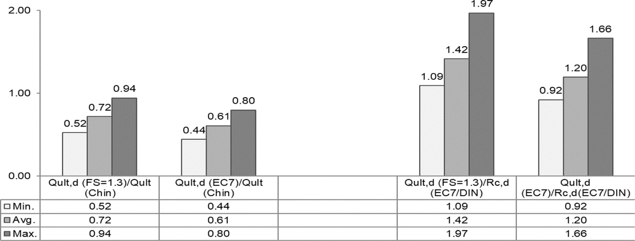
Figure 15
Summary of ultimate bearing capacity values from diverse design methods.