
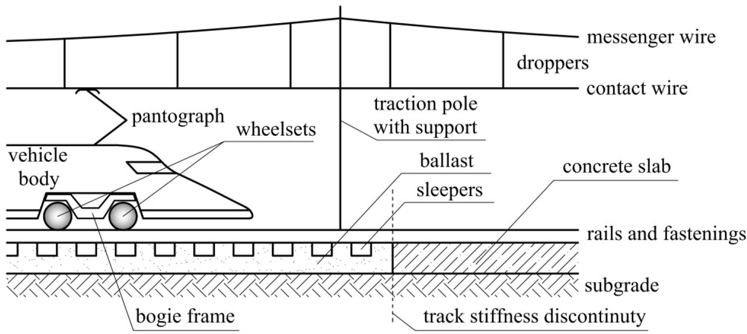
Figure 1
Scheme of catenary–train–track system with distinctive particular elements.
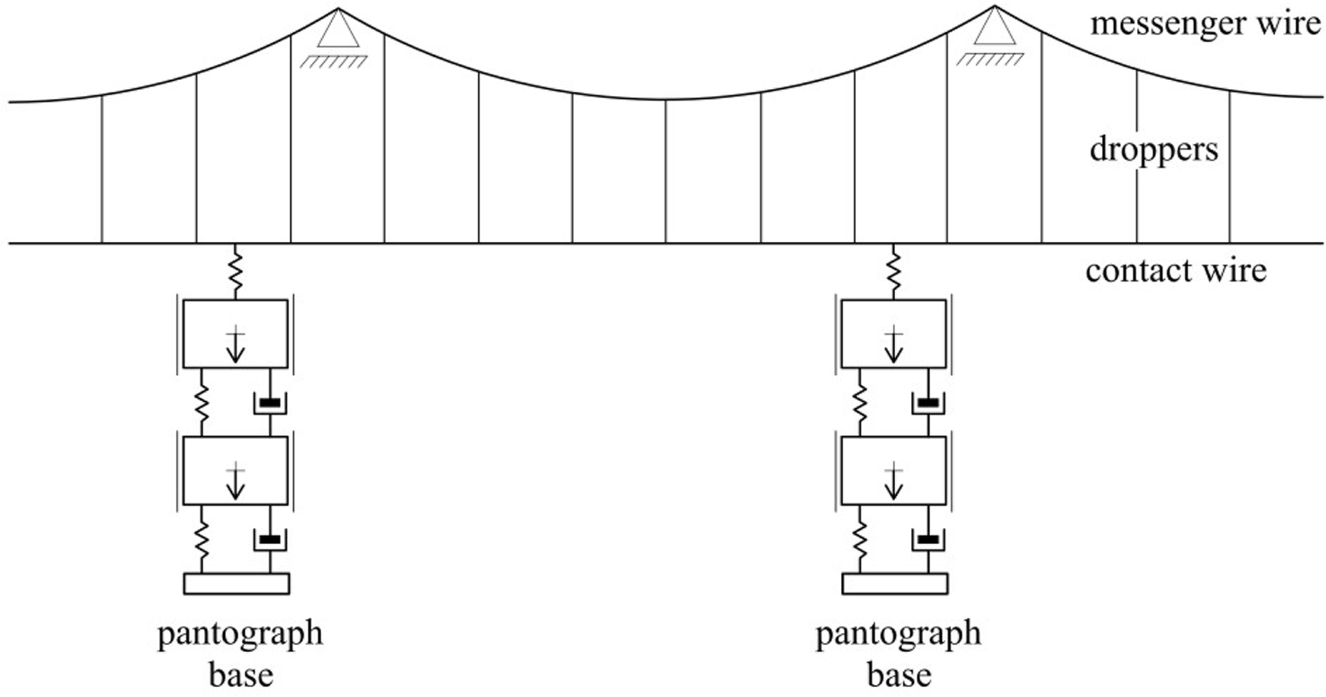
Figure 2
Dynamic model of the catenary-pantographs subsystem.
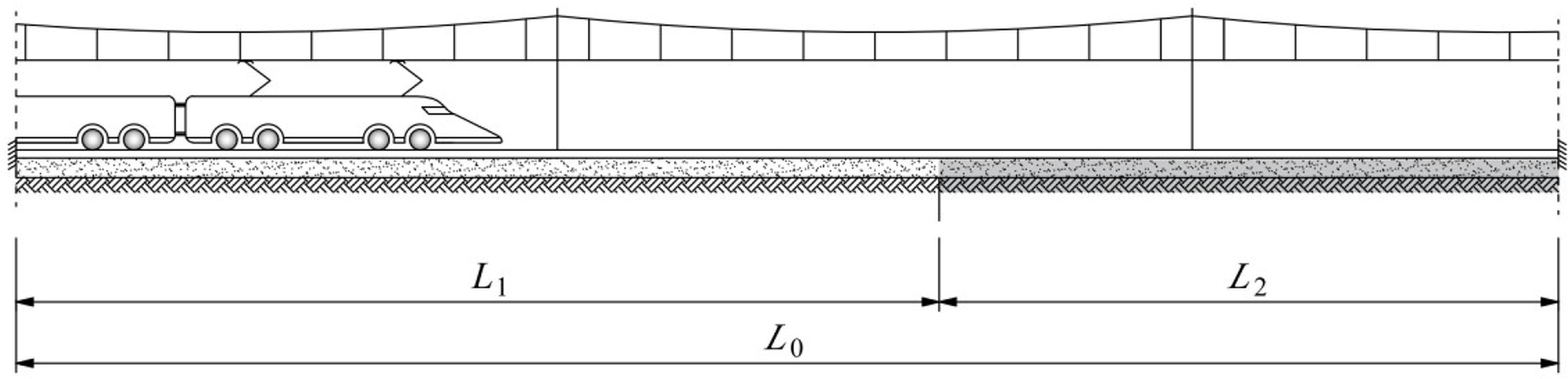
Figure 3
Schematic diagram of the track test section.
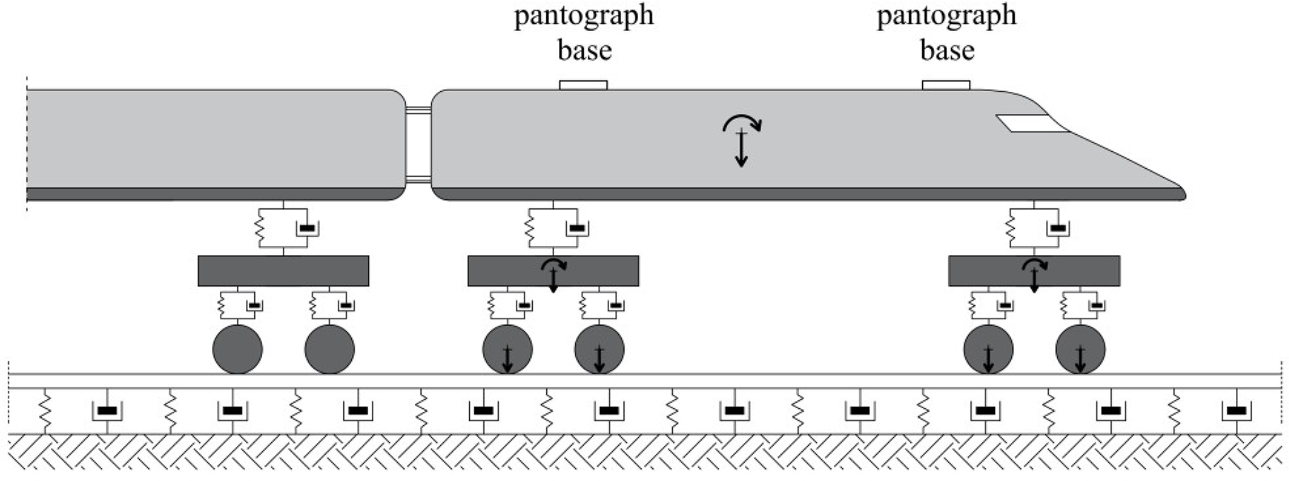
Figure 4
Dynamic model of the train-track subsystem with marking vehicle degrees of freedom.
Table 1
Vehicle parameters (from Bryja et al. [23]).
| Mass of fully loaded vehicle body | 3.60×10⁴ kg | Stiffness of primary suspension (single spring) | 2.540×10⁶ N/m |
| Central rotational moment of the vehicle body mass | 1.894×10⁶ kgm2 | Damping of primary suspension (single damper) | 1.963×10⁴ Ns/m |
| Mass of the bogie | 4.95×10³ kg | Stiffness of secondary suspension (single spring) | 8.870×10⁵ N/m |
| Central rotational moment of the bogie mass | 6.150×10³ kgm2 | Damping of secondary suspension (single damper) | 4.335×10⁴ Ns/m |
| Mass of the wheelset | 2.40×10³ kg | Arrangement of a train | |
 | |||
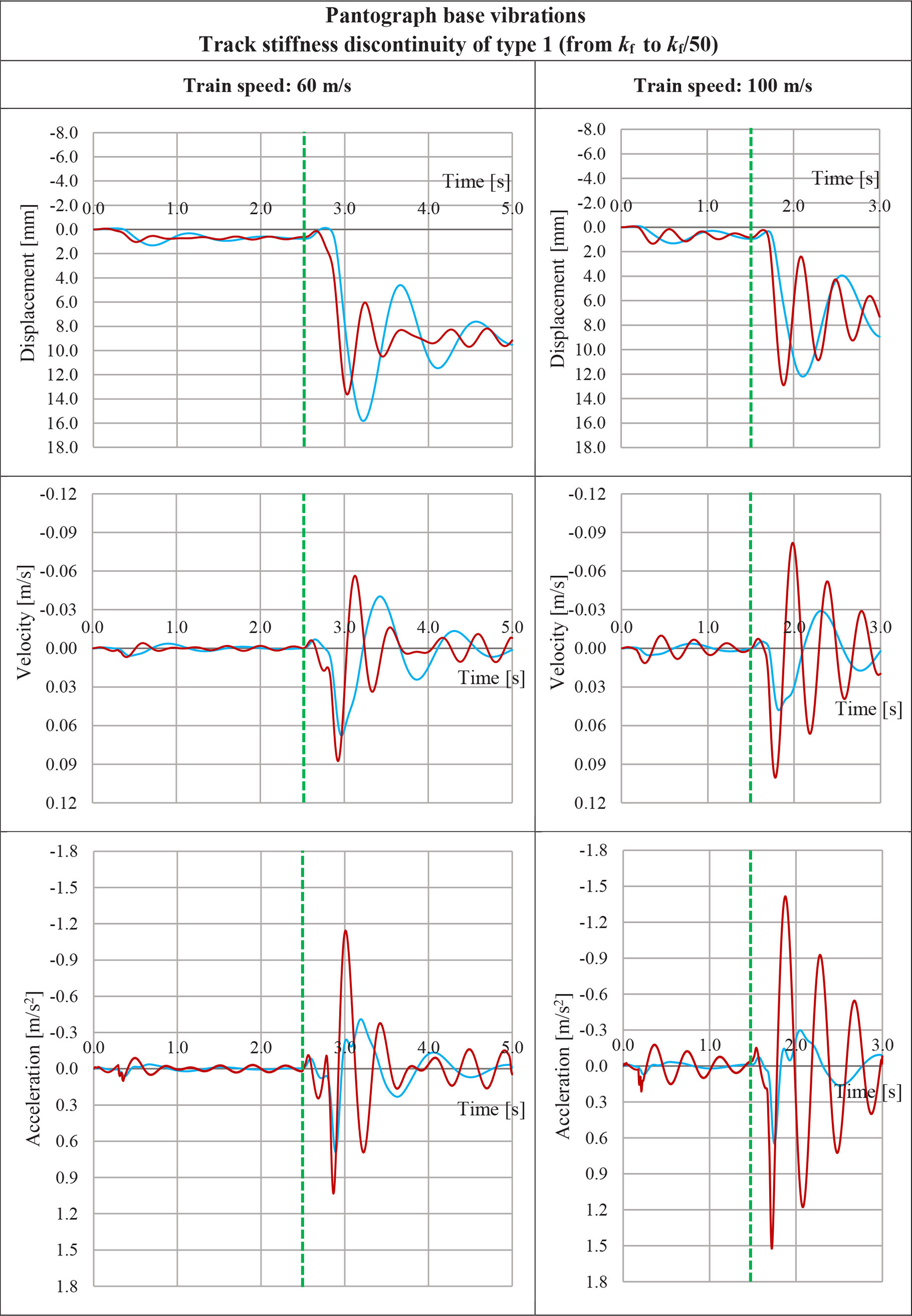
Figure 5
Displacements, velocities and accelerations of the pantograph base, during a passage through the track stiffness discontinuity, depending on the vehicle suspension: blue color line indicates vehicle with two-stage suspension and red color line indicates vehicle without secondary suspension.
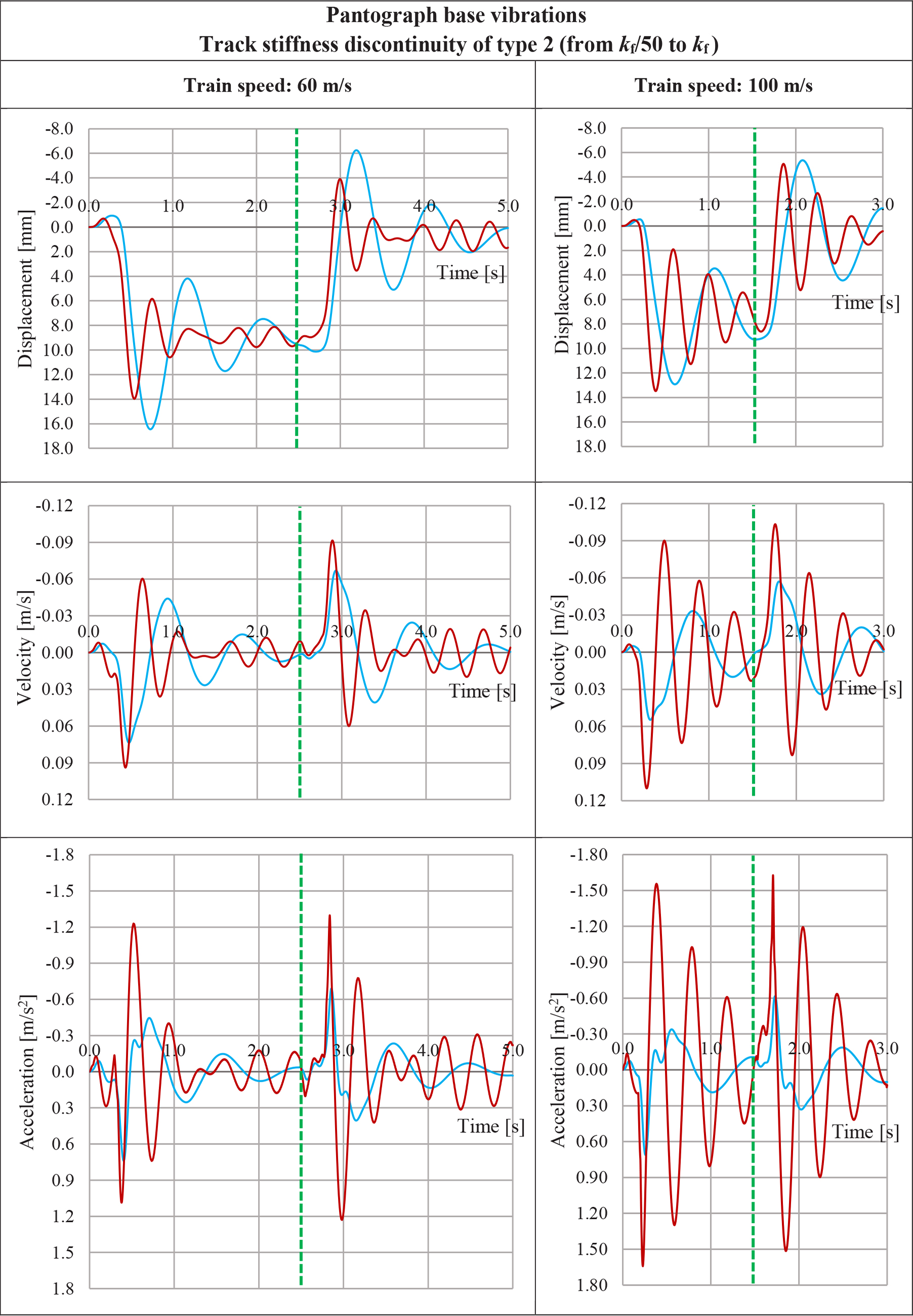
Figure 6
Displacements, velocities and accelerations of the pantograph base, during a passage through the track stiffness discontinuity, depending on the suspension parameters of the vehicle: blue color line indicates vehicle with two-stage suspension and red color line indicates vehicle without secondary suspension.
Table 2
Catenary and pantograph parameters.
| Messenger wire specific mass | 1.07 kg/m | Mass of the pantograph collector head | 7.2 kg |
| Messenger wire tension | 16 kN | Mass of the pantograph articulated frame | 15.0 kg |
| Messenger wire axial stiffness | 12 MN | Pantograph static force | 120 N |
| Contact wire specific mass | 1.35 kg/m | Stiffness of the upper spring of the pantograph | 4200 N/m |
| Contact wire tension | 20 kN | Stiffness of the lower spring of the pantograph | 50 N/m |
| Dropper tensile stiffness | 100 kN/m | Parameter of the upper damper of the pantograph | 10 Ns/m |
| Single span length | 60 m | Parameter of the lower damper of the pantograph | 90 Ns/m |
| Number of droppers within span | 9 | Stiffness of the contact spring | 50 kN/m |
| Material damping coefficient of the messenger wire | 0.5% | Material damping coefficient of the contact wire | 0.5% |
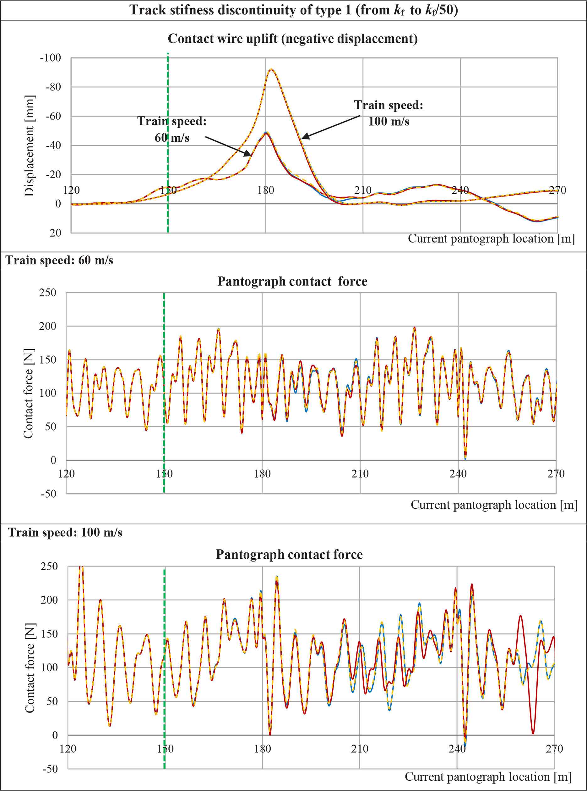
Figure 7
Contact wire uplift at the right steady arm of the middle catenary span and the pantograph contact force, computed under the following conditions: yellow color line indicates a case when vehicle vibrations are not taken into account, blue color line indicates vehicle with two-stage suspension, and red color line indicates vehicle without secondary suspension.
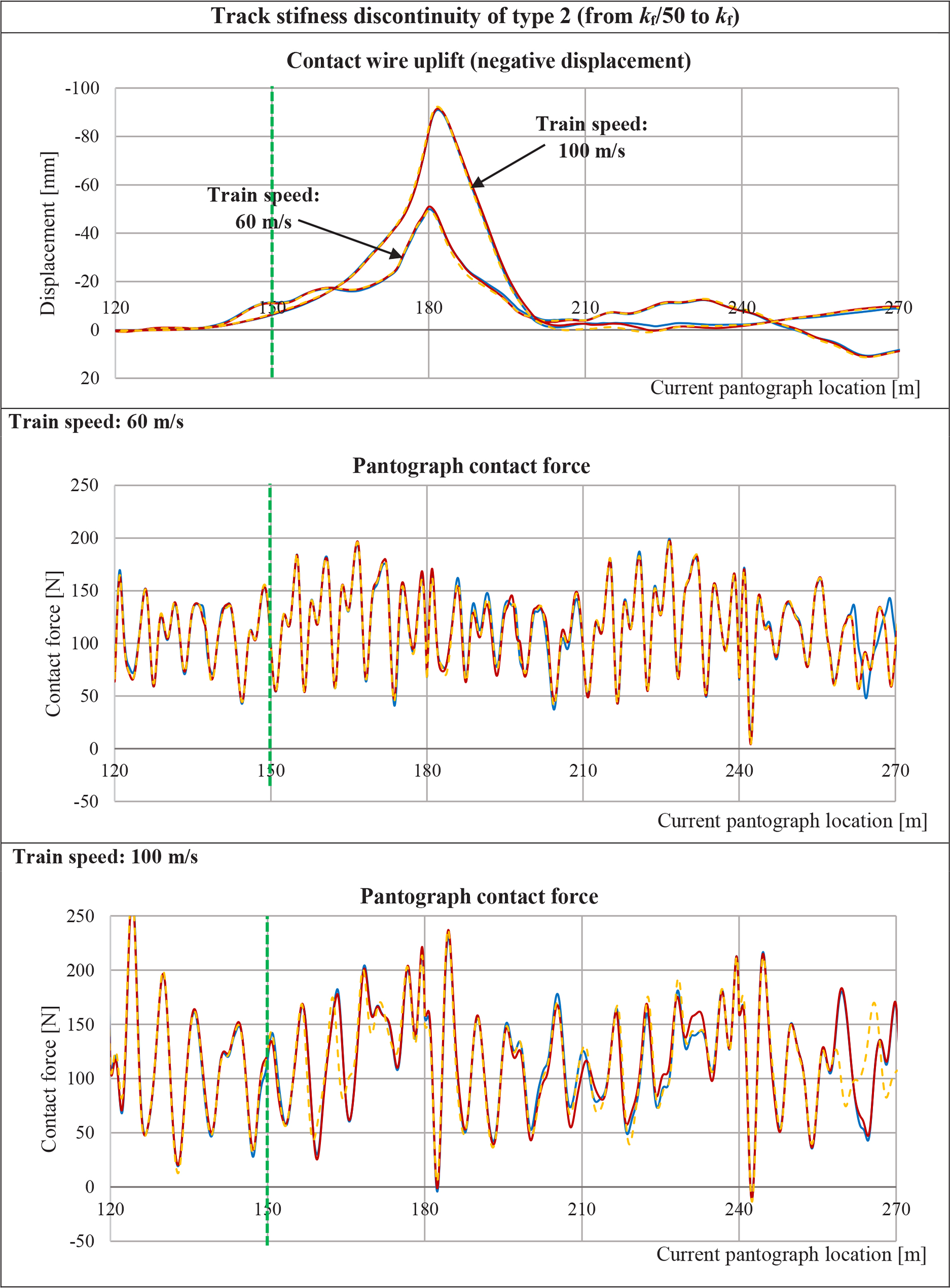
Figure 8
Contact wire uplift at the right steady arm of the middle catenary span and the pantograph contact force, computed under the following conditions: yellow color line indicates a case when vehicle vibrations are not taken into account, blue color line indicates vehicle with two-stage suspension, and red color line indicates vehicle without secondary suspension.