
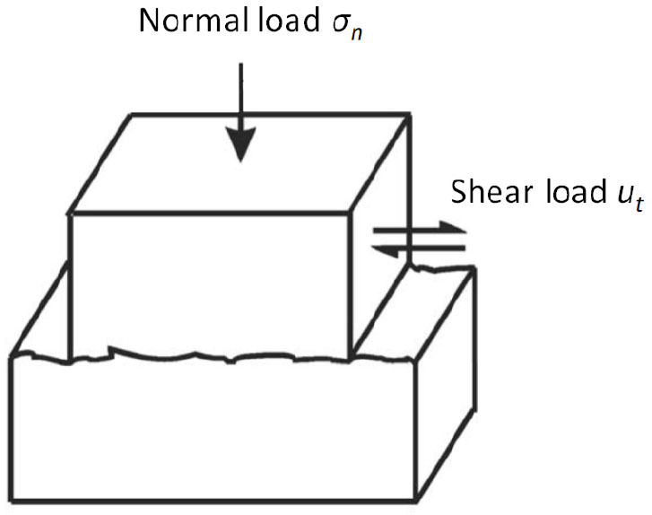
Figure 1
Shear test of rock joint interface[12]
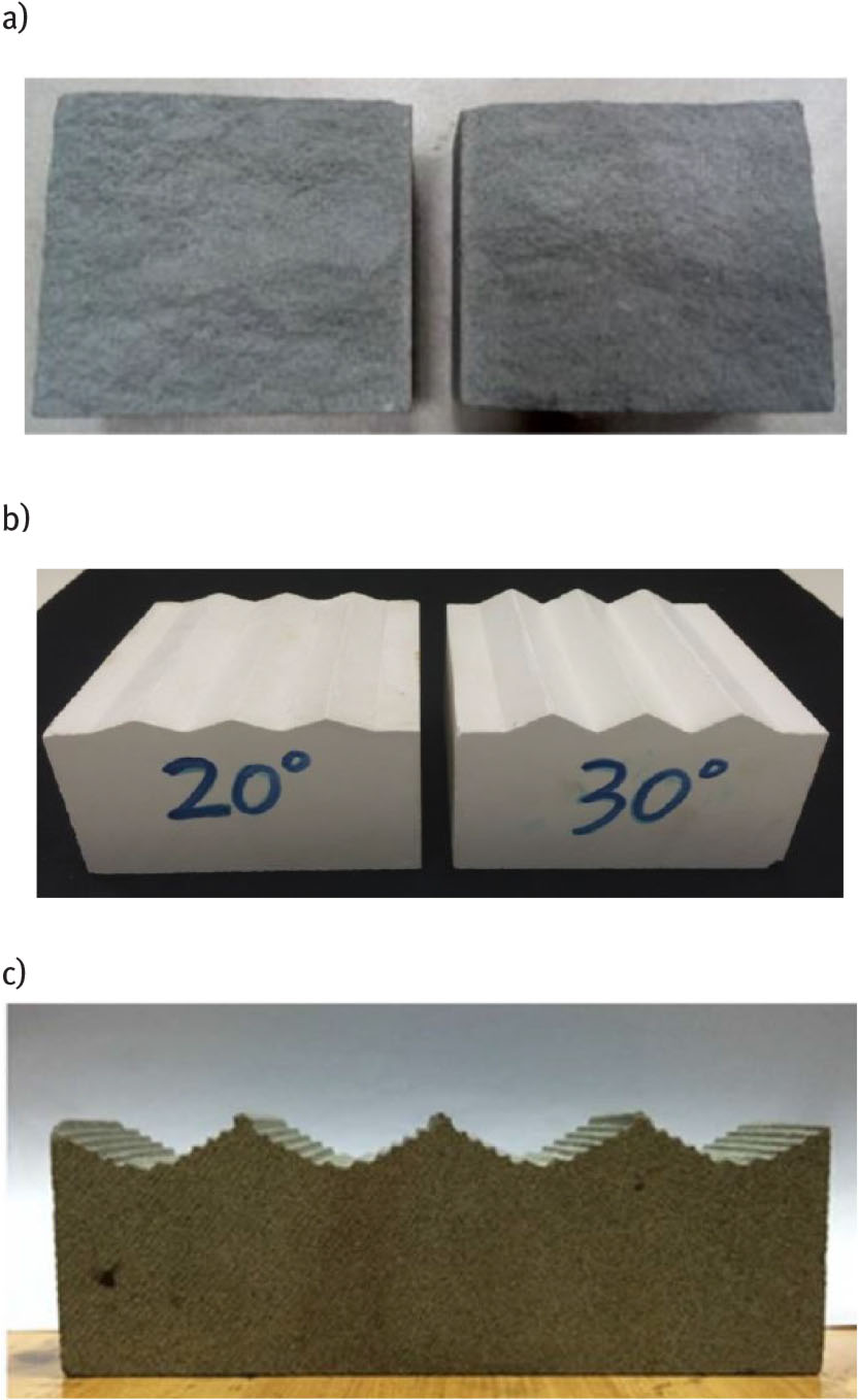
Figure 2
Types of rock joints: a) natural joint,[15] b,c) artificial rock interfaces[13,16]
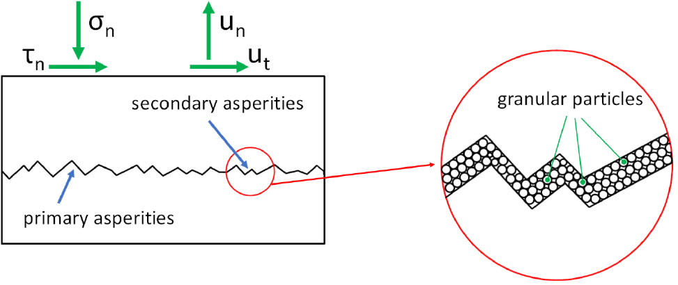
Figure 3
Primary and secondary asperities
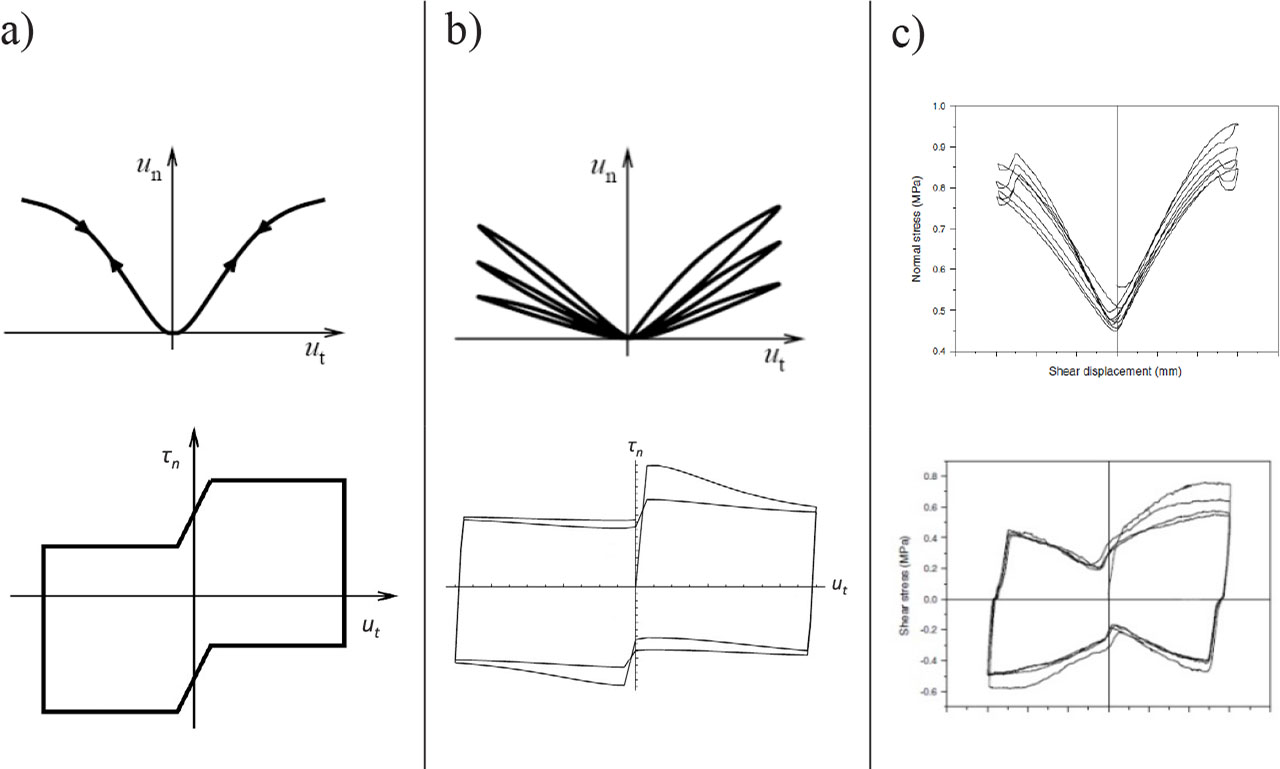
Figure 4
Dilation and stress in cyclic shear test: a) cyclic reversible dilatancy, b) cyclic dilatancy degradation, c) experimental data[22]
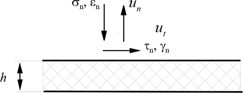
Figure 5
Scheme of the load of joint interface
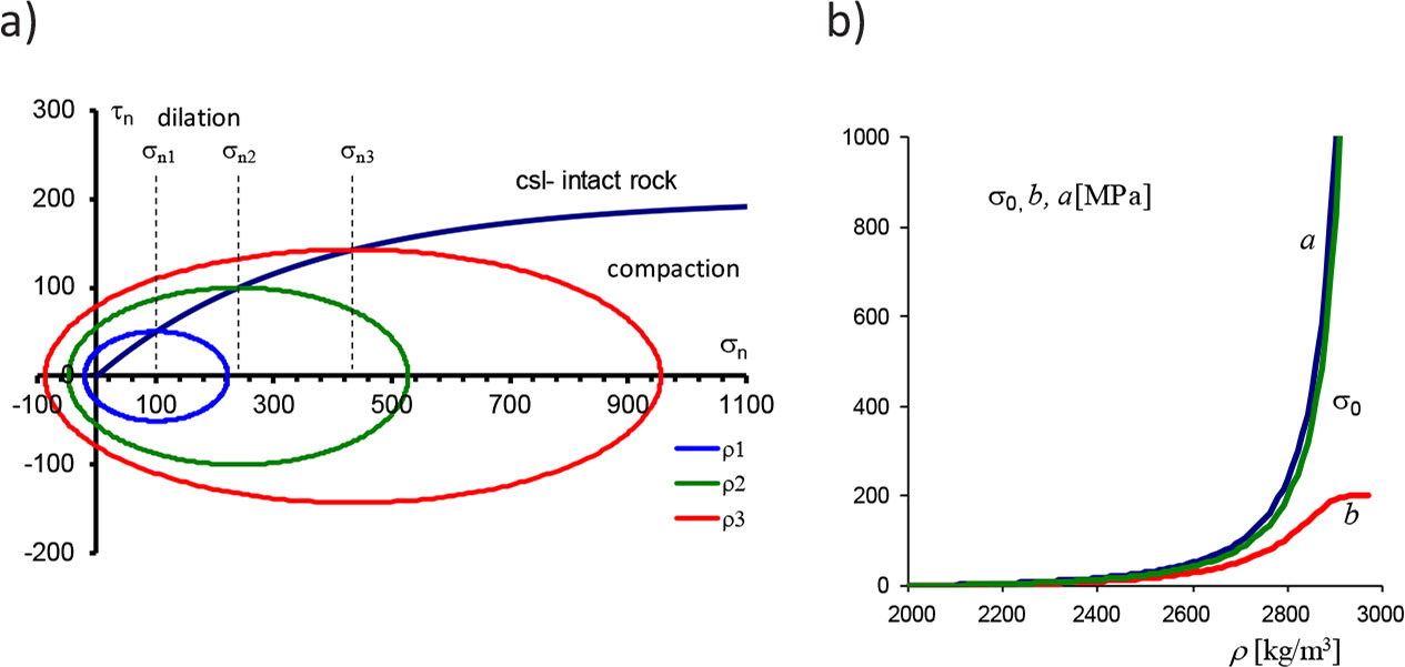
Figure 6
a) Elliptical failure surfaces and critical state line (csl) on plane σn, τn, b) change of ellipse center σ0 and semi-major and semi-minor axes size (a, b) as the function of density ρ
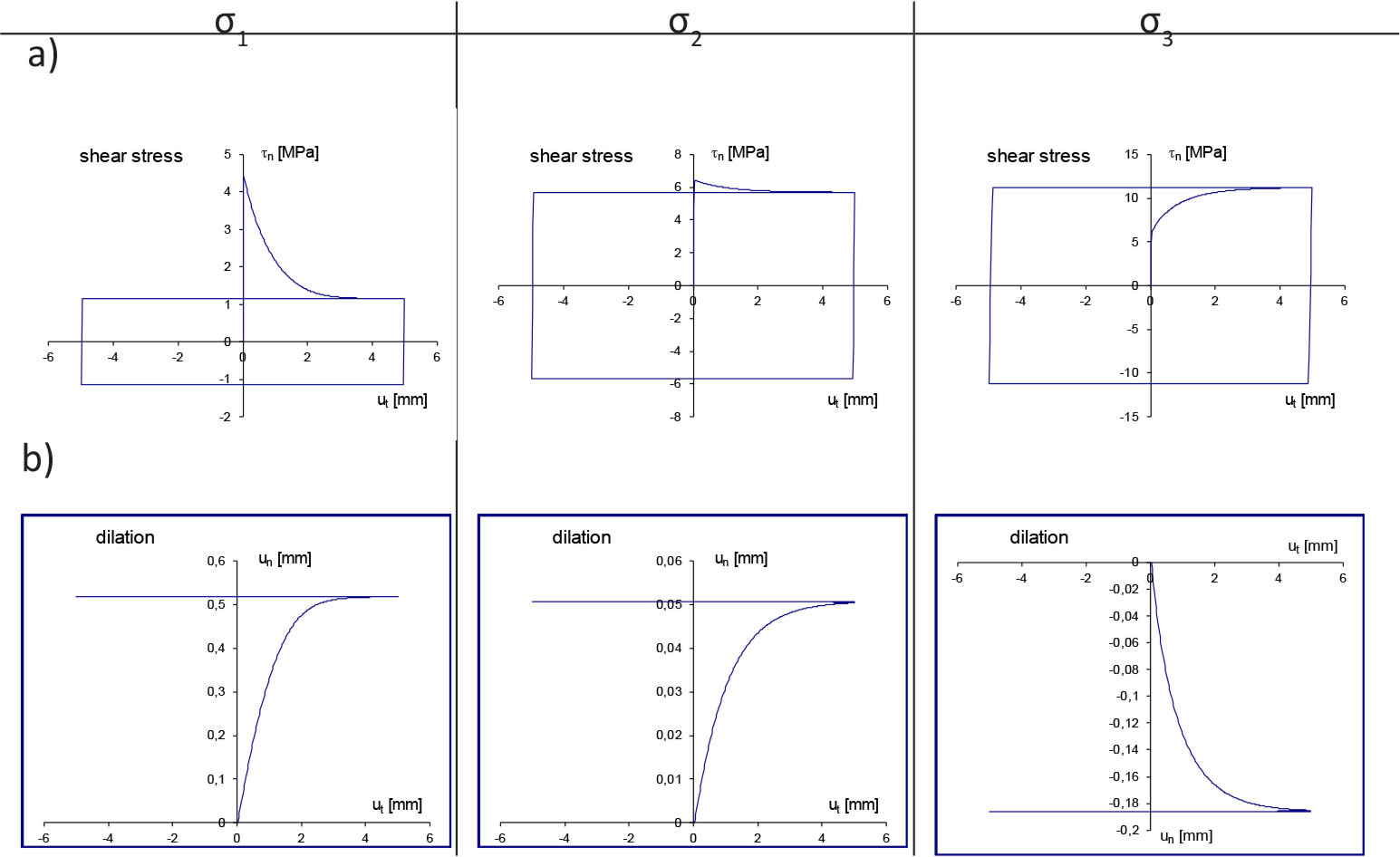
Figure 7
Simulation results for different normal loads (σ1 < σ2 < σ3) depending on the tangential displacement ut: a) variations of shear stress, b) variations of dilatancy

Figure 8
Configurational rearrangement of particles after the change of sliding direction
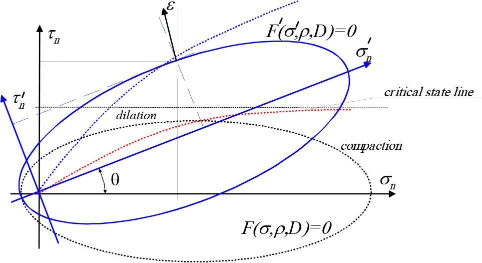
Figure 9
Change of the failure surface position by rotation through an angle θ
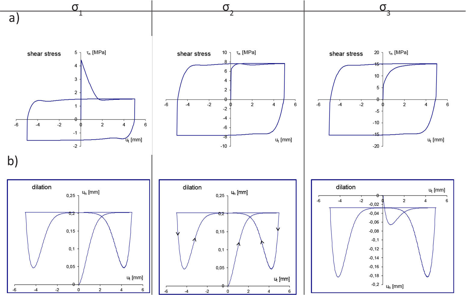
Figure 10
Simulation results for different normal loads (σ1 < σ2 < σ3, ρini = 2.3·103kg/m3, θmax = 25°) depending on the tangential displacement ut: a) variations of shear stress, b) variations of dilatancy
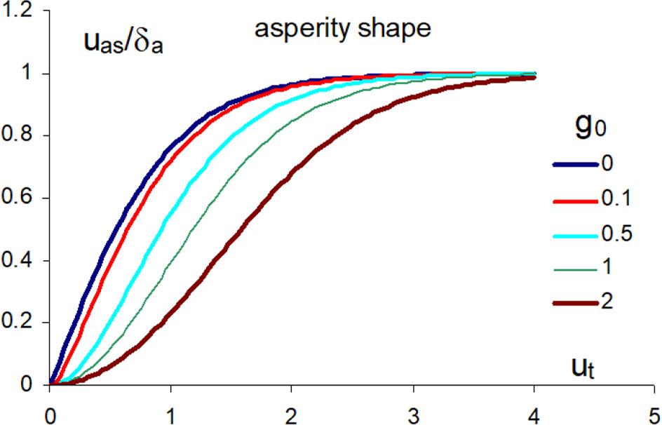
Figure 11
Shape of primary asperities depending on g0 parameter
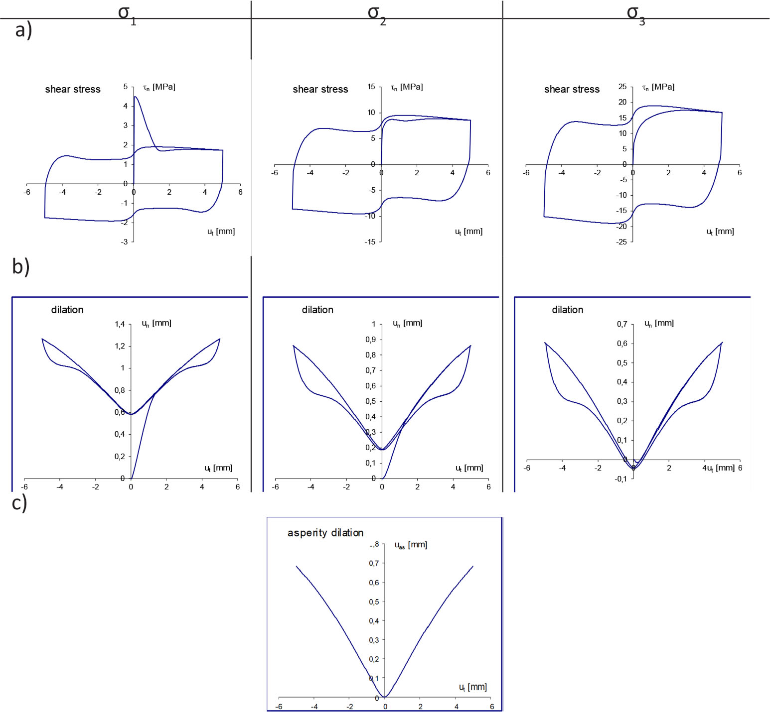
Figure 12
Simulation results for different normal loads (σ1 < σ2 < σ3, ρini = 2.3·103kg/m3, θmax = 25°, asperities) depending on the tangential displacement ut: a) variations of shear stress, b) variations of dilatancy, c) asperity shape assumed for calculations
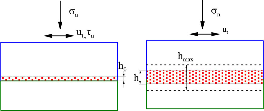
Figure 13
Third body granular layer generation due to cyclic loading
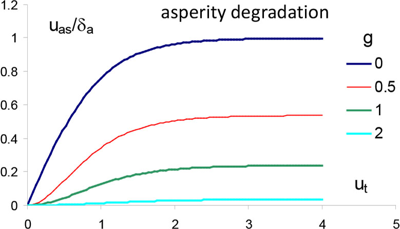
Figure 14
Evolution of asperity profile due to wear process
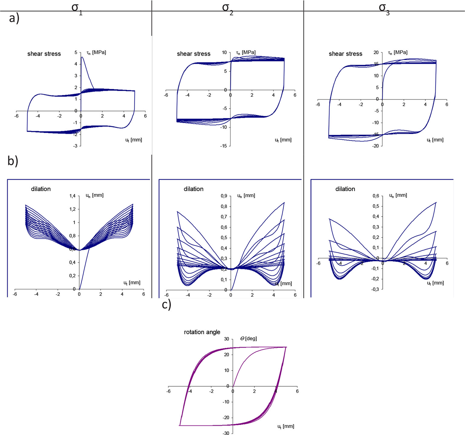
Figure 15
Simulation results for different normal loads (σ1 < σ2 < σ3, ρini = 2.3·103kg/m3, θmax = 25°, asperity degradation, interface layer frictional wear) depending on the tangential displacement ut: a) variations of shear stress, b) variations of dilatancy, c) variations of rotation angle θ
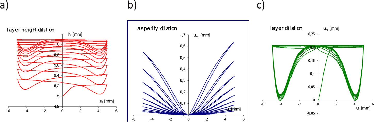
Figure 16
Supplement to simulation results given in Fig. 15 for normal load σn = 10 MPa: a) variations of contact layer height, b) asperity shape degradation, c) third body layer dilation
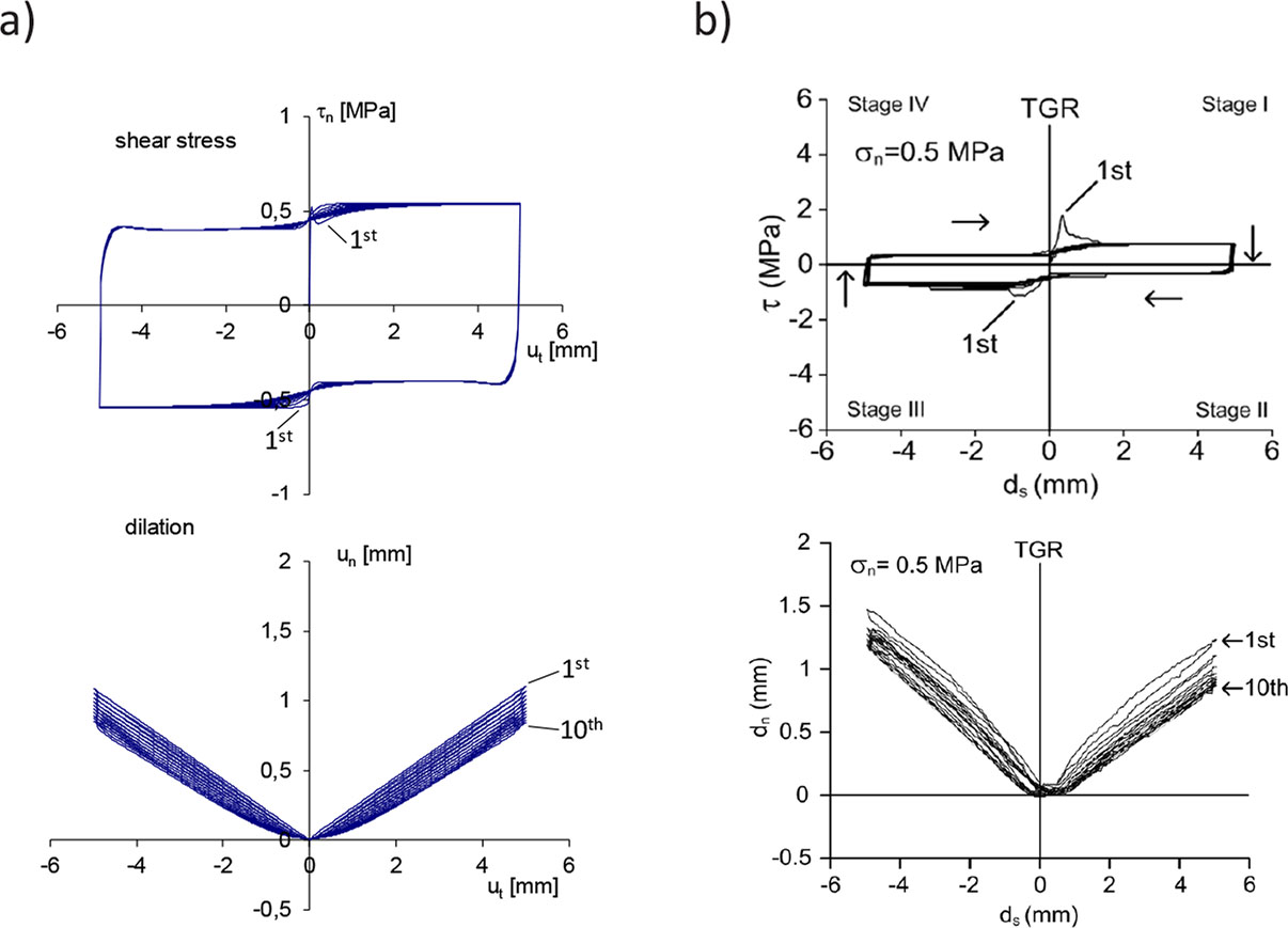
Figure 17
Simulation vs. experiment: a) simulation results, b) results obtained in experiment for normal load σn = 0.5 MPa
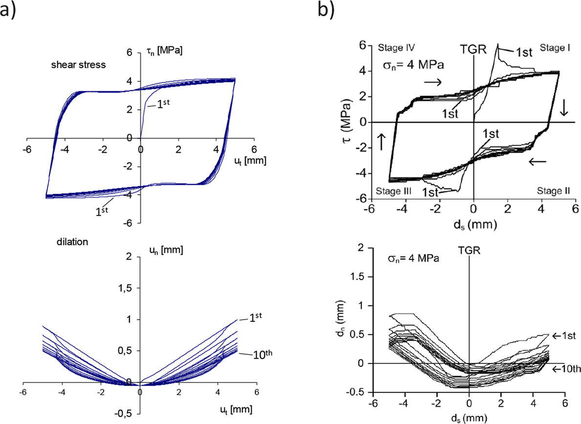
Figure 18
Simulation versus experiment: a) simulation results, b) results obtained in experiment for normal load σn = 4 MPa