
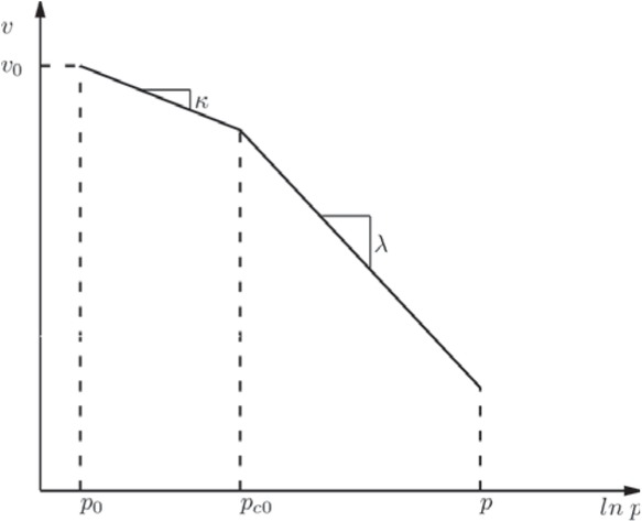
Figure 1
Schematic representation of the compressibility of a soil.
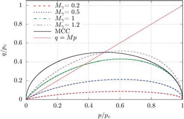
Figure 2
Shear yield surface hardening with plastic shear strains.
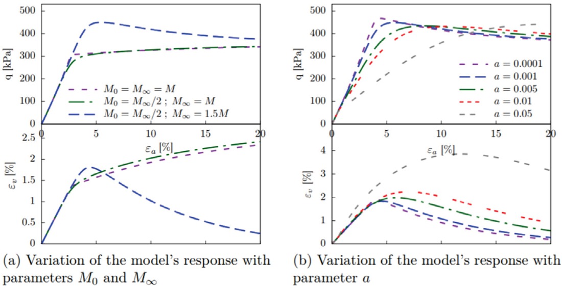
Figure 3
Response of a drained triaxial test.
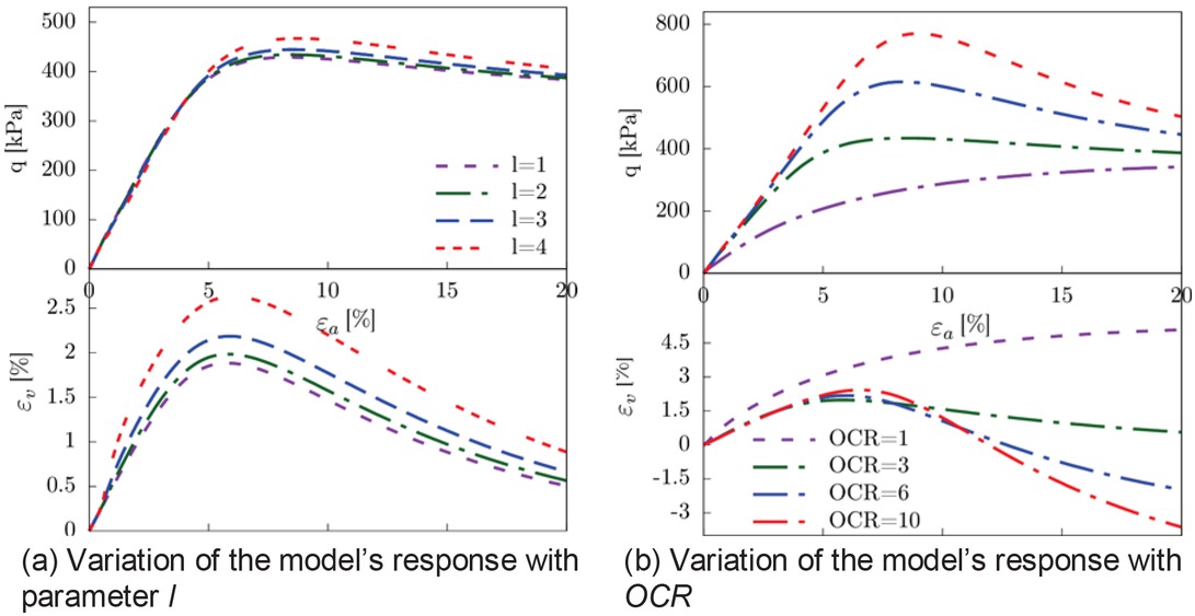
Figure 4
Response of a drained triaxial test.
Table 2
Studied models standardized formulation.
| MCC | CASM | SCSM | |
|---|---|---|---|
| α | ζ | ζ | (ζ,γ) |
| ϕ(p,α) | |||
| ψ(η,α) | |||
| Parameters | M | M,r,n,m | M∞,M0,a,M,l |
| η-ψ(η,α)>0 | m>1 | l>1 |
Table 3
MCC and SCSM parameters for different clays.
| Model parameter | ν | κ | λ | M | M0 | M∞ | a | l |
|---|---|---|---|---|---|---|---|---|
| London clay | 0.25 | 0.064 | 0.168 | 0.85 | 0.8 | 1.1 | 0.005 | 2 |
| Weald clay | 0.2 | 0.025 | 0.093 | 0.9 | 0.7 | 1.1 | 0.001 | 2 |
| Boom clay | 0.3 | 0.017 | 0.03 | 0.71 | 0.4 | 0.8 | 0.0025 | 2 |
Table 4
CASM parameters for different clays.
| Model parameter | r | n | m |
|---|---|---|---|
| London clay | 2.0 | 1.8 | 2.5 |
| Weald clay | 2.714 | 4.5 | 2.9 |
| Boom clay | 2.4 | 2.0 | 2.0 |
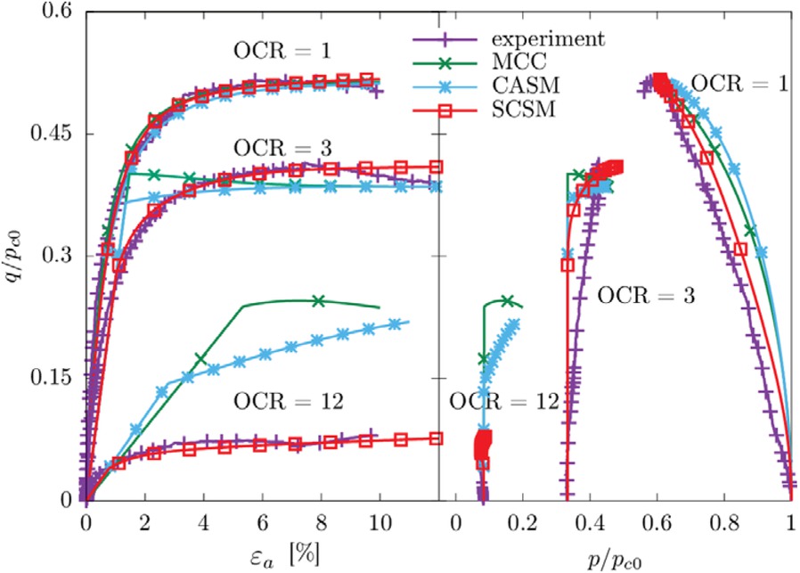
Figure 5
Simulation of undrained compression of London clay for normally consolidated and overconsolidated states.
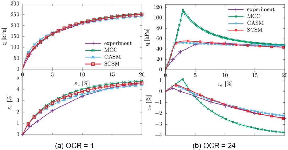
Figure 6
Simulation of drained compression of Weald clay for normally consolidated and overconsolidated states.
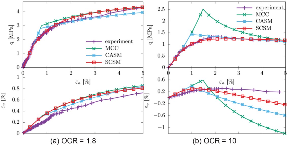
Figure 7
Simulation of drained compression of Boom clay for normally consolidated and overconsolidated states.
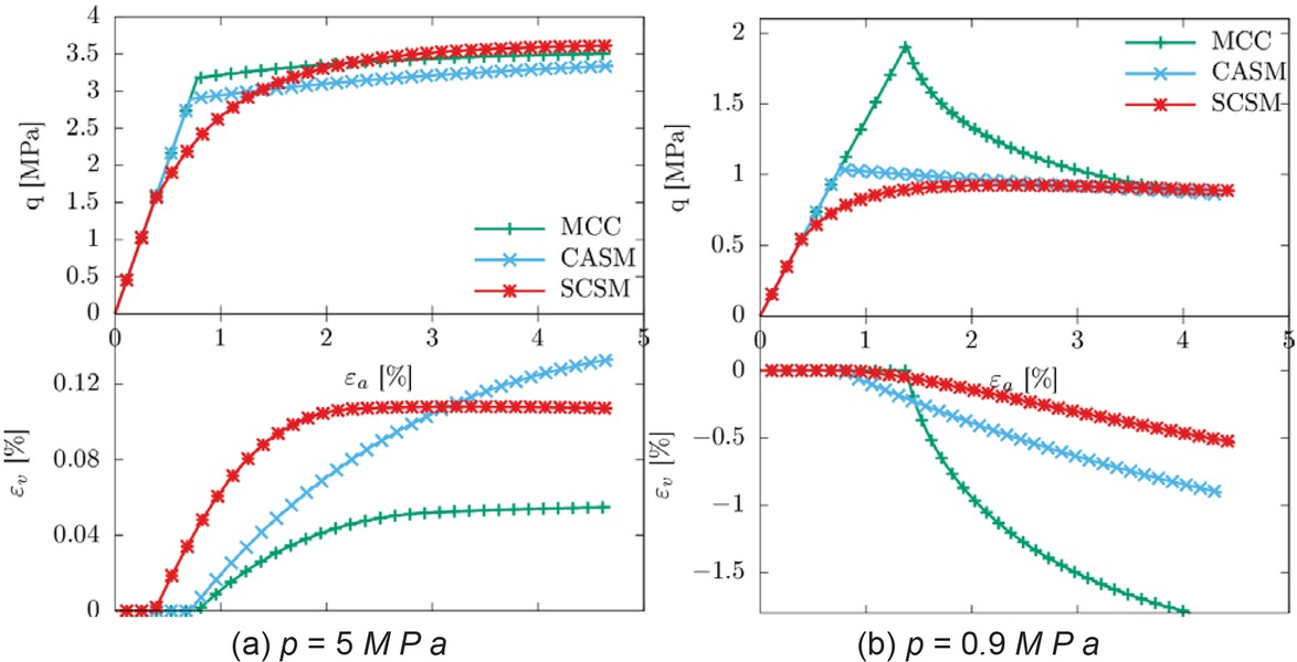
Figure 8
Simulation of pure triaxial shearing at constant effective pressure p.
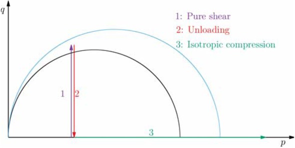
Figure 9
Loading path..
Table 5
MCC, SCSM and CASM parameters for the grey marl.
| MCC | SCSM | CASM | ||||||||
|---|---|---|---|---|---|---|---|---|---|---|
| ν | κ | λ | M | M0 | M∞ | a | l | r | n | m |
| 0.3 | 0.017 | 0.04 | 0.98 | 0.4 | 1.3 | 0.0017 | 2 | 1.8 | 3.5 | 3.0 |
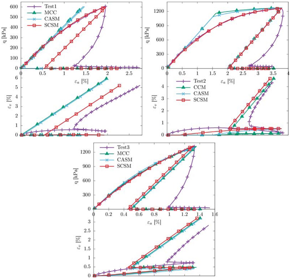
Figure 10
Simulation of specific stress controlled triaxial tests on a gray marl at different stress levels.
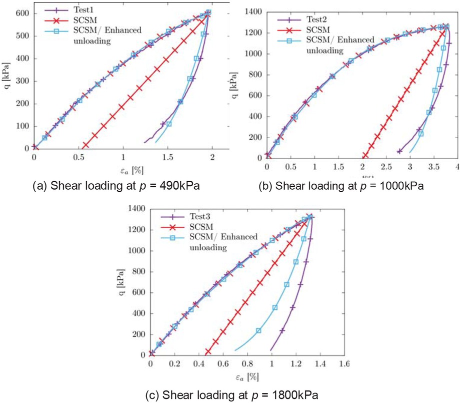
Figure 11
Enhancement of the unloading simulation.