
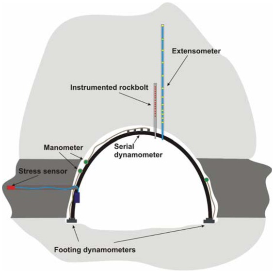
Figure 1
Overall scheme of the measurement station.
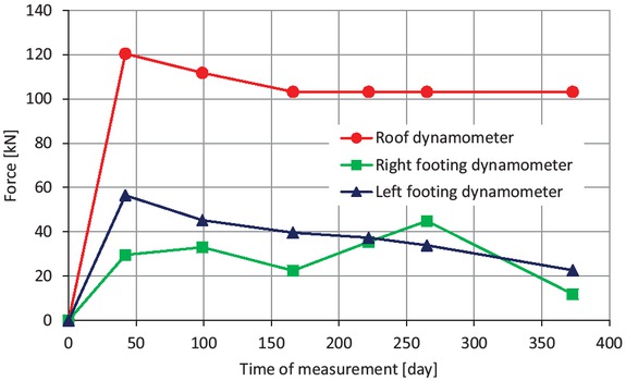
Figure 2
Distribution of forces in dynamometers – raise gallery Z-VII.
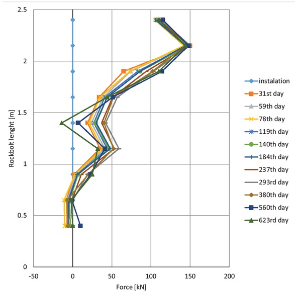
Figure 3
Force values in the instrumented rock bolt – airway crosscut W-1.
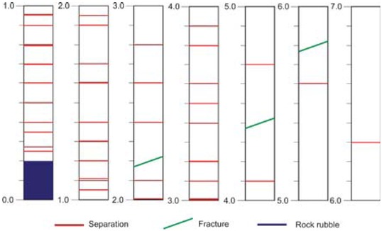
Figure 4
Results of endoscope test in the roof of C-1 cross-cut.
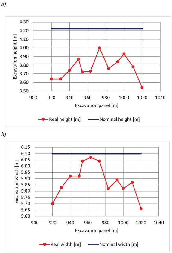
Figure 5
Change of height (A) and width (B) of yielding support arches in relation to nominal dimensions in the panel of airway cross-cut W-1.
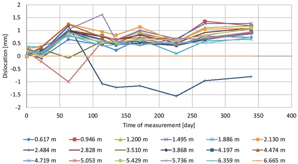
Figure 6
Dislocation of particular anchors in the roof of S bypass of IIz shaft.
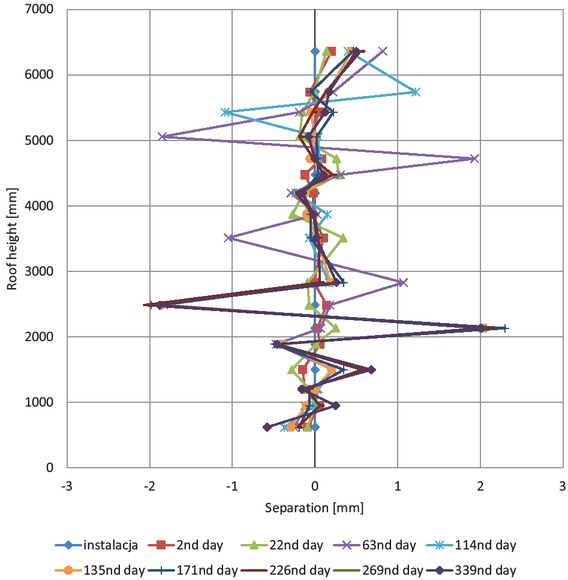
Figure 7
Roof separation of S bypass of Ilz shaft.
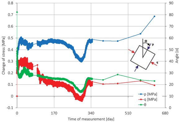
Figure 8
Change of values and orientation of principal stresses in Eastern guideline.
Table 1
Research results in monitored excavations.
| Parameters | Cross-cut C-1 | Eastern guideline | Airway cross-cut W-1 | Raise gallery Z-VII | Bypass S of IIz shaft | |
|---|---|---|---|---|---|---|
| Depth, m | 1,290 | 1,050 | 950 | 950 | 1,075 | |
| Rc roof, MPa | Penetrometer | 38.1 | 40.5 | 27.8 | 23.3 | 51.0 |
| Laboratory | 67.9 | 70.2 | 52.9 | 56.2 | 50.7 | |
| RQD, % | 6.6 | 43.7 | 14.6 | 13.7 | 85.4 | |
| Number of strata in roof | 13 | 12 | 9 | 3 | 6 | |
| Number of fractures in roof | 36 | 27 | 7 | 10 | 2 | |
| Range of crack zone, m | 6.5 | 8 | 0.7 | 4.7 | 1 | |
| Maximal force on dynamometers, kN | 187 | 222 | 299 | 120 | 0 | |
| Maximal tensile force in instrumented rock bolt, kN | 277 | 281 | 150 | 255 | 229 | |
| Maximal dislocation of extensometer anchors, mm | – | 60 | 72 | – | 1.6 | |
| Change of principal stresses, MPa | – | 0.8 | 0.61 | 1.44 | 0.44 | |
| Change in height and width of yielding | h | – | 0.01 | 0.46 | 0.27 | – |
| support arches in relation to nominal dimensions, m | w | 0.84 | 0.13 | 0.22 | 0.06 | – |
Table 2
Parameters used in the proposed methodology [19],
| Parameters | Comments |
|---|---|
| H – depth of excavation site, m; | |
| kr H– critical depth, m; | |
| Rc pen – penetrometric compressive strength, MPa; | |
| γ – specific weight of overlying strata. 0.027, MN/ m3; | |
| n – fracture intensiveness coefficient (– ); | |
| ls – number of fractures in roof (– ); | |
| l– number of strata in roof (–); w | |
| WL – roof lithology index( – ); | |
| hi – thickness of the ith rock layer, m; | |
| W L – n >0 | ri – reduction coefficient for the ith layer, related to lithology: sandstone – 1.0; siltstone – 0.77; claystone – 0.66; coal – 0.72. |
Table 3
Variants of possible support loading and deformation of mining excavations [19].
| Parameters | Variant | |||
|---|---|---|---|---|
| I | II | III | IV | |
| <1 | ≥1 | <1 | ≥1 | |
| WL – n | >0 | >0 | ≤0 | ≤0 |
| Final result | Possible insignificant loading and deformation of yielding arch support | Possible significant loading of roof bolting support | Possible significant loading and deformation of yielding arch support | Possible significant loading and deformation of yielding arch support and loading of roof bolting support |