
Table 1
Experimental conditions and elastic parameters of scaled railway ballast.
| σc | w | eo | κ | ν |
|---|---|---|---|---|
| [kPa] | [–] | [–] | [–] | |
| 15 | Dry | 0.774 | 0.0027 | 0.30 |
| 25 | 0.801 | 0.0027 | 0.30 | |
| 60 | 0.759 | 0.0027 | 0.30 | |
| 115 | 0.771 | 0.0027 | 0.30 | |
| 200 | 0.774 | 0.0027 | 0.30 | |
| 15 | Saturated | 0.787 | 0.0027 | 0.30 |
| 20 | 0.781 | 0.0027 | 0.30 |
Table 2
Experimental conditions and elastic parameters of fouled railway ballast.
| σc | w | eo | κ | ν |
|---|---|---|---|---|
| [kPa] | [–] | [–] | [–] | |
| 30 | 4.0 | 0.350 | 0.0013 | 0.27 |
| 100 | 4.0 | 0.350 | 0.0015 | 0.27 |
| 200 | 4.0 | 0.350 | 0.0020 | 0.27 |
| 400 | 4.0 | 0.350 | 0.0030 | 0.27 |
| 100 | 12.0 | 0.350 | 0.0018 | 0.27 |
| 400 | 12.0 | 0.350 | 0.0045 | 0.27 |
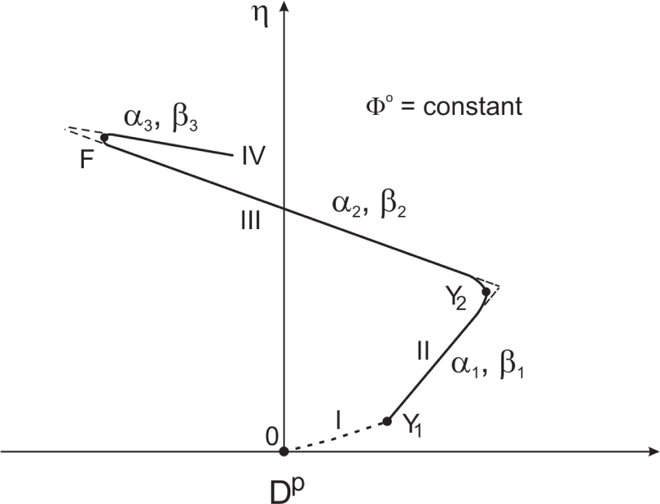
Figure 1
Scheme of stress ratio–plastic dilatancy relationship.
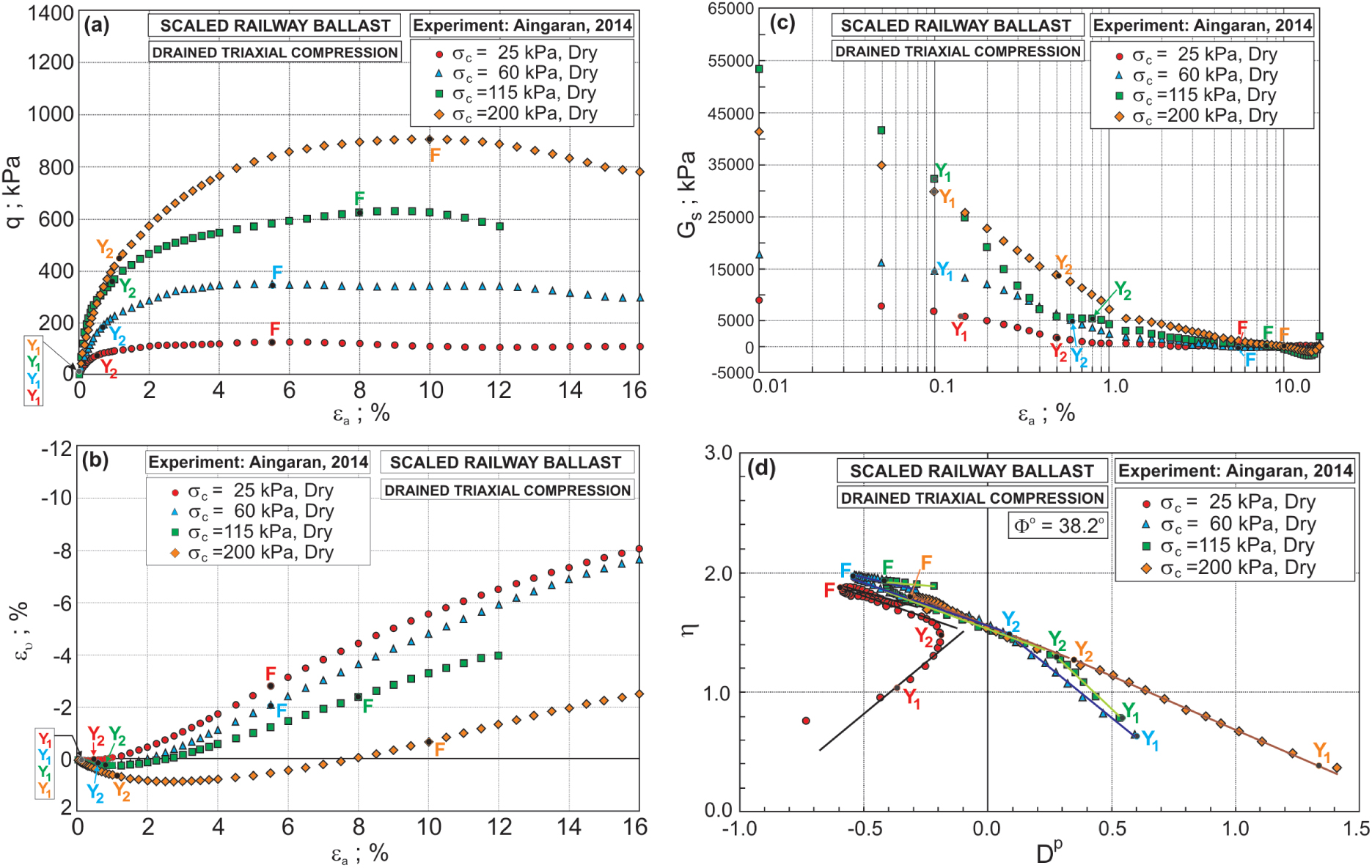
Figure 2
Relationships for dry scaled ballast: (a) q–εa; (b) ευ–εa; (c) Gs–εa; and (d) η–Dp.
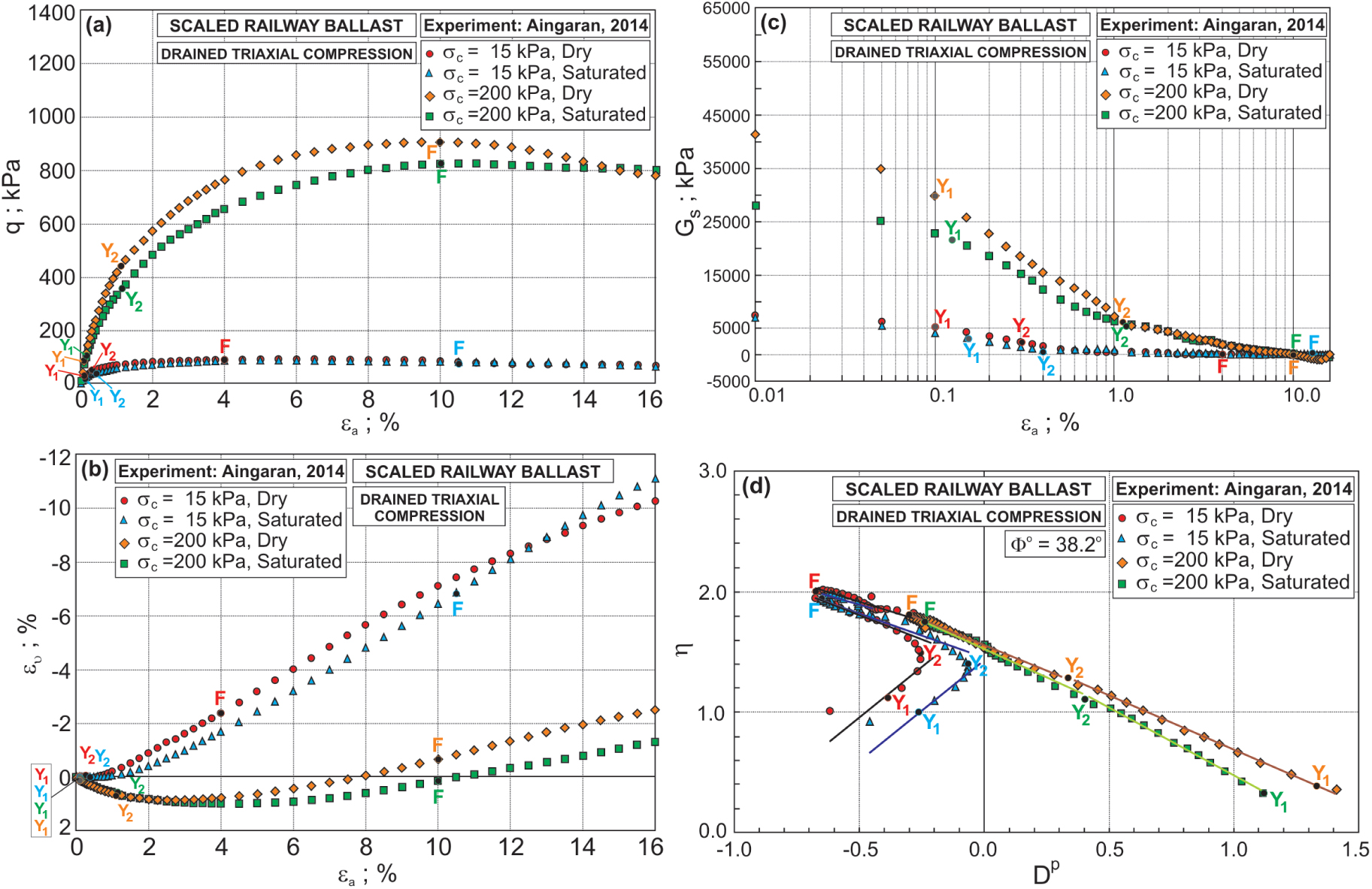
Figure 3
Relationships for saturated scaled ballast: (a) q–εa; (b) ευ–εa; (c) Gs–εa; and (d) η–Dp.
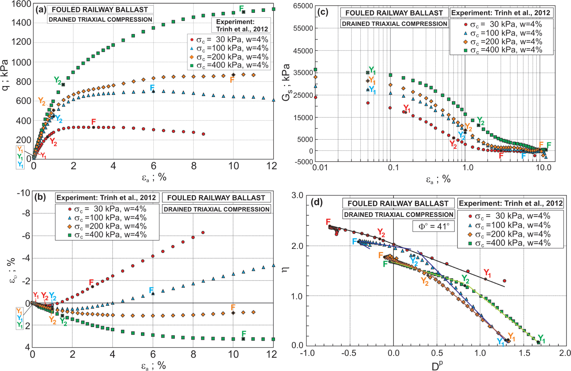
Figure 4
Relationships for fouled ballast at 4% water content: (a) q–εa; (b) ευ–εa; (c) Gs–εa; and (d) η–Dp.
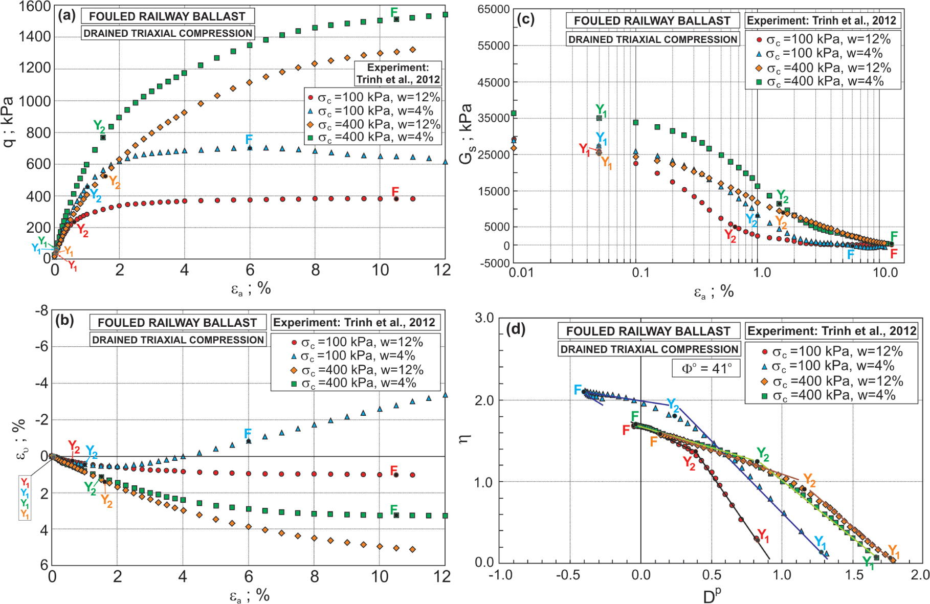
Figure 5
Relationships for fouled ballast at 4% and 12% water contents: (a) q–εa; (b) ευ–εa; (c) Gs–εa; and (d) η–Dp.
Table 3
Characteristic points and stress–dilatancy parameters for scaled railway ballast.
| σc | w | εa [%] | Parameters α and β | |||||||
|---|---|---|---|---|---|---|---|---|---|---|
| [kPa] | Y1 | Y2 | F | α1 | β1 | α2 | β2 | α3 | β3 | |
| 15 | Dry | 0.10 | 0.30 | 4.00 | –0.70 | –3.5 | 0.28 | 1.60 | –0.10 | 1.30 |
| 25 | 0.15 | 0.50 | 5.50 | –0.30 | –3.5 | 0.22 | 1.50 | 0.00 | 1.20 | |
| 60 | 0.10 | 0.60 | 5.50 | –0.15 | 3.5 | 0.00 | 1.50 | –0.35 | 1.00 | |
| 115 | 0.10 | 0.90 | 8.00 | –0.65 | 4.2 | 0.05 | 1.60 | –0.63 | 0.30 | |
| 200 | 0.10 | 1.1 | 10.00 | –0.10 | 1.9 | 0.00 | 1.80 | –0.00 | 1.80 | |
| 15 | Saturated | 0.15 | 0.40 | 10.50 | 0.25 | –3.5 | 0.20 | 1.50 | –0.05 | 1.30 |
| 200 | 0.12 | 1.15 | 10.00 | 0.05 | 2.2 | –0.15 | 2.05 | 0.00 | 1.50 | |
Table 4
Characteristic points and stress–dilatancy parameters for fouled railway ballast.
| σc | w | εa [%] | Parameters α and β | |||||||
|---|---|---|---|---|---|---|---|---|---|---|
| [kPa] | [%] | Y1 | Y2 | F | α1 | β1 | α2 | β2 | α3 | β3 |
| 30 | 4.0 | 0.16 | 0.70 | 3.0 | –0.80 | 1.50 | –0.90 | 1.00 | 0.00 | 2.20 |
| 100 | 4.0 | 0.05 | 1.00 | 6.0 | –1.60 | 4.00 | –0.70 | 0.60 | 0.00 | 2.20 |
| 200 | 4.0 | 0.05 | 1.00 | 10.0 | –0.90 | 3.40 | –0.08 | 1.50 | 0.00 | 2.20 |
| 400 | 4.0 | 0.05 | 1.50 | 10.5 | –1.70 | 3.20 | 0.00 | 1.20 | 0.00 | 1.20 |
| 100 | 12.0 | 0.05 | 0.65 | 10.5 | –1.50 | 5.70 | 0.00 | 1.90 | 0.00 | 1.90 |
| 400 | 12.0 | 0.05 | 1.60 | – | –2.30 | 3.40 | 0.00 | 1.30 | – | – |