
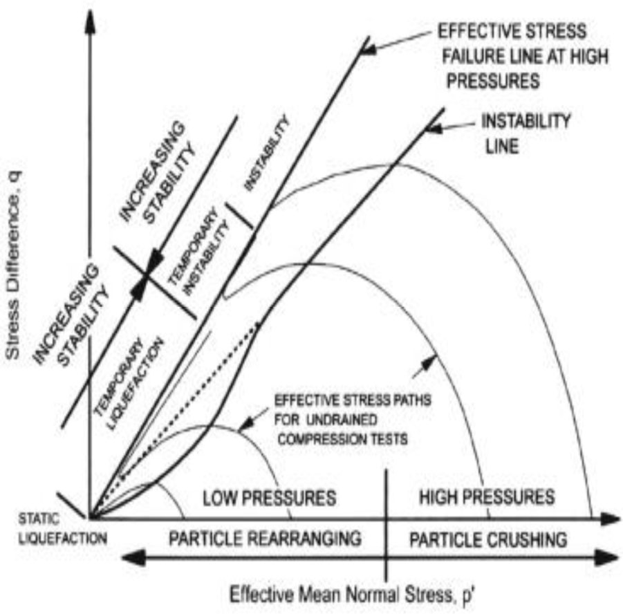
Figure 1
Determination of the instability line (Yamamuro and Lade, 1997).
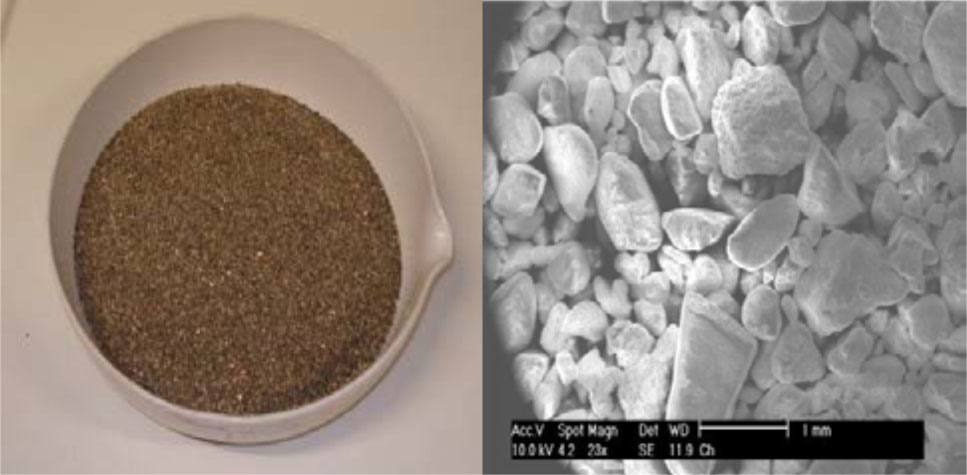
Figure 2
(a) Photograph and (b) SEM image of Chlef sand (Algeria).
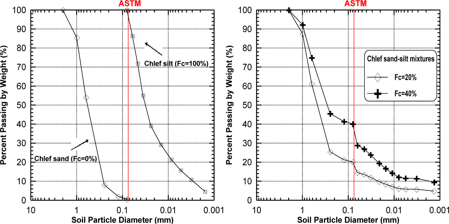
Figure 3
Grain size distribution curves of tested soils.
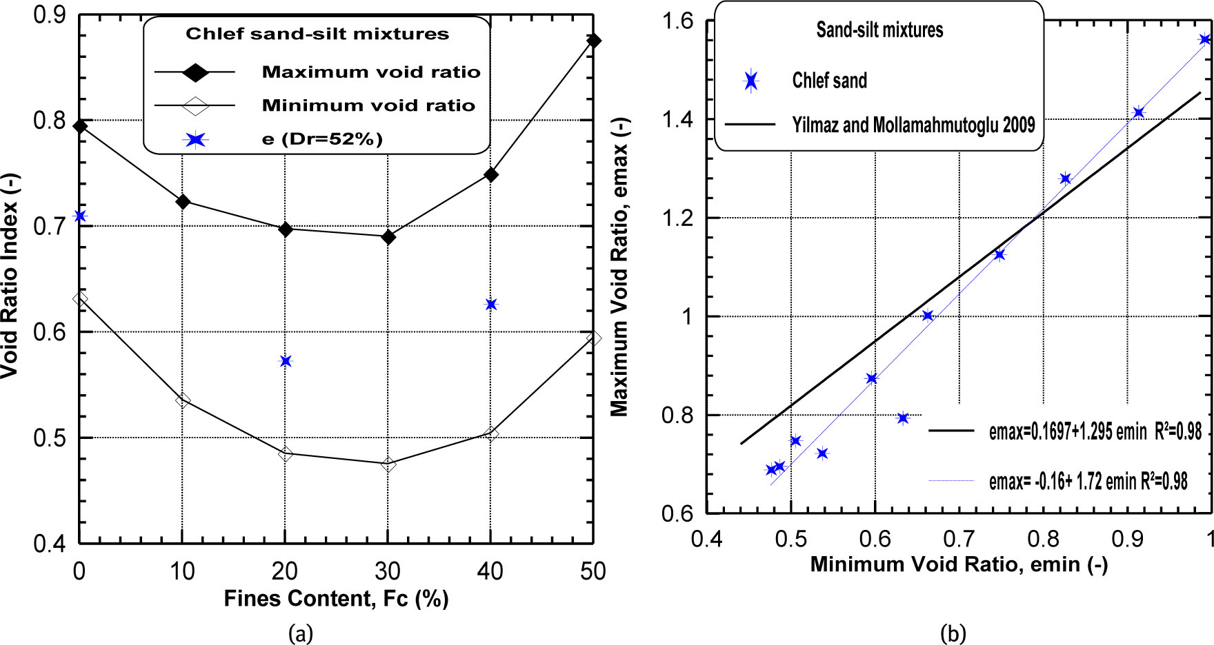
Figure 4
Void ratios index of tested soils. (a) Void ratio index versus fines content and (b) maximum void ratio versus minimum void ratio.
Table 1
Index properties of sand and silt under study.
| Properties | Materials Chlef sand | Silt |
|---|---|---|
| Gs | 2.652 | 2.667 |
| Dmax(mm) | 2.000 | 0.08 |
| D10 (mm) | 0.266 | - |
| D50 (mm) | 0.596 | 0.023 |
| Cu (.) | 2.634 | |
| Cc (.) | 0.999 | |
| emax(.) | 0.795 | 1.563 |
| emin(.) | 0.632 | 0.991 |
| WL(%) | - | 31.72 |
| Wp (%) | - | 26.71 |
| Ip (%) | - | 5.12 |
| USCS | SP | ML |
| Grain Shape | Rounded | Rounded |
Table 2
Index properties of Chlef sand-silt mixtures.
| Properties | Sand-silt mixtures | |
|---|---|---|
| Fc (%) | 20 | 40 |
| Gs | 2.655 | 2.658 |
| D10(mm) | 0.023 | 0.003 |
| D50(mm) | 0.488 | 0.236 |
| Cu (.) | 27.24 | 120.51 |
| Cc(.) | 3.997 | 3.300 |
| emax(.) | 0.697 | 0.759 |
| emin(.) | 0.458 | 0.505 |
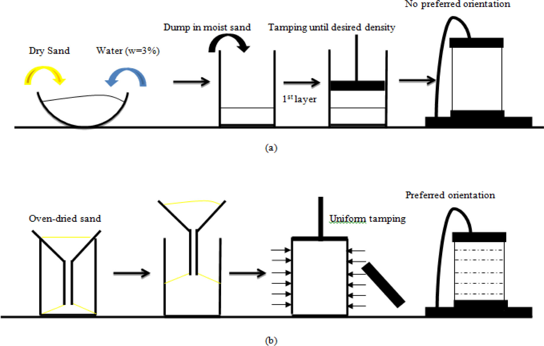
Figure 5
Schematic illustration of sample preparation; (a) wet deposition and (b) dry funnel pluviation.
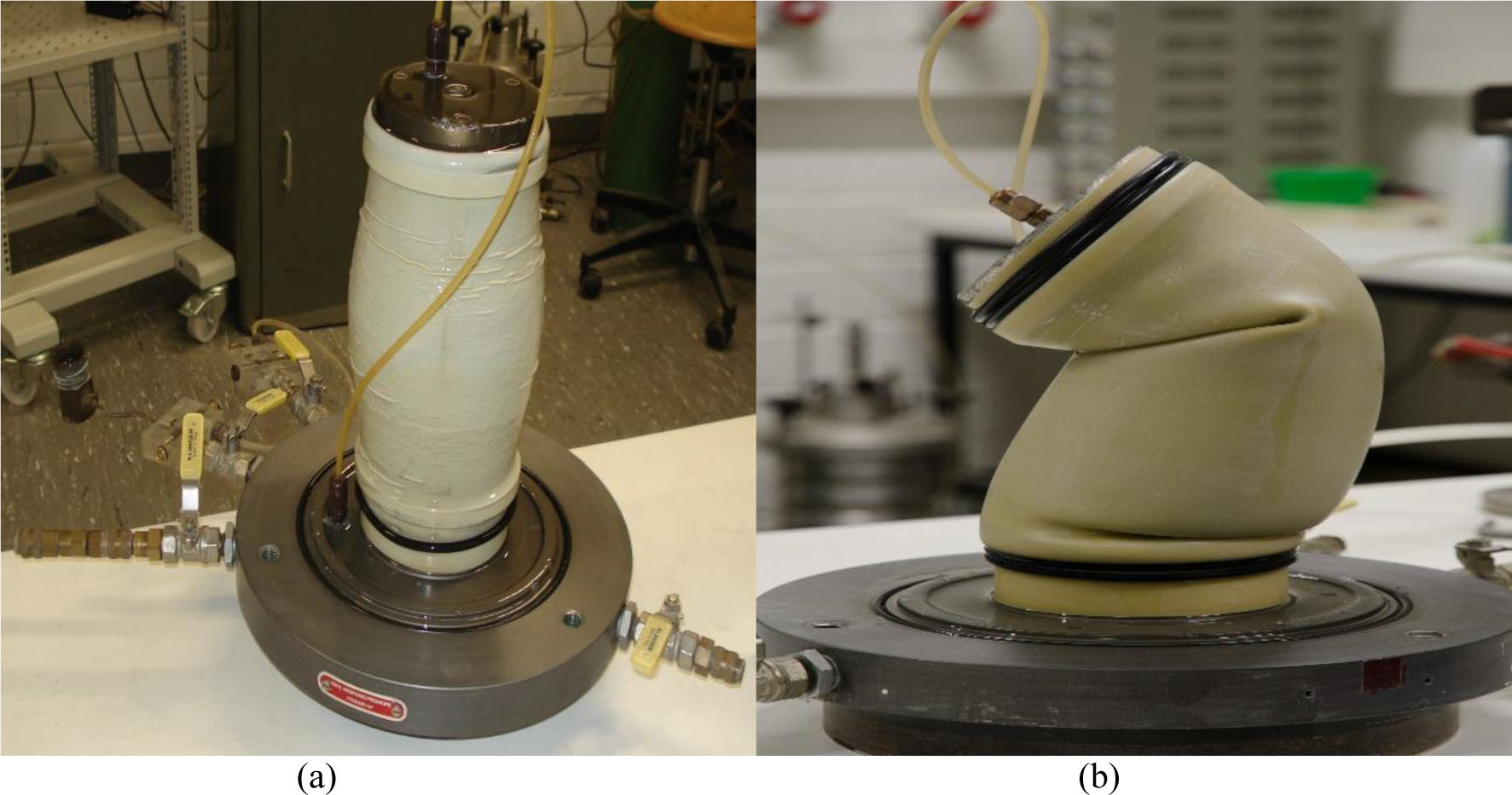
Figure 6
View of (a) dry funnel pluviated and (b) wet deposited samples after shearing.
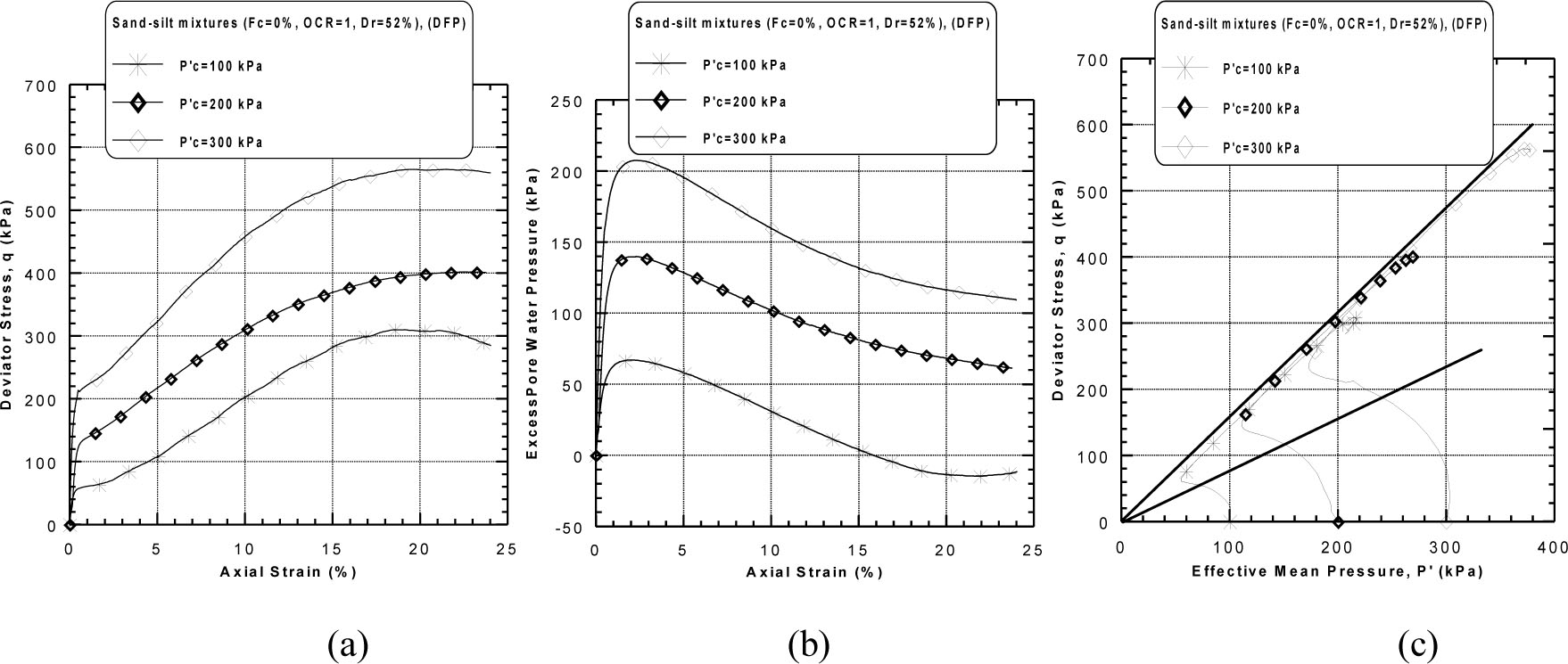
Figure 7
Undrained monotonic response of dry funnel pluviated sand–silt mixtures (Fc = 0%, OCR = 1, Dr = 52 %): (a) deviator stress versus axial strain, (b) excess pore water pressure versus axial strain and (c) stress path diagram.
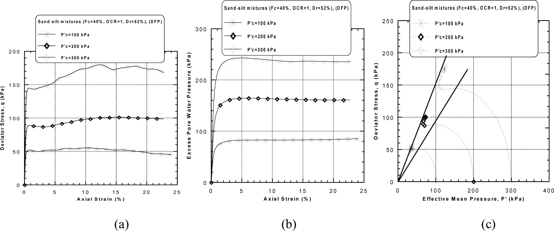
Figure 8
Undrained monotonic response of dry funnel pluviated sand–silt mixtures (Fc = 40%, OCR = 1, Dr = 52%): (a) deviator stress versus axial strain, (b) excess pore water pressure versus axial strain and (c) stress path diagram.
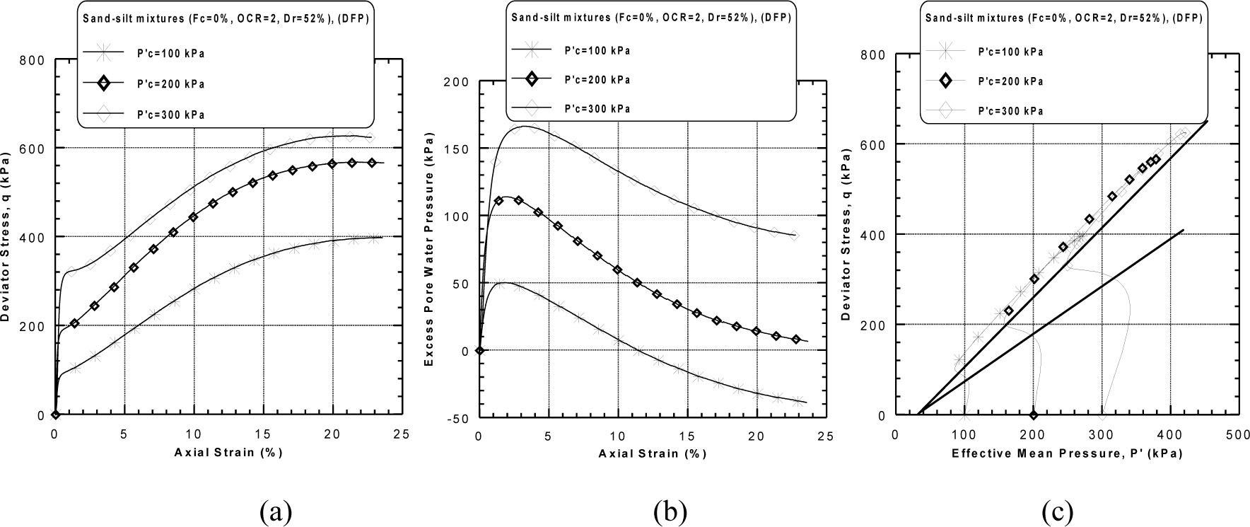
Figure 9
Undrained monotonic response of dry funnel pluviated sand–silt mixtures (Fc = 0%, OCR = 2, Dr = 52%): (a) deviator stress versus axial strain, (b) excess pore water pressure versus axial strain and (c) stress path diagram.
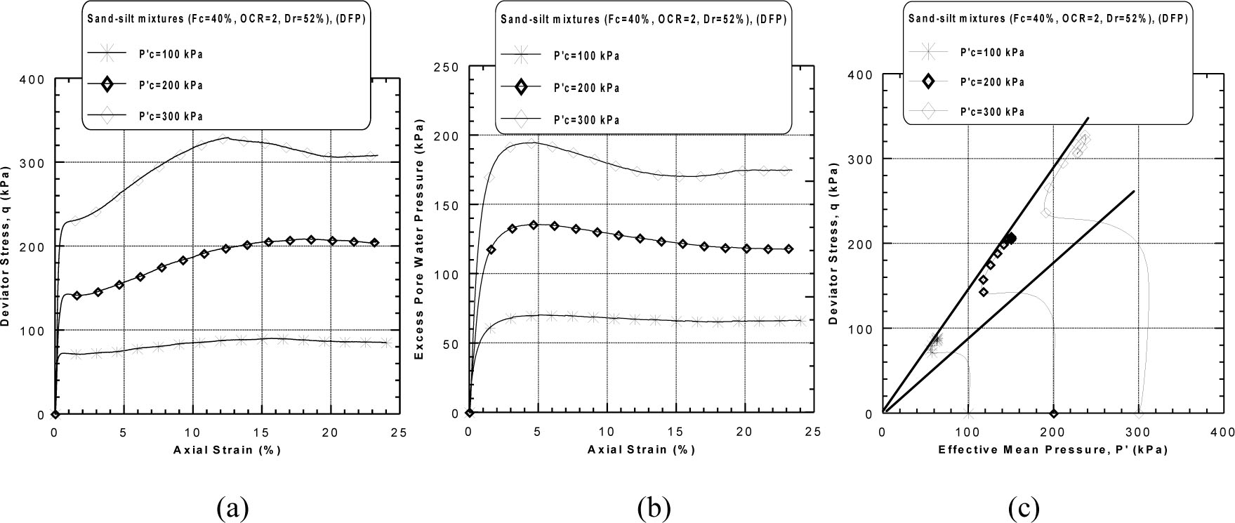
Figure 10
Undrained monotonic response of dry funnel pluviated sand–silt mixtures (Fc = 40%, OCR = 2, Dr = 52%): (a) deviator stress versus axial strain, (b) excess pore water pressure versus axial strain and (c) stress path diagram.
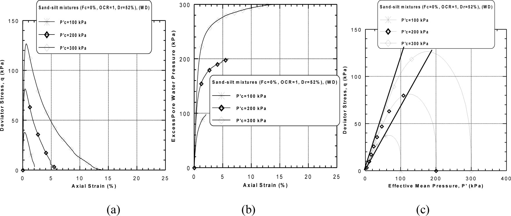
Figure 11
Undrained monotonic response of wet deposited sand–silt mixtures (Fc = 0%, OCR = 1, Dr = 52%): (a) deviator stress versus axial strain, (b) excess pore water pressure versus axial strain and (c) stress path diagram.
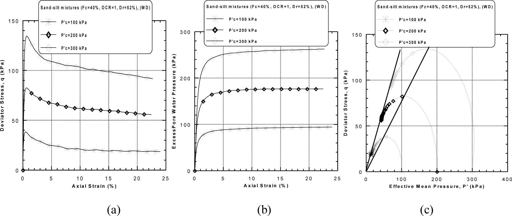
Figure 12
Undrained monotonic response of wet deposited sand–silt mixtures (Fc = 40%, OCR = 1, Dr = 52%): (a) deviator stress versus axial strain, (b) excess pore water pressure versus axial strain and (c) stress path diagram.
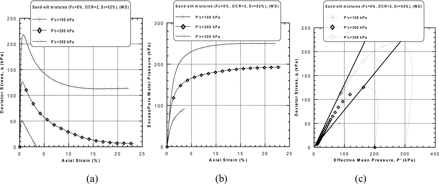
Figure 13
Undrained monotonic response of wet deposited sand–silt mixtures (Fc = 0%, OCR = 2, Dr = 52%): (a) deviator stress versus axial strain, (b) excess pore water pressure versus axial strain and (c) stress path diagram.
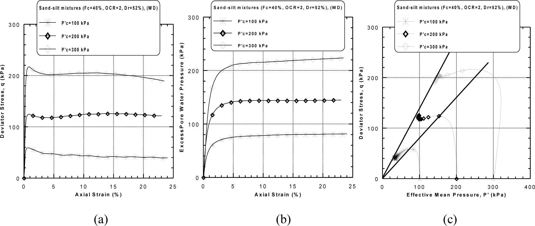
Figure 14
Undrained monotonic response of wet deposited sand–silt mixtures (Fc = 40%, OCR = 2, Dr = 52%): (a) deviator stress versus axial strain, (b) excess pore water pressure versus axial strain and (c) stress path diagram.
Table 3
Summary of monotonic triaxial tests of silty sand.
| Test No | Dr (%) | Fc (%) | Method | OCR | P’c (kPa) | η | ϕ’ins(°) | ϕ’s(°) | qins(kPa) | P’ins(kPa) |
|---|---|---|---|---|---|---|---|---|---|---|
| 1 | 100 | 55.56 | 56.11 | |||||||
| 2 | 1 | 200 | 1.01 | 45.28 | 25.61 | 136.77 | 138.14 | |||
| 3 | DFP | 300 | 219.72 | 21.92 | ||||||
| 4 | 100 | 86.34 | 94.97 | |||||||
| 5 | 2 | 200 | 1.10 | 47.73 | 27.70 | 1 79.88 | 197.87 | |||
| 6 | 0 | 300 | 307,45 | 338,19 | ||||||
| 7 | 100 | 34.26 | 20.90 | |||||||
| 8 | 1 | 200 | 0.61 | 31.38 | 16.07 | 78.24 | 47.72 | |||
| 9 | WD | 300 | 125.96 | 76.83 | ||||||
| 10 | 100 | 51.46 | 37.36 | |||||||
| 11 | 2 | 200 | 0.72 | 36.01 | 18.75 | 122.01 | 88.58 | |||
| 12 | 300 | 208.06 | 151.05 | |||||||
| 13 | 100 | 51.48 | 39.12 | |||||||
| 14 | 1 | 200 | 0.65 | 37.47 | 19.85 | 98.89 | 75.15 | |||
| 15 | DFP | 3 00 | 1 42.67 | 108.43 | ||||||
| 16 | 100 | 23.51 | 63.64 | 58.93 | ||||||
| 17 | 2 | 2 00 | 0.93 | 42.82 | 142.05 | 131.54 | ||||
| 18 | 20 | 300 | 236.87 | 219.34 | ||||||
| 19 | 52 | 100 | 35.02 | 24.16 | ||||||
| 20 | 1 | 200 | 0.69 | 34.60 | 18.02 | 79.31 | 54.72 | |||
| 21 | WD | 300 | 128.19 | 88.45 | ||||||
| 22 | 100 | 52.11 | 40.12 | |||||||
| 23 | 2 | 200 | 0.77 | 37.59 | 19.95 | 126.16 | 97.14 | |||
| 24 | 300 | 211.95 | 163.20 | |||||||
| 25 | 100 | 48.58 | 36.43 | |||||||
| 26 | 1 | 200 | 0.75 | 36.87 | 19.47 | 86.78 | 65.08 | |||
| 27 | DFP | 300 | 139.97 | 104.98 | ||||||
| 28 | 100 | 59.78 | 49.01 | |||||||
| 29 | 2 | 200 | 0.83 | 39.58 | 21.14 | 138.05 | 113.20 | |||
| 30 | 40 | 300 | 227.03 | 186.16 | ||||||
| 31 | 100 | 36.33 | 26.16 | |||||||
| 32 | 1 | 200 | 0.72 | 35.75 | 18.75 | 81.89 | 58.96 | |||
| 33 | 300 | 131.05 | 94.36 | |||||||
| 34 | WD | 100 | 55.34 | 42.94 | ||||||
| 35 | 2 | 200 | 0.78 | 37.83 | 20.12 | 129.75 | 100.68 | |||
| 36 | 300 | 214.43 | 166.40 |
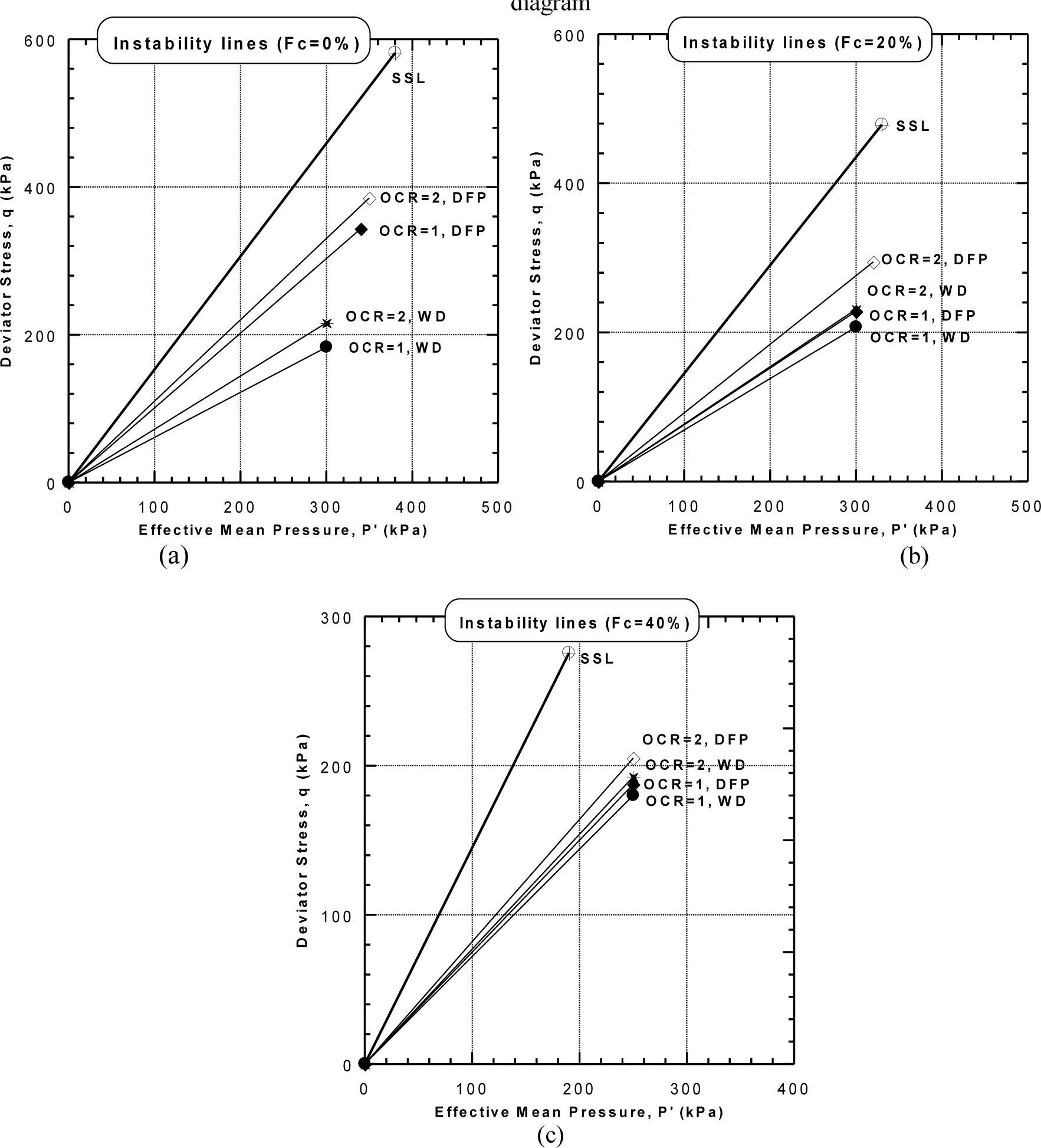
Figure 15
Instability and steady-state lines of Chlef sand–silt mixtures = (Dr = 52%): (a) Fc = 0%, (b) Fc = 20% and(c) Fc = 40%.
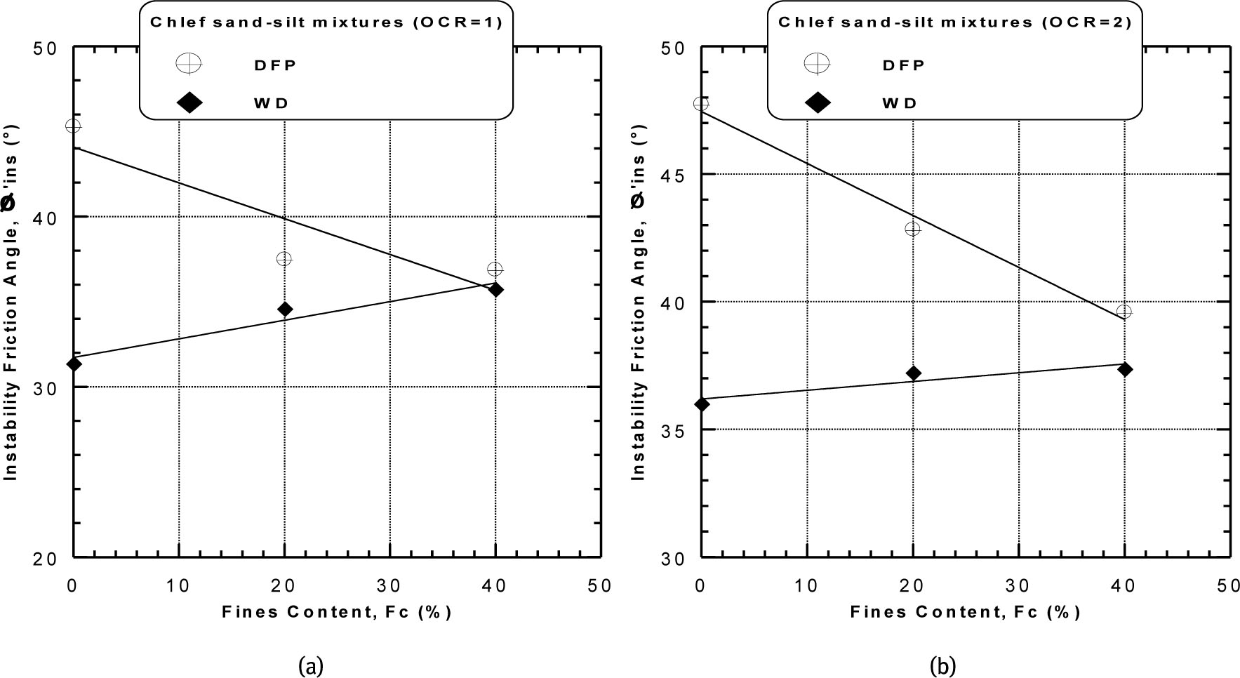
Figure 16
Instability friction angles versus fines content of sand–silt mixtures (Dr = 52%): (a) OCR = 1 and (b) OCR = 2.
Table 4
Coefficients a, b and R2 for equation (2).
| Methods | DFP | WD | ||
|---|---|---|---|---|
| OCR | 1 | 2 | 1 | 2 |
| a | 44.08 | 47.44 | 31.72 | 36.19 |
| b | –0.21 | –0.20 | 0.11 | 0.03 |
| R2 | 0.80 | 0.99 | 0.93 | 0.83 |
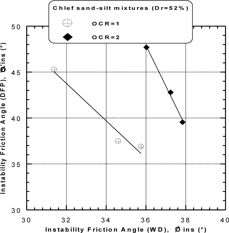
Figure 17
DFP instability friction angle versus WD friction angle of Chlef sand–silt mixtures (Dr = 52%).
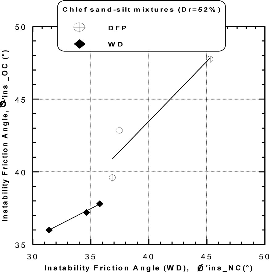
Figure 18
Overconsolidated instability friction angle versus normally consolidated friction angle of sand–silt mixtures (Dr = 52%).
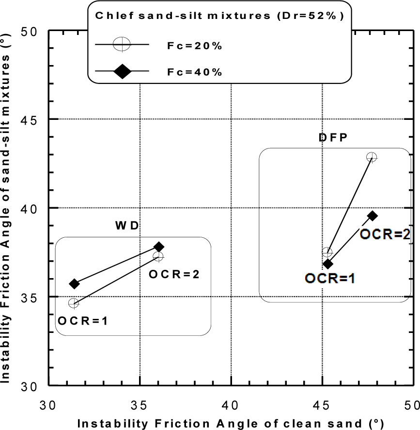
Figure 19
Instability friction angle of sand–silt mixtures versus instability friction angle of sand (Dr = 52%).
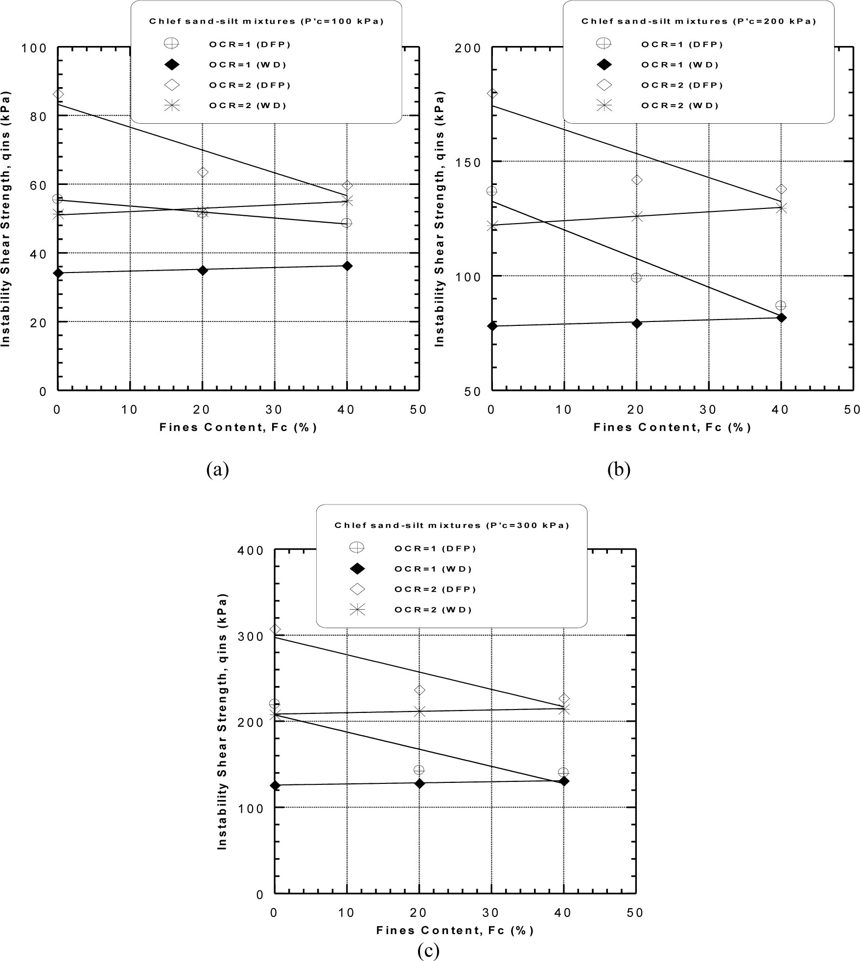
Figure 20
Instability shear strength of sand–silt mixtures versus fines content (Dr = 52%): (a) P’c = 100 kPa;(b) P’c = 200 kPa; (c) P’c = 300 kPa.
Table 7
Coefficients a, b and R2 for equation (5).
| P’c (kPa) | 100 | 200 | 300 | ||||||||||
|---|---|---|---|---|---|---|---|---|---|---|---|---|---|
| Method | DFP | WD | DFP | WD | DFP | WD | |||||||
| OCR | 1 | 2 | 1 | 2 | 1 | 2 | 1 | 2 | 1 | 2 | 1 | 2 | |
| a | 55.4 | 83.2 | 34.2 | 51.0 | 132.5 | 174.2 | 78.0 | 122.1 | 207.3 | 297.3 | 125.9 | 208.3 | |
| b | –0.17 | –0.66 | 0.05 | 0.097 | –1.25 | –1.04 | 0.09 | 0.19 | –1.99 | –2.01 | 0.13 | 0.16 | |
| R2 | 0.99 | 0.86 | 0.98 | 0.87 | 0.92 | 0.82 | 0.95 | 0.99 | 0.78 | 0.84 | 0.99 | 0.98 |
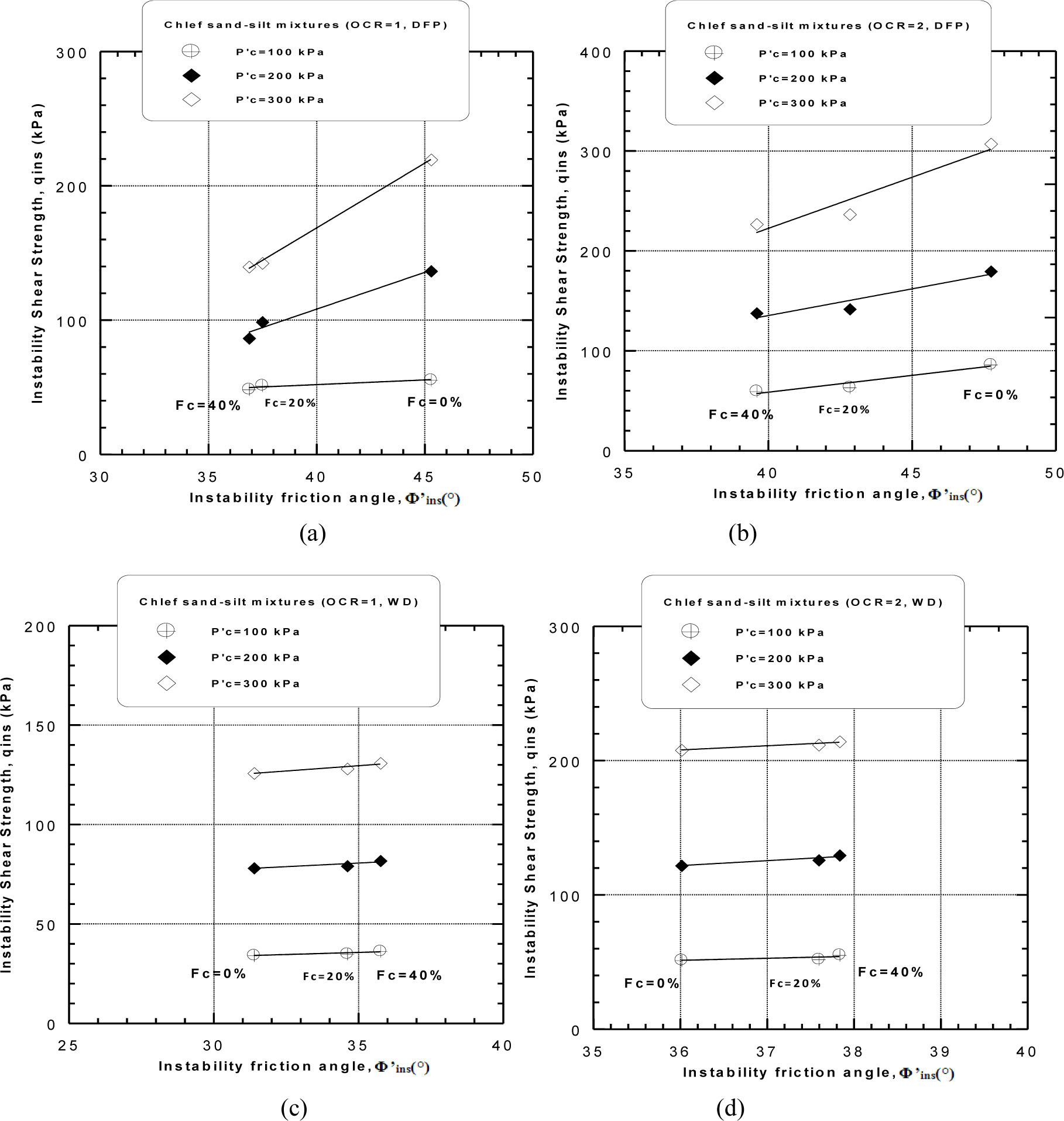
Figure 21
Instability shear strength versus the instability friction angle of sand-silt mixtures (Dr = 52%): (a) OCR = 1, DFP; (b) OCR = 2, DFP; (c) OCR = 1, WD; (d) OCR = 2, WD.
Table 8
Coefficients a, b and R2 for equation (6).
| Method | DFP | WD | ||||||||||
|---|---|---|---|---|---|---|---|---|---|---|---|---|
| OCR | 1 | 2 | 1 | 2 | ||||||||
| P’c (kPa) | 100 | 200 | 300 | 100 | 200 | 300 | 100 | 200 | 300 | 100 | 200 | 300 |
| a | 24.01 | 110.8 | 216.8 | 76.24 | 78.36 | 186.7 | 20.88 | 55.18 | 92.37 | –3.15 | 10.18 | 95.39 |
| b | 0.70 | 5.74 | 9.64 | 3.37 | 5.34 | 10.23 | 0.42 | 0.73 | 1.06 | 1.51 | 3.66 | 3.12 |
| R2 | 0.88 | 0.97 | 0.99 | 0.93 | 0.90 | 0.92 | 0.83 | 0.77 | 0.89 | 0.52 | 0.88 | 0.93 |
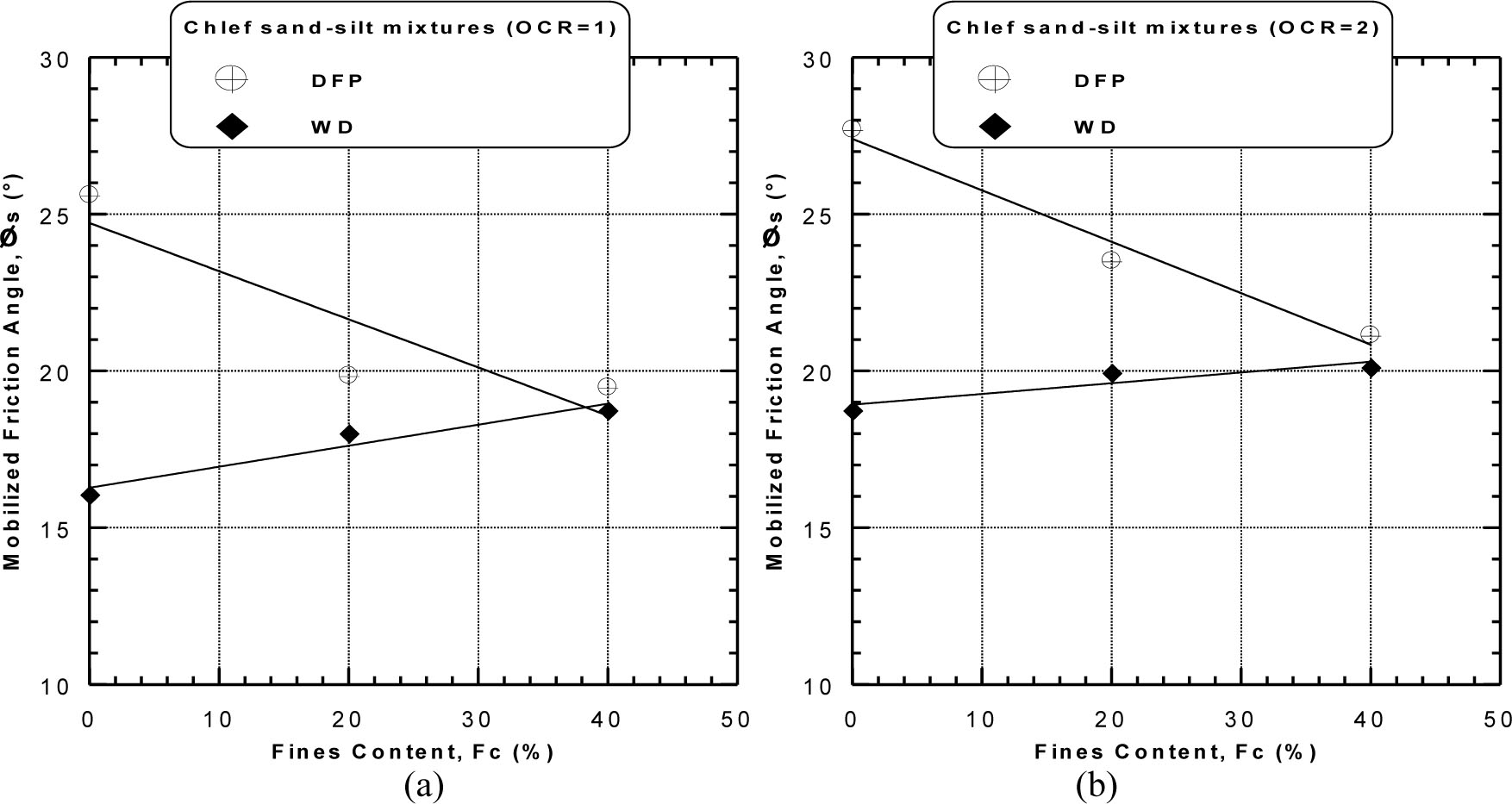
Figure 22
Mobilised friction angles versus fines content of sand–silt mixtures (Dr = 52%): (a) OCR = 1 and (b) OCR = 2.
Table 9
Coefficients a, b and R2 for equation (7).
| Methods | DFP | WD | ||
|---|---|---|---|---|
| OCR | 1 | 2 | 1 | 2 |
| a | 24.71 | 27.39 | 16.27 | 18.92 |
| b | – 0.15 | – 0.16 | 0.0 6 7 | 0.03 |
| R2 | 0.80 | 0.97 | 0.94 | 0.84 |
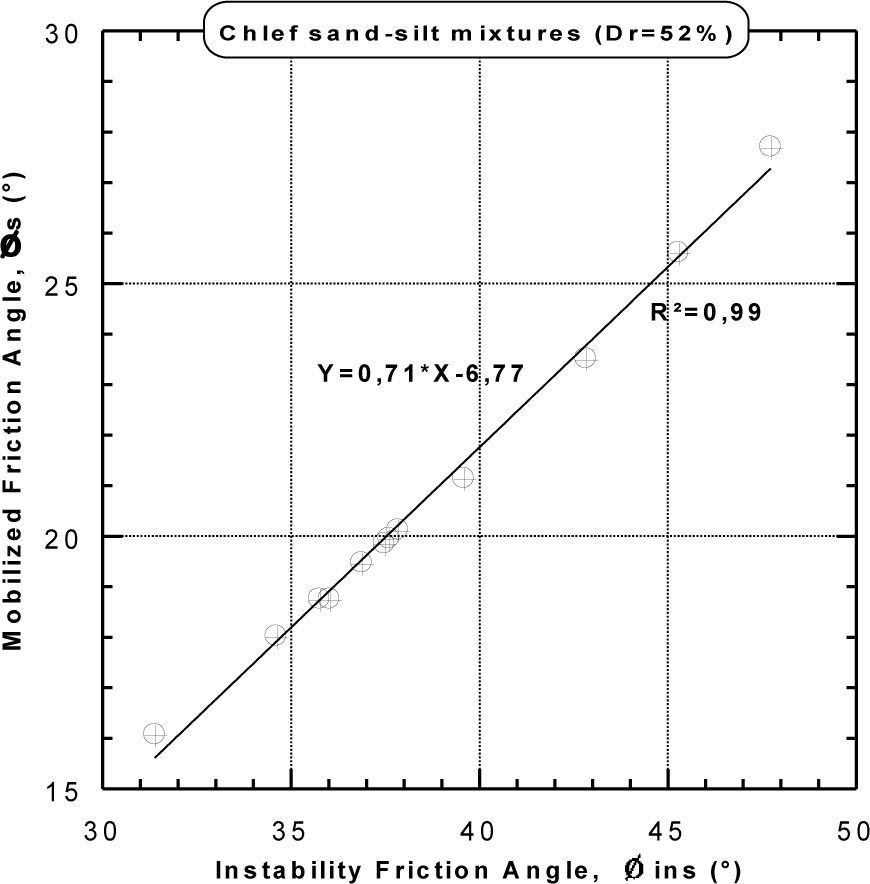
Figure 23
Mobilised friction angles versus instability friction angle of Chlef sand–silt mixtures.
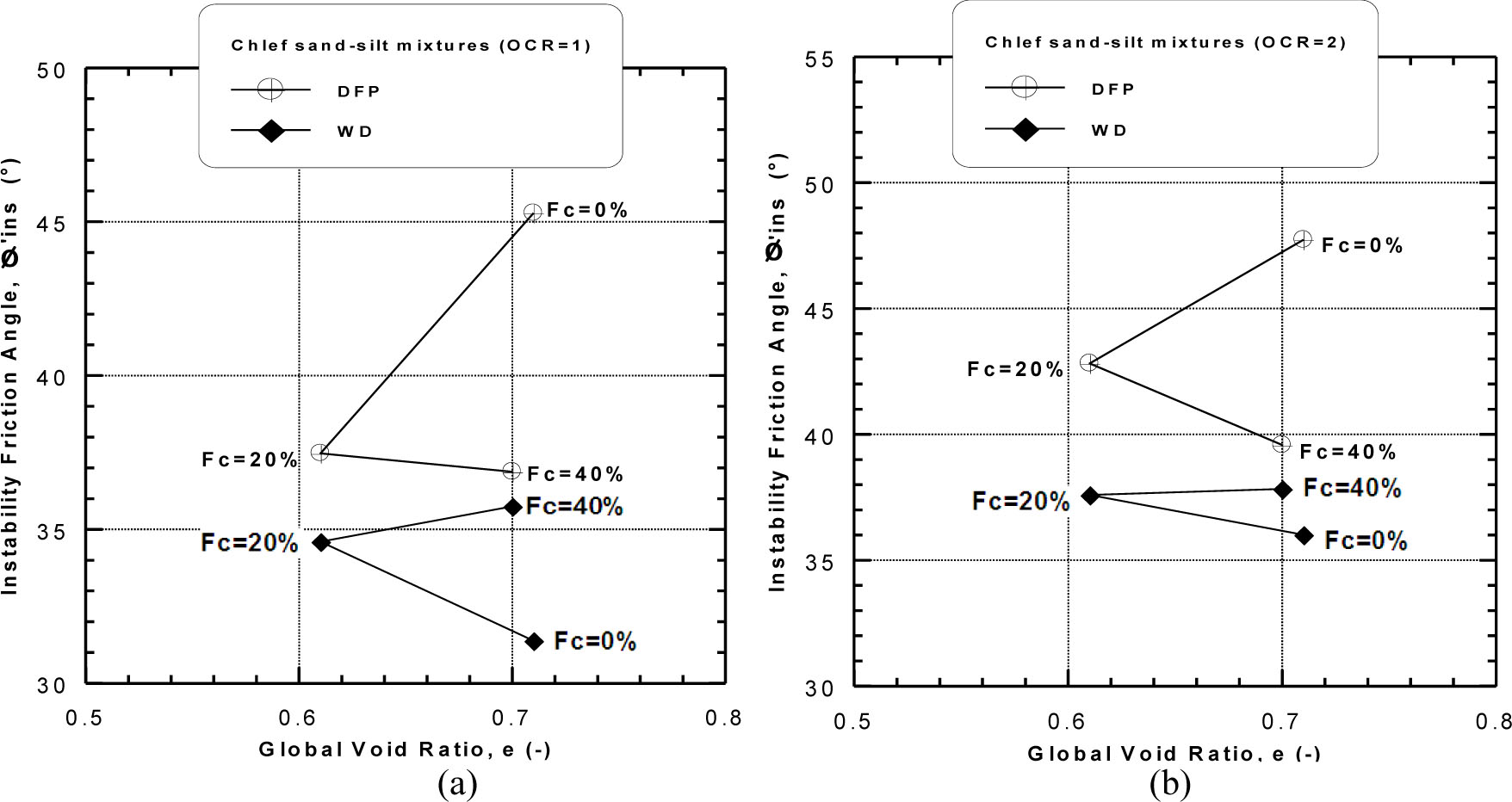
Figure 24
Instability friction angles versus global void ratio: (a) OCR = 1 and (b) OCR = 2.
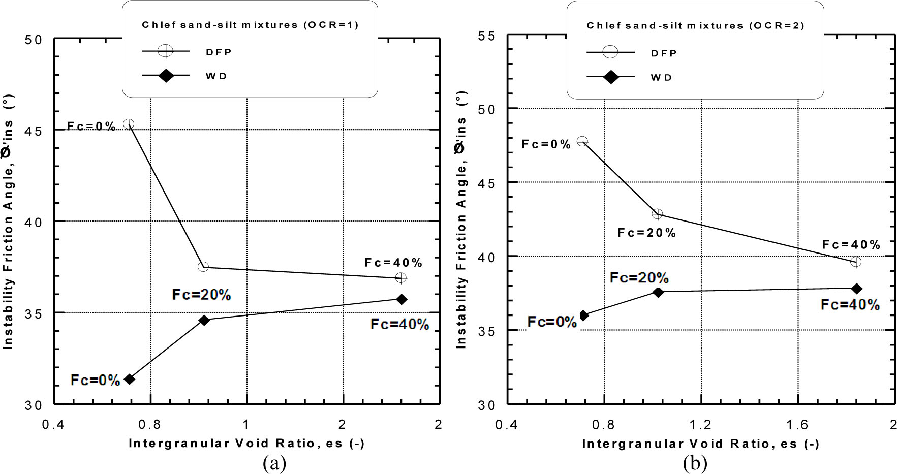
Figure 25
Instability friction angles versus intergranular void ratio: (a) OCR = 1 and (b) OCR = 2.