
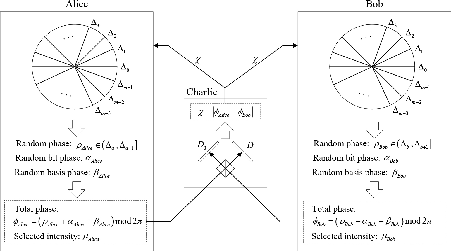
Figure 1.
The basic structure of TF-QKD.

Figure 2.
Butterfly network model for twin-field transmission.
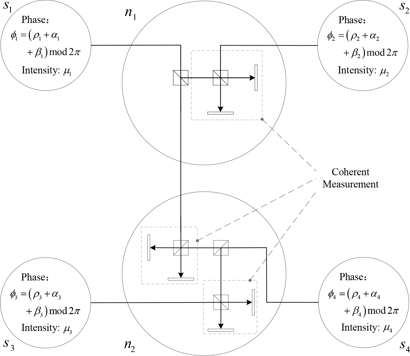
Figure 3.
Quantum operations at each node in the butterfly network.
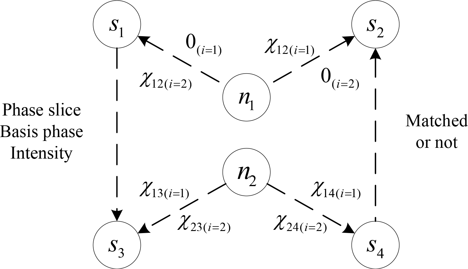
Figure 4.
Classical transmission after the coherent measurements.
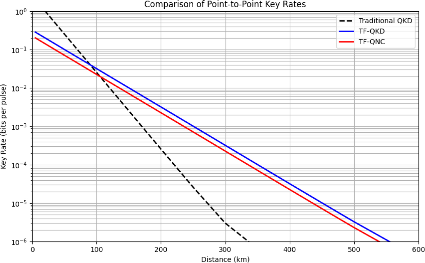
Figure 5.
Comparison of point-to-point key rates.
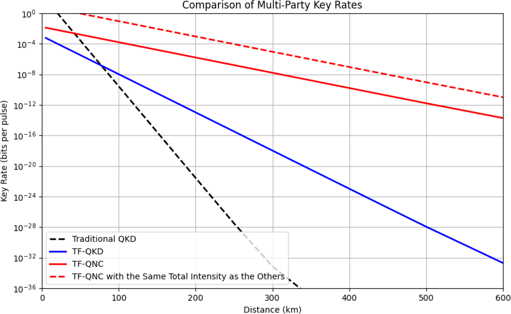
Figure 6.
Comparison of multi-party key rates.
Table 1.
Comparison of channel usage between TF-QNC and TF-QKD.
Table 2.
Comparison of quantum states usage between TF-QNC and TF-QKD.
| Scheme | Quantum states in one execution | Average total number |
|---|---|---|
| Point-to-Point TF-QKD | 2 nodes × 1 | 2n1 |
| Point-to-Point TF-QNC | 2 nodes × 1 | |
| Multi-Party TF-QKD | 4 nodes ×3 | 12n2 |
| Multi-Party TF-QNC | 4 nodes × 1 | 4γn2 |
Table 3.
Comparison with other QNC schemes.
| QNC scheme | Quantum resources | Possibility to be used in QKD | Relationship between key rate and transmittance |
|---|---|---|---|
| XQQ [2] | Non-orthogonal quantum states | No | - |
| QNC based on PE scheme [3,6,12] | Pre-shared entanglements | Possible | R ∝ η |
| QNC with repeaters [11] | Quantum repeaters | Possible | R ∝ η1/n |
| QNC based on MBQC [5,9] | Cluster states | No | - |
| Our scheme | Weak coherent states | Yes | R ∝ η1/2 |