
Based on the fundamental principles of quantum physics, quantum communication has achieved a revolutionary breakthrough compared to classical communication. Currently, quantum communication has developed from point- to-point transmission to network architecture. In both quantum and classical networks, bottleneck channels often severely restrict communication efficiency. In 2000, Ahlswede and Cai [1] introduced the concept of classical network coding. It allows data encoding at intermediate nodes to maximize the network throughput through bottlenecks. To solve analogous problems in quantum networks, Hayashi [2] introduced the first quantum network coding (QNC) scheme, XQQ, in 2007. It utilized universal cloning and local unitary operations to simulate the replication and encoding operations of classical network coding. Later, the scheme was further enhanced by incorporating pre-shared entanglement (PE) [3], enabling perfect cross-transmission of two quantum states through a bottleneck channel. Subsequent researches were inspired and started to focus on perfect multi-unicasts. In 2014, Shang et al. [4] proposed a QNC scheme based on controlled teleportation, introducing a controller to manage the decoding process. In 2016, Li et al. [5] utilized 2D and 3D cluster states to achieve quantum multi-unicast over directed acyclic networks. In 2023, Shang et al. [6] proposed a QNC scheme based on quantum steering, relaxing the constraints on quantum entanglement and the security assumptions for intermediate nodes. Same as the classical network coding, QNC is also expected to achieve multicast. The no-cloning theorem prohibits the perfect replication of unknown quantum states, making it impossible to achieve perfect multicast in quantum networks. The first QNC to realize strict multicast was proposed by Shi et al. [7] in 2006. It sends existing clones of a state without cloning it during the transmission. In 2022, Hirota et al. [8] reformulated quantum multicast as an approximation cloning problem and designed a QNC scheme to multicast asymmetric optimal clones of an unknown quantum state. In 2023, Pandey et al. [9] proposed a QNC scheme based on measurement-based quantum computing (MBQC) and addressed the challenges of both multi-unicast and strict multicast across different computational bases. In 2024, Yang et al. [10] introduced quantum multiplexing into QNC, making it possible for several source nodes to send states with different qubit numbers at the same time.
Current QNC schemes are still confronted with some challenges. Quantum states are highly susceptible to environmental factors. It has emerged as a critical issue to extend the communication distance. Quantum repeaters are commonly used in QNC to overcome the limit of distance. In 2015, Shang et al. [11] designed a QNC scheme based on quantum repeaters, employing local operations and classical communication (LOCC) algorithms for arbitrary entangled states to generate long-distance quantum channels. In 2020, Liu et al. [12] proposed a QNC scheme with the entanglement distribution of separable states and remote state preparation, enabling long-distance cross-transmission of quantum states on a butterfly network with reduced resources. In 2021, Shang et al. [13] transmitted quantum correlations rather than states over a butterfly network. This approach minimized decoherence effects on state selection and improved the communication distance of QNC. In quantum key distribution (QKD), twin-field (TF) structure [14] was designed for long-distance communication. The key rate of TF-QKD scales with the square root of the channel transmittance. If QNC can be combined with TF-QKD, it is possible to realize long-distance multi-party key distribution.
As the most developed quantum technology to date, QKD has been widely implemented. QKD protocols allow legitimate parties to obtain quantum keys with unconditional security in the presence of illegal eavesdroppers. Since the first QKD protocol BB84 was introduced by Bennett and Brassard [15]. In 1984, QKD has undergone various developments and become one of the most widely adopted quantum communication technologies with unparalleled technological maturity. In 1991, Ekert [16] proposed the E91 protocol based on entanglement distribution, which ensures the security of QKD by verifying the violation of Bell’s inequality. As QKD protocols have been increasingly deployed, studies have started to focus more on security. In practical QKD systems, it is impossible to maintain ideal environment and device conditions. For instance, non-ideal light sources make the system vulnerable to photon number splitting (PNS) attacks, where eavesdroppers exploit multi-photon emissions to gain information about the key. Non-ideal detectors at the receiver end may also lead to side-channel attacks such as time-shift, Trojan-horse, fake-state, and avalanche-transition attacks [17–19]. Hwang [20] first proposed the concept of decoy states as a countermeasure against PNS attacks. Decoy-state (DS) techniques have since evolved rapidly and have been integrated into a wide range of QKD systems [21,22]. In 2010, Gisin et al. [23] proposed the device-independent (DI) QKD, which enables secure communication over an untrusted network with untrusted devices. Then, Laing et al. [24] introduced the reference-frame-independent (RFI) QKD, mitigating the problem of reference frame misalignment. In 2012, Lo et al. [25] further proposed the measurement device-independent (MDI) QKD. It involves two senders and one untrusted receiver, providing robust resistance against side-channel attacks targeting measurement devices. In systems with detector losses and other experimental imperfections, none of the aforementioned QKD protocols can surpass the secret-key capacity (SKC) bound, the theoretical maximum amount of secret information that can be transmitted through QKD. To overcome this limitation, Lucamarini et al. [14] introduced TF-QKD based on MDI-QKD in 2018. In TF-QKD, two distant nodes independently generate phase-randomized states and subsequently transmit them to an intermediate node for interference. Moreover, TF-QKD can be directly implemented on the existing hardware of MDI-QKD, so it inherently retains the measurement-device-independent security. There are numerous variants of TF-QKD designed for different scenarios. Notable examples include the sending-or-not-sending (SNS) and the phase-matching (PM) protocol [26,27], advancing the practicality and scalability of TF-QKD. The twin-field structure and the coherent measurement at the intermediate node are applied in TF-QKD to improve communication distance, which also reveals a viable pathway to overcome the distance limitation in QNC. QNC typically requires end-to-end transmission of quantum states, making it impossible to surpass the SKC bound even with the assistance of repeaters. If the twin-field structure and coherent measurements were introduced, QNC will be able to support long-distance multi-party interactions in the networks with bottlenecks.
In this paper, we propose a twin-field quantum network coding scheme. The transmission directions in the butterfly network model are changed and coherent measurements are introduced to intermediate nodes, enabling simultaneous quantum key distributions for multiple node pairs with only one transmission round through the bottleneck. Considering the security threats from malicious intermediate nodes, we also derive various decoy-state transmission features for this scheme so that all parties are able to determine whether eavesdroppers or malicious nodes exist. The main contributions of this paper are summarized as follows:
- (i)
A butterfly network model with centripetal transmission directions on both sides of the bottleneck is designed to support long-distance communication. All four end nodes are designated as senders, transmitting states to the intermediate nodes. Quantum transmission does not need to traverse the entire end-to-end channel, so the communication distance can be increased with a proper coding scheme.
- (ii)
A twin-field quantum network coding (TF-QNC) scheme for multi-party key distribution is proposed. Beam splitters and coherent measurement operations are implemented at the two intermediate nodes, allowing all communication parties to derive key bits based on the measurement results. The intermediate nodes have only access to the phase difference instead of the absolute phase, so they are incapable of deducing the key bits if they are malicious.
- (iii)
The key rate and decoy-state transmission features in TF-QNC are derived to demonstrate the performance and security of the scheme. The decoy-state method suggests that eavesdroppers can be detected with a comparison between the actual features and their theoretical values. In the proposed scheme, quantum transmission involves more than one node, and untrusted intermediate nodes act as both signal receivers and measurement units, so the implementation of the decoy-state method is non-trivial.
TF-QKD [14] was designed based on MDI-QKD to overcome the communication distance limitations of traditional QKD. The phase difference of two signals is obtained at the intermediate node through coherent measurement, so that two remote nodes can deduce key bits without end-to-end transmission of quantum states.
The basic structure of TF-QKD is depicted in Figure 1. Alice and Bob are the legitimate, end nodes, and Charlie is an untrusted intermediate node. Prior to the transmission, Alice and Bob first agree to divide the phase interval [0,2 π) into m equally spaced slices. Then, they each select a random phase, respectively, and note down which slice (Δa, Δa+1] or (Δb, Δb+1] the phase is in, where a, b ∈ ℤ ⋂ [0, m) and Δm = Δ0. To deliver information and confuse eavesdroppers, they also have to choose random bit phases αAlice, αBob and basis phases βAlice, βBob. Finally, Alice prepares a state with phase ϕAlice = (ρAlice + αAlice + βAlice) mod 2π and selected intensity μAlice, while Bob prepares a state with phase ϕBob = (ρBob + αBob + βBob) mod 2π and selected intensity μBob and sends them both to Charlie. Charlie uses two detectors D0 and D1 to measure the phase difference χ between ϕAlice and ϕBob and publish it. The difference is 0 or π. Alice now reveals the intensity μAlice, basis phase βAlice and slice (Δa, Δa + 1]. According to these data, Bob can determine whether the states match or not. After all rounds are completed, Bob announces the matching rounds and discards the non-matching ones. For the matching rounds, they disclose the bits corresponding to non-signal states, which are then used to detect eavesdropping. To generate key bits, Bob deduces Alice’s bit phase of every signal state as αAlice = |χ – αBop|. The bit corresponding to αAlice will serve as the shared key bit.
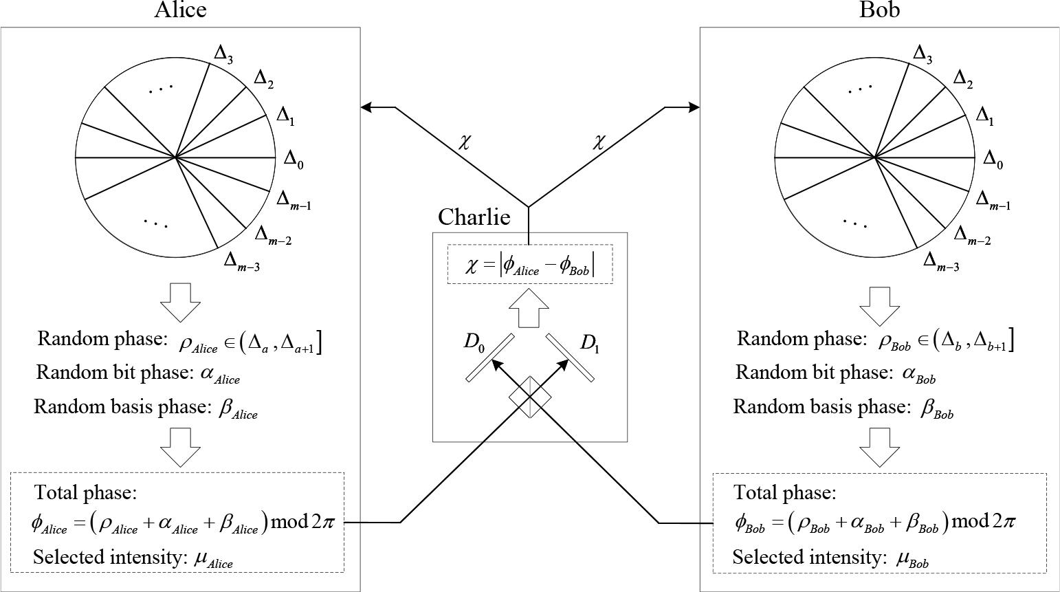
The basic structure of TF-QKD.
According to the analysis of TF-QKD, the key rate can be expressed as
In practical implementations, weak coherent state sources are often employed instead of ideal single-photon sources, which means it is possible to have more than one photon in one pulse. This vulnerability can be exploited by an eavesdropper through a PNS attack. They extract information on key bits by intercepting photons from multiphoton pulses. In the decoy-state method, eavesdropping is detected by the estimation and verification of the decoystate transmission features. The features must be sensitive to photon numbers, such as the transmission gain Q and error rate E.
We assume that the sender emits a weak coherent state
After transmission, the actual values of Qμ and Eμ are observed. If they obviously deviate from the theoretical predictions, the transmission is highly likely to be eavesdropped.
Inspired by the coherent measurement introduced to the intermediate node in TF-QKD to improve communication distance, we design a twin-field quantum network coding scheme to distribute keys for multiple parties through a bottleneck channel. Based on a new butterfly network model with reconfigured transmission directions, we enable intermediate nodes to perform coherent measurement, beam splitting, and coding operations, thereby allowing a single quantum transmission in the bottleneck channel to carry more information.
Firstly, we describe a novel butterfly network model for twin-field transmission scenario. To provide a clear and structured explanation, we divide the proposed scheme into two stages. Then, we introduce the quantum transmission process and the coherent measurement operations performed by the intermediate nodes. Finally, we introduce the coding and classical transmission process after the measurement results are obtained at the intermediate nodes.
The proposed scheme is based on a butterfly network model depicted in Figure 2. Solid lines denote quantum channels. The bottleneck channel is capable of transmitting one quantum state at a time, and the others are capable of transmitting either one quantum state or one classical bit. Dashed lines denote classical channels. The nodes s1 to s4 are the communication parties and are mutually trusted. The nodes n1 and n2 are untrusted intermediate nodes. The four communication nodes are distributed over long distance. The distance between node group A and B is even longer than the distance inside each group. To alleviate the pressure of long-distance communication and optimize the use of channel resources, we assume that the classical channels s1s3 and s2s4 between the two node groups can only be used once, while free classical transmission is allowed within each group.
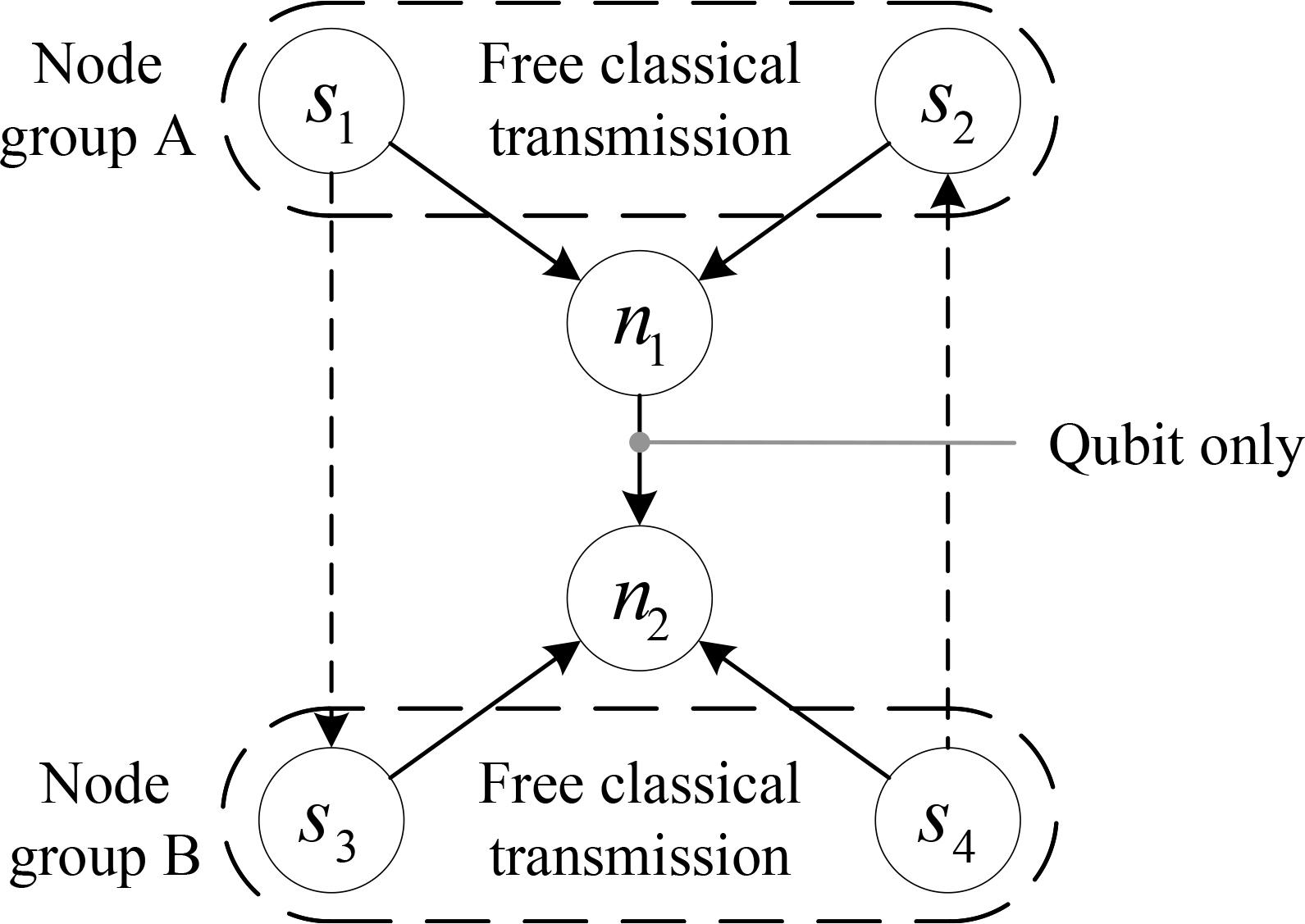
Butterfly network model for twin-field transmission.
We assume that the end nodes s1 to s4 expect to securely distribute keys among themselves. The keys between one pair of nodes can be identical or distinct to each other. Considering the distances between the nodes, the distribution of secure keys necessitates the use of TF-QKD. To extend TF-QKD to support long-distance multi-party communication in the new network model, the transmission directions of the traditional butterfly network model are changed, as illustrated by the arrows in Figure 2. The end nodes s1 to s4 all serve as the senders of quantum states, and the intermediate nodes n1 and n2 serve as the receivers. The current circumstances on both sides of the bottleneck channel are completely symmetric, so we reasonably assume that the quantum transmission in the bottleneck channel is directed from n1 to n2. In TF-QKD, classical transmission between source nodes is needed to determine the rounds that match, so at least two interactions, one in each direction, are necessary between the two node groups. For simplicity, we further assume that the classical transmission is directed from s1 to s3 and from s4 to s2.
Compared to butterfly network models in other schemes, the transmission directions in the proposed model are changed to support longer communication distances. Quantum states are transmitted from the end nodes to the intermediate nodes. Additionally, the bottleneck in the model is a quantum channel, which is more common in current quantum systems. The side channels are only used to transmit auxiliary classical information in round selection.
The TF-QKD protocol is designed to achieve point-to-point key distribution. If we aim to enable communication between any two of the four nodes, we need to distribute C (4,2) = 6 pair of keys, where C (n, k) denotes the binomial coefficient. Four pairs of keys must be transmitted through the bottleneck quantum channel, which is impossible for a single round of quantum transmission without coding. Therefore, we will introduce the transmission and coding procedures of the TF-QNC scheme.
Our TF-QNC scheme contains two stages in sequence. In the quantum transmission stage, the end nodes in the network transmit phase-randomized quantum states to the intermediate nodes. The intermediate nodes then perform coherent measurements on the states. In the classical transmission stage, the intermediate nodes calculate the phase differences between the states and send them to the end nodes in the form of classical bits. Based on the locally prepared states and the phase differences, the end nodes can derive the group key.
In systems with insecure channels, single-photon signals can perfectly prevent eavesdropping. Due to the imperfections of light sources, attenuated weak coherent states are commonly used in practical implementations as a substitute for ideal single-photon signals. This makes PNS attacks possible, since a certain proportion of the signals contain more than one photon. Current decoy-state methods can effectively prevent PNS attacks in systems with imperfect light sources. Thus, it will not undermine the security of the transmission to deliver information with the redundant photons in the unavoidable multi-photon signals.
Replication and coding are the two fundamental operations in classical network coding, which are usually simulated in QNC using approximate cloning and unitary transformations. In the proposed scheme, we simulate replication by employing beam splitters to split multi-photon signals and simulate linear coding by employing coherent measurements to obtain phase differences at each intermediate node. The quantum transmission stage based on the proposed network model is illustrated in Figure 3. In this stage, quantum transmission is achieved via the quantum channels in the model. Each channel is used only once, carrying one single quantum state per transmission.
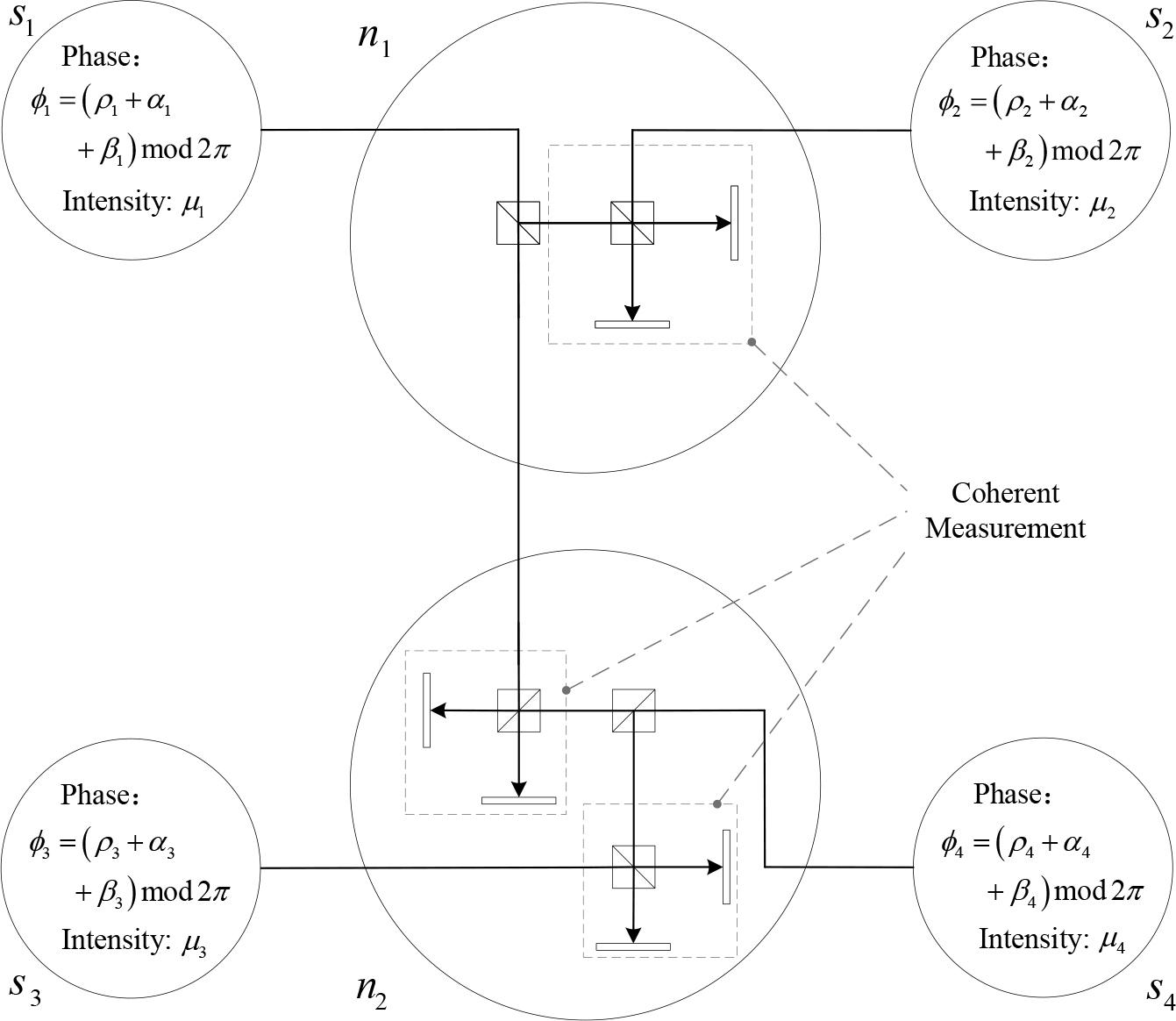
Quantum operations at each node in the butterfly network.
The detailed process of the quantum transmission stage is described as follows. In this process, Steps 1 and 2 are performed only once before the first round of transmission begins, while all other steps are repeated in every round thereafter.
Similar to the initialization in TF-QKD, the four end nodes s1 to s4 agree to divide the phase interval [0,2 π) into m equally spaced slices (Δk, Δk + 1] before all transmission rounds begin, where k ∈ ℤ ⋂ [0, m) and Δm = Δ0. Furthermore, for each quantum channel in the butterfly network model, the sender of the signal needs to transmit an unmodulated high-intensity pulse to the receiver to enable precise channel calibration.
According to the decoy-state method, each end node can send three types of states: signal, decoy, and vacuum. Although the decoy-state method theoretically requires an infinite number of decoy states with different intensities to guarantee the detection of eavesdropping, it has been proven that only a limited number of decoy states are enough to achieve approximate performance [28]. In real-world implementations, two decoy states are able to meet the security requirements for most scenarios. Assuming that the current transmission plans to use two decoy states, the end node si, i ∈ ℤ ⋂ [1,4] needs to select the intensity μi ∈ {μ, v, w, 0} based on the type of state to be sent, where μ corresponds to signal states, v and w correspond to different decoy states, respectively.
Each end node si needs to determine the phase of the state to be sent. The phase of each state consists of three components. Firstly, si randomly selects a bit phase αi ∈ {0, π}, where 0 and π correspond to the key bits 0 and 1. Secondly, it randomly selects a basis phase βi ∈ {0, π/2}, where 0 and π/2 correspond to the measurement bases X and Y, respectively. Finally, to realize phase randomization, it randomly selects another phase ρi ∈ [0,2 π) and notes down which phase slice (Δki, Δki + 1] the phase ρi is in, where ki ∈ ℤ ⋂ [0, m).
Each end node si prepares a signal Si with phase ϕi = (αi + βi + ρi) mod 2π and intensity μi.
The nodes s1 and s2 send signals S1 and S2 to n1. The nodes s3 and s4 send signals S3 and S4 to n2.
At n1, beam splitting on one of the received signals should be performed first. Given that the signals are attenuated and have an average photon number of 1, only a minor portion of them contain more than one photon. To improve the success rate of the measurement and forwarding operation, we do not predetermine the signal to be split. The process proceeds as long as at least one of the signals contains more than one photon. Initially, a photon number resolving detector (PNRD) [29] is used to ascertain the photon numbers of signals S1 and S2. If S1 contains more than one photon, the beam splitting is performed on S1. If S1 contains only one photon and S2 contains more than one photon, the beam splitting is performed on S2. Otherwise, the current round is discarded. Without loss of generality, we assume that S1 is the signal to be split. The intermediate node n1 performs the beam splitting on S1 and gets S11 and S12. Then, it forwards S11 to n2 and performs a coherent measurement on S12 and s2. The coherent measurement here is identical to the measurement performed in the original TF-QKD [14]. It is implemented by interfering the two incoming optical pulses on a 50:50 beam splitter and monitoring the outputs with a pair of single-photon detectors. A detection event in exactly one detector heralds a successful measurement and reveals the phase difference between the two input pulses. If both detectors click or neither clicks, the current round is discarded. If only one detector clicks, the phase difference χ12 = |ϕ1 – ϕ2| is obtained.
Similar to the process at n1, at n2, beam splitting should be performed first on one of the signals received from the source nodes s3 and S4. We assume that the signal S4 from s4 contains more than one photon. The node n2 performs beam splitting on s4 and gets S41 and S42. Then, it performs two coherent measurements, one on S11 (received from n1) and S41, the other on S42 and S3. In any of the two measurements, if both detectors click or neither clicks, the current round is discarded. If only one detector clicks in both measurements, the phase difference χ14 = |ϕ1 – ϕ4| between S11 and S41 is obtained as well as the phase difference ϕ34 = |φ3 – ϕ4| between S42 and S3.
In the quantum transmission stage, information is transmitted from source nodes to intermediate nodes. All the following transmissions will be accomplished via classical communication. The maximum distance for quantum transmission is two hops, which is shorter than the end-to-end distance, thereby extending the communication range of the quantum network. Meanwhile, since only one quantum state transmission is required in the bottleneck channel, the overall efficiency of the network is improved.
After the coherent measurement, the intermediate nodes n1 and n2 need to transmit the results via classical communication to the end nodes for key bit deduction. We consider two scenarios:
All four end nodes s1 to s4 expect to distribute a group key through the butterfly network with bottleneck.
Two pairs of end nodes expect to distribute distinct keys simultaneously. For example, s2 and s3 want to share a key different from the key shared by s1 and s4.
In the first scenario, if only the point-to-point TF-QKD protocol is used to cover the distance, the keys distributed between every pair of nodes are different due to the randomness of information encoded in each quantum state. To enable communication among the nodes s1 to s4, a key must be distributed between each two nodes, which requires the protocol to be executed C(4, 2) = 6 times. Consequently, the bottleneck channel must be used at least 4 times, and each of the other quantum channels must be used at least twice.
In the second scenario, if only the point-to-point TF-QKD protocol is used to cover the distance, the interaction between s2 and s3 requires transmission in the bottleneck channel as well as the interaction between s1 and s4. Two different quantum states need to traverse the same channel, so the channel must be used at least twice.
Without any coding scheme, both scenarios require more than one round of quantum transmission. Channel resources are not fully utilized, thereby constraining the efficiency of the network. The goal is to achieve key distribution with only one round of quantum transmission by coding the coherent measurement results. The quantum transmissions for both scenarios are identical. The classical transmission process is shown in Figure 4. In the quantum stage, the choice of the forwarded signal has no impact on the state transmission or measurement process. However, in the classical stage, if the forwarded signal is not specified, the end nodes will have trouble generating identical key bits. To optimize channel resource utilization, instead of using an additional round to identify the forwarded signal, we calculate the phase differences between the forwarded signal and the signal sent from each node. Consequently, all four end nodes can deduce the bit encoded in the forwarded signal as the shared key bit. For each round, the classical process for the first scenario is described as follows.
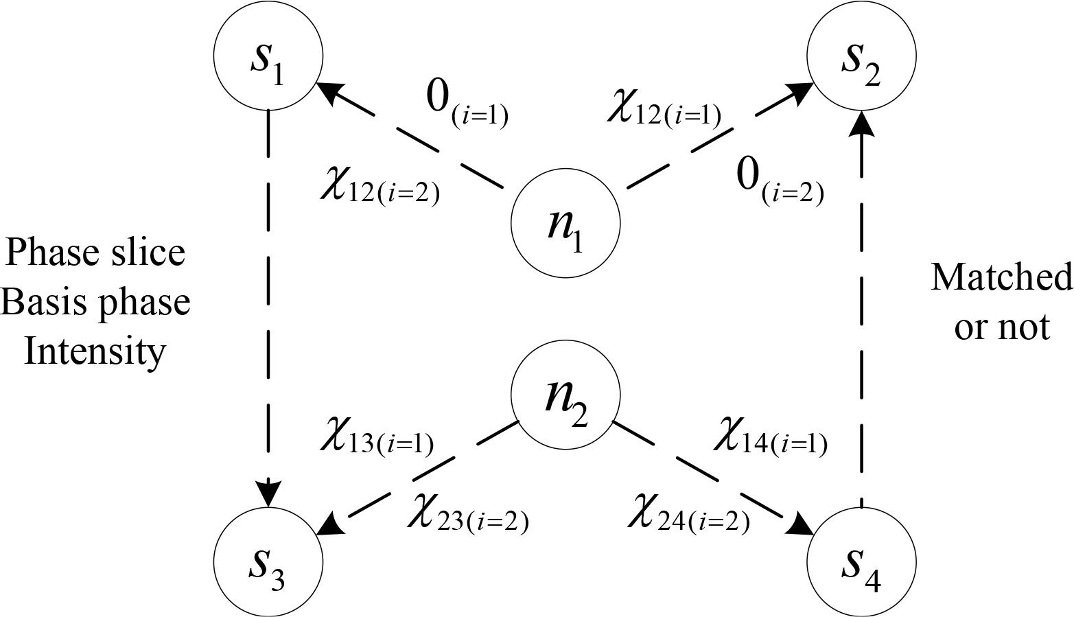
Classical transmission after the coherent measurements.
Let Si, i ∈ {1,2} denote the signal successfully split and forwarded at n1. The node n1 computes the phase differences χ1i and χ2i. When i = 1, i.e., S1 is the forwarded signal, χ1i and χ2i can be expressed as
Similarly and simultaneously, let Sj, j ∈ {3,4} denote the signal successfully split and forwarded at n2. The node n2 computes the phase differences χ3i = |ϕ3 – ϕi| and χ4i = |ϕ4 – ϕi|. Different from n1, n2 performs two coherent measurements after beam splitting to obtain phase differences χ34 and χij. The coherent measurement only detects two possible phase differences, 0 or π. Due to the binary nature of the phase difference measurement and the modulo 2π arithmetic, when j = 3, i.e., S3 is the forwarded signal, χ3i and χ4i can be expressed as
The node n1 sends one classical bit to each of s1 and s2, encoding χ1i and χ2i, respectively. The node n2 sends one classical bit to each of S3 and s4, encoding χ3i and χ4i, respectively. The binary values {0,1} of each classical bit map to the phase differences {0, π}, following the correspondence 0 → 0 and 1 → π.
In the proposed butterfly network model, classical information exchange is assumed to be unlimited between s1 and s2 as well as between s3 and s4. Any end node may initiate the round matching. Let s3 first disclose the modulation settings of its signal. For signal states, the settings include the phase slice, basis phase, and intensity. For decoy states, bit phase is also included for eavesdropping detection. The matching process can be further decomposed into four substeps:
Substep 1: The node s3 discloses its modulation settings to s4.
Substep 2: The node s4 verifies the consistency between the received settings and its own. If matched, s4 forwards the information to s2 via the long-distance channel. Otherwise, it notifies s2 and s3 to discard the round, and s2 then informs s1.
Substep 3: The node s2 verifies the consistency between the received settings and its own. If matched, s2 forwards the information to s1. Otherwise, it notifies s1 to discard the round. Then s1 informs s3 and s3 informs s4.
Substep 4: The node s1 will obtain the final matching result after its verification. It forwards the result to s3 via the long-distance channel and to s2. Then, s3 informs s4.
All end nodes ultimately determine the valid rounds for key generation. The two long-distance channels are used only once. This matching process and subsequent key generation steps can also be performed after all rounds have been completed, which introduces additional decoding latency and reduces the pressure on classical transmissions at the same time.
For the matched rounds, the end nodes need to decode the key bits based on local information. Before key generation, each node sn, n ∈ ℤ ⋂ [1,4] has access to its own bit phase αn and the phase difference χni relative to signal Si. According to the mapping rules in Step 3, if the classical bit corresponding to αn and χni is denoted as bn and bni, sn can deduce the classical bit bi corresponding to the bit phase if signal Si by
After the classical transmission stage, all end nodes obtain the same bi, which then serves as the key bit generated in the current round. After all rounds are completed, the final secret key is obtained by concatenating the bits generated in each round.
As for the second scenario, the coding and transmission of the phase differences remain the same. Before round matching, the two pairs of end nodes first negotiate to use states with different basis phases during key distribution. For example, s2 and s3 use the states with basis phase of 0, while s1 and s4 use the states with basis phase of π/2. During key generation, each node only decodes the states that match its own basis phase, which enables the two pairs of nodes to generate different keys. An external eavesdropper cannot infer one key from the other. If the two pairs are mutually untrusted, the latter node in a pair may choose to encrypt the matching result with the former node’s public key during round matching.
It should be noted that in early QKD protocols such as BB84 [15], basis phases are used to distinguish signal states from decoy states rather than carrying key-related information. In advanced protocols such as the original TF-QKD [14], signal and decoy states can be differentiated by light intensity so that basis phases can carry other information.
TF-QNC is designed to distribute long-distance multi-party quantum keys and improve network efficiency. Since QNC and TF-QKD are combined in the proposed scheme, two properties can be obtained as follows:
- (i)
TF-QNC extends the point-to-point QKD process to multi-party scenarios by introducing additional coding operations at intermediate nodes.
- (ii)
TF-QNC exhibits advantages in communication distance compared to schemes requiring end-to-end quantum transmissions.
TF-QNC is more efficient in the distribution of a group key than point-to-point TF-QKD protocols in multi-party scenarios. We first analyze the scenario where the four distant end nodes in the butterfly network expect to distribute quantum keys to enable communication between any two of them. TF-QNC takes only one quantum transmission round to distribute a group key among the end nodes, as demonstrated in Proposition 1.
If the nodes si, i ∈ ℤ ⋂ [1,4] in the butterfly network expect to enable communication between any two of them, TF-QNC reduces the number of required transmission rounds to 20% of the original.
When the original point-to-point protocol is used to distribute keys among end nodes, pairwise keys must be distributed, so the protocol must be executed C(4,2) = 6 times. Since states are randomized in the protocol, one node cannot distribute keys to multiple nodes in one transmission. To minimize the total number of rounds, we take simultaneous transmissions across different quantum channels into account. The detailed process is described as follows.
Step 1. The nodes s1 and s2 send their states to the intermediate node n1. Then n1 measures the phase difference between the two states and sends the results to s1 and s2. Meanwhile, the nodes s3 and s4 send their states to the intermediate node n2. Then n2 measures the phase difference between the two states and sends the results to s3 and s4. The two protocols can be executed simultaneously.
Step 2. The node s1 sends a state to n1. The node s3 sends a state to n2 and n2 forwards it to n1. Then n1 measures the phase difference between the two states and sends the results to s1 and s3.
Step 3. The node s1 sends a state to n1. The node s4 sends a state to n2 and n2 forwards it to n1. Then n1 measures the phase difference between the two states and sends the results to s1 and s4.
Step 4. The node s2 sends a state to n1. The node s3 sends a state to n2 and n2 forwards it to n1. Then n1 measures the phase difference between the two states and sends the results to s2 and s3.
Step 5. The node s2 sends a state to n1. The node s4 sends a state to n2 and n2 forwards it to n1. Then n1 measures the phase difference between the two states and sends the results to s2 and s4.
In each step, one classical round and one quantum round are needed. Round matching can be completed in a single round during post-processing. Apart from the transmissions for round matching, the process requires five classical rounds and five quantum rounds in total.
In TF-QNC, a shared key bit is distributed among the end nodes with only one classical round and one quantum round.
During the quantum round, all four end nodes simultaneously prepare and transmit their quantum states to the intermediate nodes n1 and n2. The bottleneck channel is used only once to transmit a split signal from n1 to n2 or vice versa.
During the classical round, the intermediate nodes calculate the phase differences for each end node and then send them back through classical channels. Each end node will deduce the common key bit based on the classical information and the state they sent during the previous quantum round.
According to the descriptions above, our scheme requires only one execution to distribute the group key, which contains one quantum round and one subsequent classical round. In contrast, key distribution among the four nodes using point-to-point TF-QKD needs to be serialized owing to the existence of the bottleneck channel. Therefore, it takes 20% of the original transmission rounds for TF-QNC to generate keys when the end nodes in the butterfly network expect to enable communication between any two of them.
Now we analyze the scenario where two pairs of nodes expect to distribute different keys through the bottleneck channel. TF-QNC can achieve the goal with half the transmission rounds at minimum, as demonstrated in Proposition 2.
If the nodes s2 and s3 expect to distribute one key while s1 and s4 expect to distribute another, TF-QNC takes 50% transmission rounds of the original at minimum.
When the original point-to-point protocol is used to distribute keys, two keys need to be generated independently. The node s2 first sends a state to n1. Simultaneously, s3 sends a state to n2 and n2 forwards it to n1. Then, s1 sends a state to n1. Simultaneously, s4 sends a state to n2 and n2 forwards it to n1. Apart from the transmissions for round matching, the process requires two classical rounds and two quantum rounds in total.
In TF-QNC, only one classical round and one quantum round are needed to generate one key bit. If the two pairs of nodes eventually distribute keys with identical bits, the scenario becomes completely equivalent to the first one. Thus, only 50% of the rounds are needed at minimum. The more overlapping bits between the two keys, the less rounds required when using TF-QNC.
In both scenarios with multi-party interactions, TF-QNC effectively reduces the number of transmission rounds, thereby improving the efficiency of the network.
TF-QNC is designed to achieve multi-party key distribution over long distances. Additional beam splittings at intermediate nodes may reduce the proportion of photons available for coherent measurement, which degrades the key rate of the scheme. We expect to show that the proposed scheme still maintains a communication distance advantage over schemes requiring end-to-end quantum transmissions such as conventional QKDs, as demonstrated in Proposition 3.
Among the three paths in TF-QNC where twin-field coherent measurements are used to obtain phase differences, the theoretical key rate on the most distance-constrained path scales linearly with η1/2, where η denotes the channel transmittance.
According to the analysis of the original TF-QKD protocol [14], the key rate satisfies RTF–QKD ∝ η1/2 and the key rate of any other conventional QKD protocol satisfies RQKD ∝ η. The channel transmittance η can be expressed as the geometric mean of the transmittances of all sub-channels. Therefore, TF-QKD improved the key rate over long distance compared to conventional QKD. In the proposed scheme, a twin-field signal transmission mode is applied three times on distinct paths, each on distinct directions and channels. In the proposed model, the distance between nodes in the direction parallel to the bottleneck channel is much longer, so the path traversing the bottleneck channel becomes the most distance-constrained. Now we analyze the key rate on this path in detail.
We assume that the signals used for coherent measurement in the most distance-constrained path are S1 and S3. The analysis for other cases is similar. Let η1 denote the channel transmittance between s1 and n1, η2 denote the channel transmittance between n1 and n2, η3 denote the channel transmittance between s3 and n2. The average transmittance
In the proposed scheme, beam splitters are introduced to intermediate nodes. Let t1 denote the transmittance of the beam splitter at n1 and t2 denote the transmittance of the beam splitter at n2, so the channel transmittance between s1 and n1 becomes t1η1, the channel transmittance between s3 and n2 becomes t2η3. The key rate in the most distance-constrained path can be expressed as
According to the proof of Proposition 3, we also know that RTF–QNC = (t1t2)1/4 RTF–QKD. Although RTF–QNC < RTF–QKD as
QKD protocols typically attenuate optical signals to maximize the proportion of single-photon states in transmission, which serves as a countermeasure against PNS attacks. In decoy-state method, specific channel parameters will be analyzed to resist PNS attacks targeting multi-photon states. For QKD protocols with decoy-state method, an additional proportion of multi-photon states brings no substantial security risks. If the intensity of the signal can be increased, we can achieve the same key rate as in TF-QKD, which is demonstrated in Proposition 4.
Under the same channel parameters, if the original TF-QKD scheme achieves a key rate of R with intensity μ, TF-QNC achieves a key rate of R with intensity
In the most distance-constrained path, the signals undergo beam splittings with transmittances t1 and t2 at n1 and n2. The probability PTF–QNC of achieving the photon number n satisfies
Express μ′ with μ and we obtain
Therefore, TF-QNC achieves the same key rate as TF-QKD in the most distance-constrained path if μ is raised to μ′. This result confirms that the performance reduction introduced with additional operations such as beam splitters is not a permanent deficit. It can be dynamically compensated for by adjusting the source intensity. This makes our scheme highly adaptable. Equation (15) provides a direct method to determine the intensity μ′ required to achieve a desired key rate R over long distances.
In this section, we analyze the scheme from the aspects of performance, security, and resource consumption.
To demonstrate the overall performance of TF-QNC, we analyze the key rate in a complete transmission round, as formalized in Proposition 5.
Assuming that all non-bottleneck quantum channels have identical transmission parameters, the overall key rate in TF-QNC can be expressed as
Provided that all non-bottleneck quantum channels have identical transmission parameters, the actual states to be split at n1 and n2 do not affect the key rate derivation, so we assume S1 and S3 to be the signal to be split. We derive the key rate of TF-QNC from the key rate of TF-QKD. According to the proof of Proposition 3, the key rate of TF-QNC in the most distance-constrained path between S1 and S3 satisfies
Similarly, we can derive the key rates on the other two paths in TF-QNC. For the path between S1 and S2, the key rate satisfies
In TF-QNC, all the end nodes need to generate the group key simultaneously based on the phase difference information in each path, so the overall key rate of TF-QNC is
Then we obtain the expression of overall key rate in Proposition 5.
To illustrate the impact of beam splitting, we provide a numerical example based on Proposition 5. Assuming symmetric 50:50 beam splitters are used at both intermediate nodes and all non-bottleneck channels have identical parameters, we have t1 = t2 = 0.5, so Equation 19 can be simplified to
This result indicates that the overall key rate R′ of the TF-QNC scheme is reduced by half compared to the case without multicast. The reduction is a fundamental performance trade-off for enabling the multi-cast functionality. It can be seen that the reduction is a constant factor that is independent of the transmission distance, so it does not compromise the fundamental distance advantage of the twin-field structure. Comparing the performance of a multiparty scheme to that of a point-to-point scheme is a comparison of two distinct design choices with different objectives. In multi-party scenarios, the proposed scheme retains superiority over pairwise TF-QKD implementations.
To validate the theoretical derivations and intuitively demonstrate the performance advantages of the proposed scheme, we now present the results of numerical simulation. The simulation parameters were primarily chosen in accordance with the pioneering work on TF-QKD [14] and the specifications of typical contemporary QKD systems to ensure the comparability and practical relevance of our results.
In our simulation, we assume that each node sends one signal state, one decoy state, and one vacuum state in one transmission. The intensities are set to μ = 0.5 for the signal state, v = 0.1 for the decoy state, and ω = 0 for the vacuum state, respectively. The channel model is similar to the one used in [14] with detector efficiency ηd = 60% and dark count rate ϒ0 = 10−7. The error rate e0 caused by the dark count rate is set to 0.5. The inherent system error rate caused by optical misalignment can be calculated from visibility V as ed = (1 – V)/2, where V is set to a reasonable value as 99.65%. Based on the parameters in a standard optical fiber channel, the attenuation coefficient is set to α = 0.2 dB/km, and the error correction efficiency factor is set to f = 1.16.
The simulation results are displayed in Figure 5 and Figure 6. Figure 5 shows the key rate comparison in a point- to-point scenario. Since beam splitters are introduced to support strict multicast, the key rate of TF-QNC has been slightly affected compared to the original TF-QKD when considering only point-to-point transmission. However, as shown in Figure 5, the attenuation rate of the TF-QNC key rate still satisfies the relationship RTF–QNC ∝ η1/2, which remains significantly superior to that of traditional QKD. Such evidence indicates that on a point-to-point path, TF-QNC inherits all the distance advantages of TF-QKD, introducing only a minor constant-factor reduction due to the additional beam-splitting operations. Meanwhile, TF-QNC shows a much better performance than TF-QKD in multi-party scenarios.
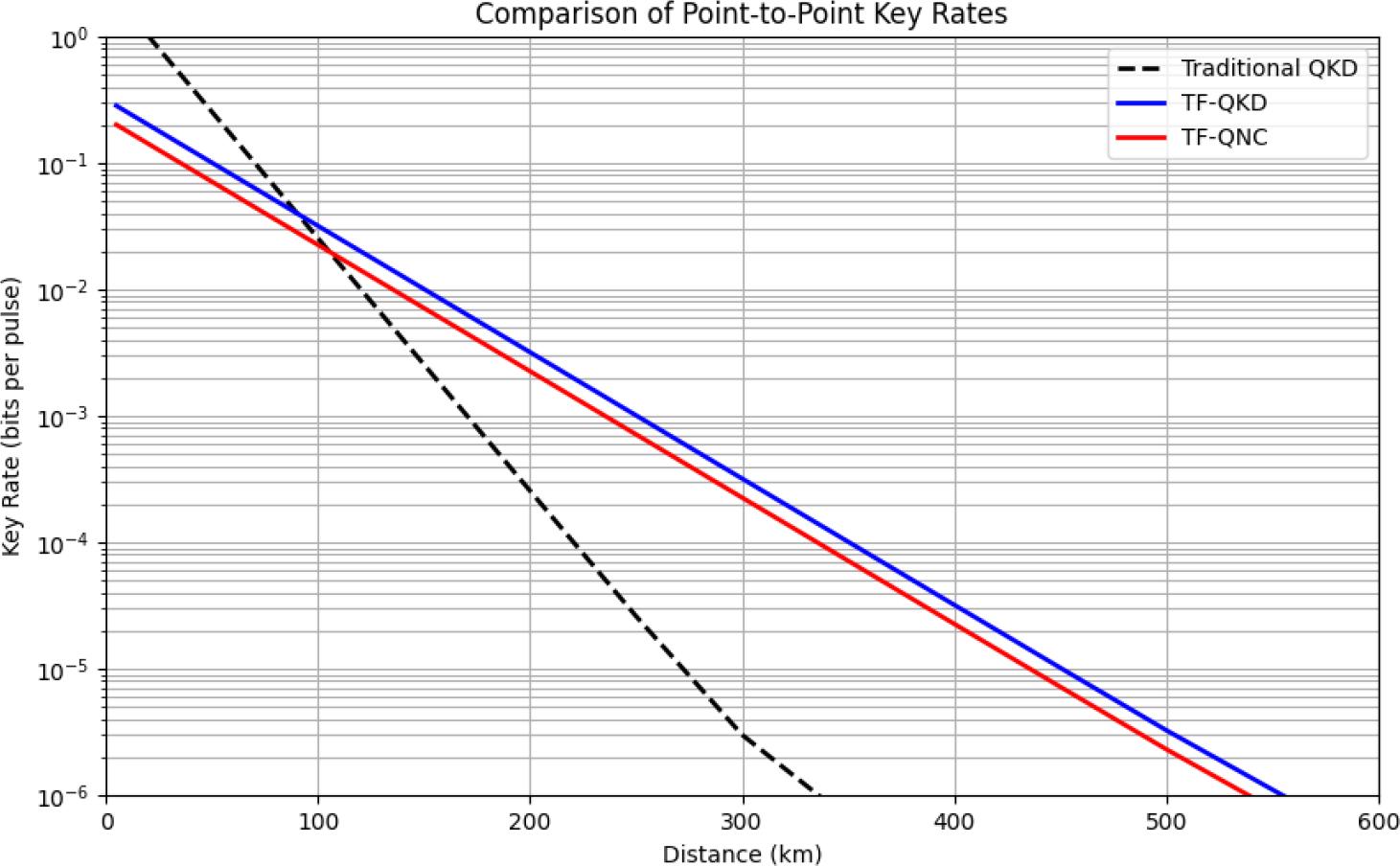
Comparison of point-to-point key rates.

Comparison of multi-party key rates.
Figure 6 shows the key rate comparison in a multi-party group key distribution scenario. TF-QKD undertakes a severe key rate reduction in this context, as it requires the sequential execution of the protocol multiple times for different user pairs. Our scheme accomplishes the distribution of a group key in a single execution, resulting in a much higher key rate. Furthermore, when we adjust the signal intensity of TF-QNC to μs = 1.5 to ensure a fair comparison under the same output power, its performance advantage becomes even more profound, particularly in the long-distance regime. Such evidence proves that TF-QNC is superior to the traditional method not only in terms of protocol efficiency but also in resource utilization efficiency.
The numerical simulation results provide strong support for our theoretical analysis. The TF-QNC protocol successfully extends the square root attenuation rate advantage of TF-QKD from the point-to-point scenario to the multi-party scenario. It effectively addresses the critical issue of bottleneck channels constraining multi-party efficiency in quantum networks without compromising security, offering a viable solution for constructing large-scale, long-distance quantum networks.
In the original TF-QKD, the intermediate node can only acquire the phase difference between the states instead of the absolute phase, so even if the intermediate node is malicious, it cannot deduce the secret key bits distributed by the protocol. The TF-QNC scheme is expected to retain the same security property under the condition of untrusted intermediate nodes, as demonstrated in Proposition 6.
In TF-QNC, malicious intermediate nodes n1 and n2 cannot deduce the phase of any states sent from the end nodes s1 to s4.
The functionality of n1 is divided into two parts: beam splitting and coherent measurement. A malicious n1 can be modeled as a combination of an eavesdropper capable of tuning the beam-splitting ratio and a malicious intermediate node in TF-QKD. Both threats also emerge in the original TF-QKD scenario and are already defended by the decoy-state method and the inherent twin-field structure.
Concretely, if n1 intercepts some photons originally designated for coherent measurement during beam splitting, the probability of successful phase difference acquisition at n1 will decrease. Similarly, if n1 intercepts some photons originally designated to be forwarded, the probability of successful phase difference acquisition at n2 will decrease. The total gain and the quantum bit error rate (QBER) will be affected in both cases. In the decoy-state method, these values will be compared with theoretical predictions and such malicious behaviors will be detected. From the perspective of an attacker, if n1 extracts no additional information during beam splitting, it will reduce to an intermediate node in the original TF-QKD, remaining incapable of deducing the absolute phase held by any end nodes.
The functionality of n2 is divided into three parts: one beam splitting and two coherent measurements. The situation of n2 intercepting photons by adjusting the beam-splitting ratio is the same as n1. Any malicious behavior will be detected by the decoy-state method. An advancement over n1 is that n2 can obtain the phase differences between any pair of the three states from the two coherent measurements. However, if no photon is intercepted, it is still impossible for n2 to deduce the absolute phase of any node.
If s1 to s4 expect to distribute a group key, the primary security threats come from eavesdroppers and untrusted intermediate nodes. If two pairs of nodes expect to distribute different keys, each pair must further guarantee that the other pair cannot deduce their key, as demonstrated in Proposition 7.
If s1 and s4 expect to distribute a key ka using the rounds in set ℛa while s2 and s3 expect to distribute a different key kb using the rounds in ℛb, s2 and s3 cannot deduce ka based on their knowledge of kb and the classical information exchanged during the interactions when ℛa ⊈ ℛb.
There are two main mechanisms in our scheme to prevent inter-group information leakage:
- (i)
Basis mismatch.
The two node pairs negotiate to use different bases for state preparation. During key generation, each node only processes the phase difference information that matches their own pre-negotiated basis. Consequently, the key ka derived by s1 and s4 appears random to s2 and s3 due to the basis mismatch, which effectively prevents s2 and s3 from deducing ka based on the key kb they derived themselves.
- (ii)
Blinded round matching.
The critical mechanism against leakage lies in the classical round matching process. In our scheme, all the end nodes need to participate in each round of quantum transmission. If s2 and s3 are both attackers, they may deduce information toward ka based on the classical feedback from the intermediate nodes at the end of each round. Therefore, we use the blinded round matching mechanism to hide the round matching results from different node pairs.
Since ℛa ⊈ ℛb, there exists at least one round r where r ∈ ℛa and r ∉ ℛb. In round r, s2 and s3 may use the wrong basis or intensity settings for the states intended for ka. During the round matching process, the matching results need to traverse all nodes. Assuming s4 is the latter node in the pair, it will encrypt the matching result with the public key of s1 before forwarding it to the next node whether the current round matches or not.
When s2 or s3 receives the encrypted message, it cannot decrypt it without the private key of s1. Therefore, they cannot determine whether their settings for round r is correct for generating ka or not and are forced to discard round r as invalid. After all rounds are completed, s2 and s3 lack the information for all the rounds like r. The final key ka is the concatenation of bits from all rounds in ℛa. Missing even a single bit makes deducing the complete key ka information-theoretically impossible.
Therefore, the two pairs can securely generate their respective keys without leaking information to each other. The security can be further enhanced by minimizing the intersection ℛa ⋂ ℛb.
According to Proposition 7, the smaller the intersection between sets ℛa and ℛb, the less information s2 and s3 can get toward the key shared between s1 and s4. It implies that if the two node pairs are mutually untrusted, minimizing the number of common rounds enhances the security of the scheme.
In current decoy-state methods, photon-number-sensitive channel parameters such as the transmission gain and QBER are usually statistically analyzed and compared with theoretical predictions to determine whether PNS attacks exist. To further specify the implementation of the decoy-state method in the proposed scheme, we derive the theoretical transmission gain and QBER. In the decoy-state method, the gain for a coherent state with intensity is defined as the probability that a signal pulse leads to a detection event at the receiver after transmission through a quantum channel. This probability contains all possible causes of detection, including the desired single-photon and multi-photon events as well as the noise from dark counts. We first examine the transmission gain in TF-QNC, as formalized in Proposition 8.
Assuming that all non-bottleneck quantum channels have identical transmission parameters and both intermediate nodes use 50:50 beam splitters, the overall gain of decoy-state transmission in TF-QNC can be expressed as
The function Qd (L, t) is the point-to-point gain. In a channel of length L with attenuation coefficient α, detector efficiency ηd and dark count ϒ0, Qd (L, t) can be expressed as
A single transmission round in which all end nodes send states with intensity μd is considered. According to the decoy-state method, if the photon number follows a Poisson distribution and there is a beam splitter with transmittance t on the path, the gain Qd (L, t) can be expressed as
Where ϒn|L is the yield of an n-photon pulse. It is the conditional probability of a detection event at the receiver’s side given that the source emitted a pulse containing exactly n photons. It is assumed to follow a Poisson distribution, and the overall value is taken over this distribution in the calculation of the gain. Under the assumptions of the standard decoy-state method, the multi-photon contributions are negligible for a low-intensity pulse, i.e., μd << 1. Furthermore, the vacuum yield is dominated by the dark count rate, so we have ϒ0|L ≈ ϒ0. The single-photon yield approximates the channel transmittance, so we have ϒ1|L ≈ η(L). Therefore, the expression simplifies to
Given that μd << 1, we can approximate e−μd ≈ 1, leading to the form of
To obtain valid results in the coherent measurement at n1, one of the signals S1 and S2 must be split successfully. If S1 fail to be split, the beam splitting is performed on S2. Therefore, the gain at n1 can be expressed as
There is a similar process at n2, so the gain of it can be expressed as
Additionally, n2 also have to perform a coherent measurement on the other half of the split signal and the signal sent from n1. The gain can be expressed as
The overall decoy-state gain in TF-QNC is
When the ratio of each beam splitter is 50:50, t1 and t2 satisfy t1 = t2 = 1/2. After substitution, we obtain Equation (25) in Proposition 8.
The QBER in a channel is also a photon-number-sensitive parameter, so it is also used to detect eavesdropping in the decoy-state method. According to the decoy-state method, if the photon number follows a Poisson distribution and there is a beam splitter with transmittance t on the path, the QBER Ed (L, t) can be expressed as
Within the theoretical framework of the decoy-state method, which assumes predictable devices and a known channel model, an obvious statistical deviation between the observed values and the theoretical predictions of gain and QBER is one of the important indicators when detecting the potential presence of eavesdropping.
In this section, the channel consumption and quantum resource consumption of the TF-QNC scheme are discussed. If the additional beam splitting operations are not considered, the proposed scheme distributes multi-party keys with 20% of the transmission rounds at minimum, which shows an advantage in resource consumption. Additional beam splitting may reduce the key rate over point-to-point paths, necessitating more transmissions to generate one key bit successfully. We expect to show that, even when the key rate on each point-to-point path is reduced due to additional beam splitting, the proposed scheme still requires less resource to distribute keys among the four end nodes compared to point-to-point TF-QKD protocols.
In both TF-QNC and TF-QKD, round matching can be performed after all quantum states and phase differences have been transmitted. If the round matching process is not considered, the proposed scheme requires the same number of channels and particles as the original TF-QKD for a single transmission along a point-to-point path. Specifically, two channels between the end nodes and the intermediate node are each used twice to transmit one qubit and one classical bit, respectively. For the most distance-constrained path mentioned in Proposition 3, the proposed scheme requires one classical transmission less than TF-QKD since no classical transmission is required in the bottleneck channel.
For the process of distributing keys among the four end nodes, in the proposed scheme, four non-bottleneck channels are each used twice to transmit one qubit and one classical bit, respectively. Additionally, the bottleneck channel is used once to transmit one qubit. In TF-QKD, keys must be distributed between any two nodes. Each node must send states and receive phase differences in three paths, so four non-bottleneck channels are each used six times, three for qubits and three for classical bits. Additionally, each node must distribute keys with the two nodes on the other side of the bottleneck, so the bottleneck channel needs to be used four times.
If the impact of additional beam splitting operations is taken into consideration, we have already derived the overall key rate of TF-QNC in Equation (19). The overall key rate of using point-to-point TF-QKD protocols to enable multi-party communication can be expressed as
In the proposed butterfly network model, we assumed the bottleneck channel to be even longer than the others. To simplify the calculation, we assume Lb = 2Lp and the ratio of beam splitting is 50%. According to the inherent properties of TF-QKD, the key rate RTF–QKD = βη1/2, where β is a constant coefficient. The transmittance η = η0e−αL, where η0 is the initial transmittance, α is the attenuation coefficient, so there is
Then, the overall key rate of TF-QNC can be expressed as
Therefore,
Comparison of channel usage between TF-QNC and TF-QKD.
| Scheme | Non-bottleneck channels | Bottleneck channel | Average total times |
|---|---|---|---|
| Point-to-Point TF-QKD | 2 channels × 2 | 2 | 6n1 |
| Point-to-Point TF-QNC1 | 2 channels × 2 | 1 | |
| Multi-Party TF-QKD2 | 4 channels × 6 | 4 | 28n2 |
| Multi-Party TF-QNC | 4 channels × 2 | 1 | 9γn2 |
Point-to-Point TF-QNC stands for TF-QNC executed on the most distance-constrained path;
Multi-party TF-QKD stands for TF-QKD executed between any two nodes in multi-party scenarios.
Comparison of quantum states usage between TF-QNC and TF-QKD.
| Scheme | Quantum states in one execution | Average total number |
|---|---|---|
| Point-to-Point TF-QKD | 2 nodes × 1 | 2n1 |
| Point-to-Point TF-QNC | 2 nodes × 1 | |
| Multi-Party TF-QKD | 4 nodes ×3 | 12n2 |
| Multi-Party TF-QNC | 4 nodes × 1 | 4γn2 |
Based on the comparison in Table 1 and Table 2, the proposed scheme exhibits lower resource consumption compared to the direct application of TF-QKD in multi-party communication.
Beyond channel and state consumption, the resources needed by the coherent measurements at the intermediate nodes should also be considered. Each coherent measurement unit requires one 50:50 beam splitter and two singlephoton detectors. To achieve multi-party key distribution, three executions of the coherent measurement need to be done at the two intermediate nodes. This part of resource consumption is lower than that of the original TF-QKD since it needs to be executed at least C(4,2) = 6 times to complete the same task.
To better demonstrate the advantages of our work within the broader field of quantum network coding, we also provide a comparison between the proposed TF-QNC scheme and several representative QNC schemes. Since our scheme has fundamental differences from other QNC schemes in terms of goals and assumptions, we compare the required resources, the possibility to be used in QKD, and the achievable distance to demonstrate the unique advantages of our scheme. Since existing QNC schemes are not considered in the context of quantum key distribution, we consider a scheme possible to be used in quantum key distribution scenarios if it can deliver states with fidelity 1 during the transmission. The key characteristics of each QNC scheme are summarized in Table 3.
Comparison with other QNC schemes.
| QNC scheme | Quantum resources | Possibility to be used in QKD | Relationship between key rate and transmittance |
|---|---|---|---|
| XQQ [2] | Non-orthogonal quantum states | No | - |
| QNC based on PE scheme [3,6,12] | Pre-shared entanglements | Possible | R ∝ η |
| QNC with repeaters [11] | Quantum repeaters | Possible | R ∝ η1/n |
| QNC based on MBQC [5,9] | Cluster states | No | - |
| Our scheme | Weak coherent states | Yes | R ∝ η1/2 |
As listed in Table 3, our scheme achieves R ∝ η1/2 without relying on demanding quantum resources such as pre-shared entanglements or repeaters. The weak coherent states used in our scheme are a highly practical and widely deployed light source, which makes it a practical solution for long-distance multi-party quantum networks.
In this paper, we proposed a twin-field quantum network coding scheme for the purpose of distributing group keys in long-distance multi-party scenarios. In particular, we designed a butterfly network model for long-distance multi-party communication, and then designed the quantum and classical coding process to overcome the bottleneck problem. Through scheme analysis, we demonstrated the security and the advantages in terms of efficiency and resource consumption of the proposed scheme. Compared to directly applying the original point-to-point TF-QKD, the TF-QNC scheme can achieve multi-party key distribution with half of the transmission rounds, with the key rate RTF–QNC on each path and the channel transmittance η still satisfying RTF–QNC ∝ η1/2. TF-QNC provides a foundation for future research on transmission schemes in quantum networks with more nodes and longer communication distances, thereby improving the efficiency of large-scale quantum networks constrained by bottleneck channels.