
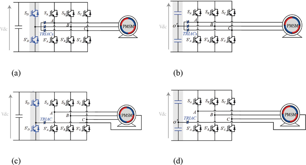
Figure 1.
Schematic of three-phase fault-tolerant topologies. (a) SFI. (b) CFI. (c) SFNI. (d) CFNI. CFI, capacitor-based four-leg inverter; CFNI, capacitor-based four-leg neutral-point-connected inverter; SFI, switched-based four-leg inverter; SFNI, switched-based four-leg neutral-point-connected inverter.
Table 1.
Comparative analysis of SFI, CFI, SFNI, and CFNI topologies.
| TRIAC | IGBT | Inverter side | Motor side | ||||||
|---|---|---|---|---|---|---|---|---|---|
| SFI (a) | Non | Non | 3 | 2 | 1.83 | 1 | 1 | √ | × |
| CFI (b) | Oui | Non | 3 | 0 | 1.5 | 0.5 | 1 | √ | × |
| SFNI (c) | Non | Oui | 1 | 2 | 1.86 | 0.58 | 0.58 | √ | √ |
| CFNI (d) | Oui | Oui | 1 | 0 | 1.28 | 0.5 | 0.58 | √ | √ |
Table 2.
Available voltage vectors with neutral point connected to the midpoint of the DC-link capacitor and phase a eliminated.
| Sb | Sc | uα | uβ | Vx | Amplitude |
|---|---|---|---|---|---|
| 0 | 0 | Vdc/3 | 0 | V1 | Vdc/3 |
| 0 | 1 | 0 | V4 | ||
| 1 | 0 | 0 | V2 | ||
| 1 | 1 | −Vdc/3 | 0 | V3 | Vdc/3 |
Table 3.
Available voltage vectors with neutral point connected to the midpoint of the DC-link capacitor and phase b eliminated.
| Sc | Sa | uα | uβ | Vx | Amplitude |
|---|---|---|---|---|---|
| 0 | 0 | −Vdc/6 | V1 | Vdc/3 | |
| 0 | 1 | Vdc/2 | V4 | ||
| 1 | 0 | −Vdc/2 | V2 | ||
| 1 | 1 | Vdc/6 | V3 | Vdc/3 |
Table 4.
Available voltage vectors with neutral point connected to the midpoint of the DC-link capacitor and phase c eliminated.
| Sa | Sb | uα | uβ | Vx | Amplitude |
|---|---|---|---|---|---|
| 0 | 0 | −Vdc/6 | V1 | Vdc/3 | |
| 0 | 1 | −Vdc/2 | V4 | ||
| 1 | 0 | Vdc/2 | V2 | ||
| 1 | 1 | Vdc/6 | V3 | Vdc/3 |
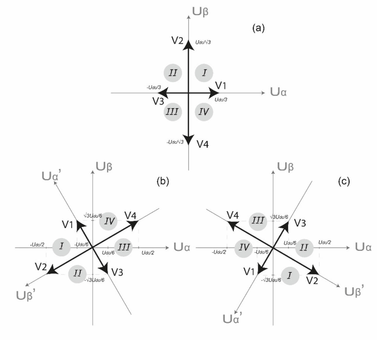
Figure 2.
Voltage vectors in the αβ plane. (a) Fault in a, (b) fault in b, and (c) fault in c.
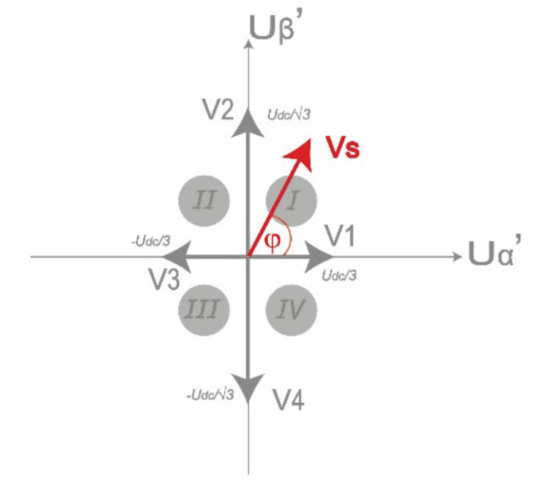
Figure 3.
Common voltage vectors in α′β′ plane.
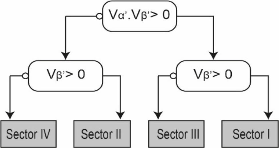
Figure 4.
Flowchart of sector identification.
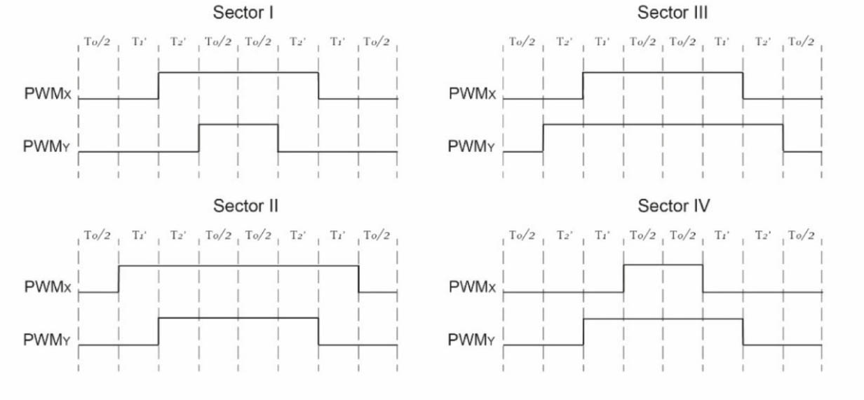
Figure 5.
Optimal switching patterns for the four sectors. PWM, pulse width modulation.
Table 6.
Summarised switching states for the three faulty cases.
| Fault in a | Fault in b | Fault in c | ||||
|---|---|---|---|---|---|---|
| Sx | Sy | S x | Sy | S x | Sy | |
| Sb | Sc | Sc | Sa | Sa | Sb | |
| V1 | 0 | 0 | 0 | 0 | 0 | 0 |
| V2 | 1 | 1 | 1 | 0 | 0 | 0 |
| V3 | 1 | 1 | 1 | 1 | 1 | 1 |
| V4 | 0 | 0 | 0 | 1 | 1 | 1 |
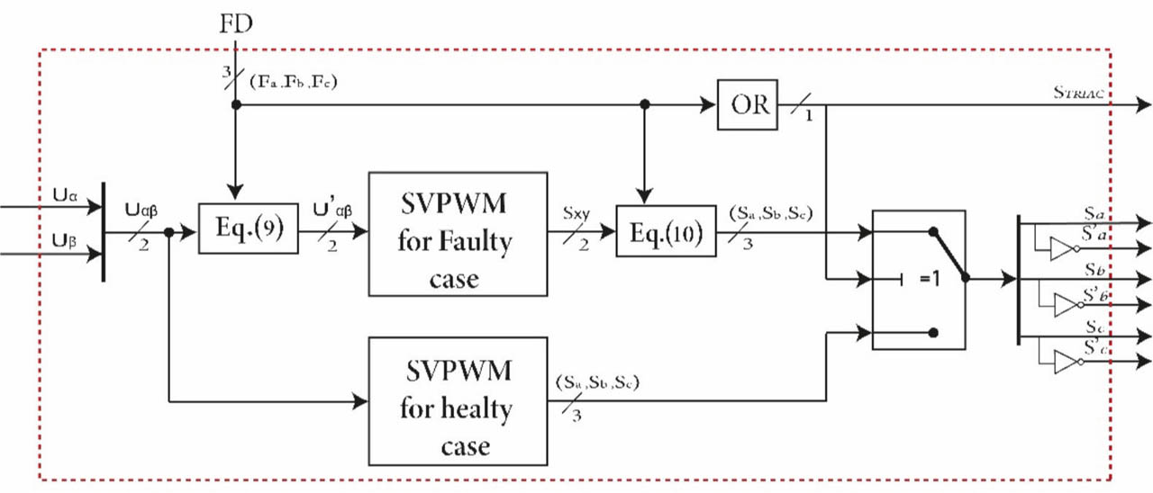
Figure 6.
Proposed consolidated SVPWM control block diagram. SVPWM, space vector pulse width modulation.
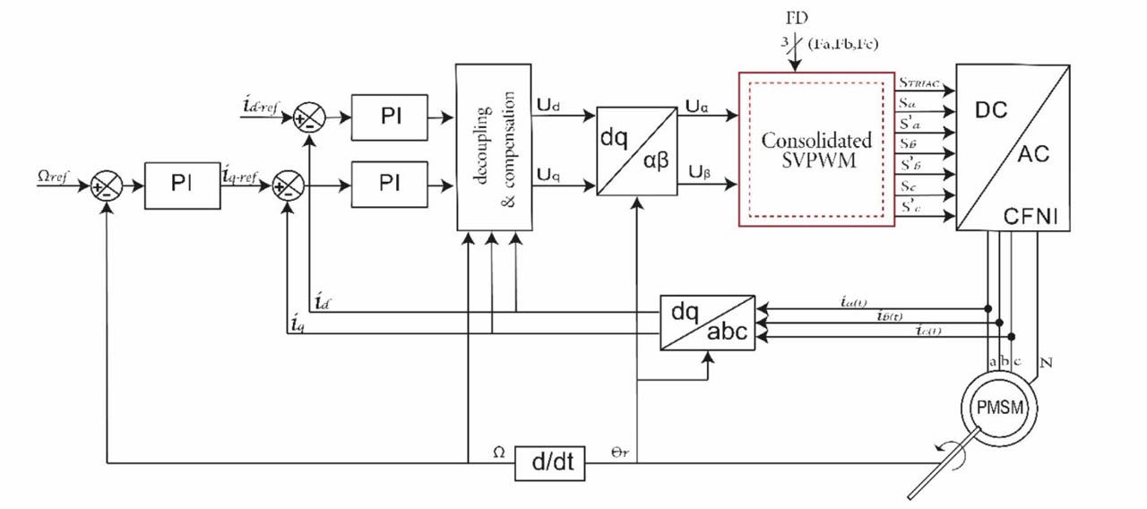
Figure 7.
Proposed single-phase FTC block diagram. CFNI, capacitor-based four-leg neutral-point-connected inverter; FTC, fault-tolerant control; PMSM, permanent magnet synchronous motor; SVPWM, space vector pulse width modulation; PI, proportional-integral.
Table 7.
System parameters.
| Parameters | Values |
|---|---|
| DC-voltage | 220V |
| Cbus | 4.4 mF |
| PWM frequency | 16 kHz |
| Rated power | 1,100 W |
| Rated speed | 3,000 rpm |
| Resistance and inductance | 2.875 Ω and 8.5 mH |
| Pole pairs | 4 |
| Viscous friction | 0.001 Nms |
| Rotational inertia J | 0.0008 kg·m2 |
| Permanent magnet flux | 0.175 Wb |
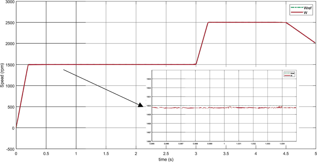
Figure 8.
Speed response before and after a fault occurs in phase a at 1 s.
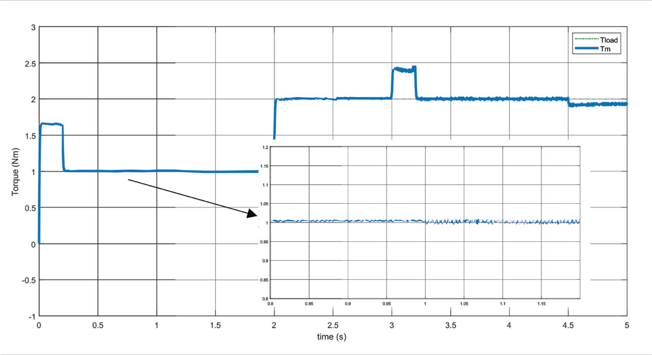
Figure 9.
Torque response before and after a fault occurs in phase a at 1 s.
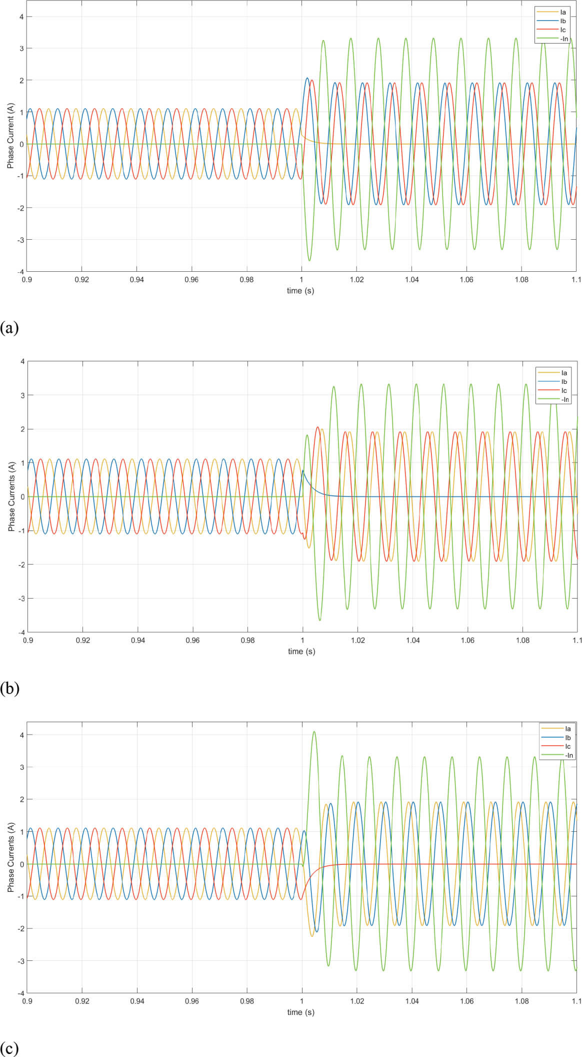
Figure 10.
Current response before and after a fault occurs at 1 s, (a) in phase a, (b) in phase b, and (c) in phase c.
Table 8.
Current amplitudes and phase displacements in the three faulty scenarios.
| Amp. | Deph. | Amp. | Deph. | Amp. | Deph. | Amp. | Deph. | |
|---|---|---|---|---|---|---|---|---|
| ia | iN | 0 | 0 | - | ||||
| ib | iN | 0 | - | |||||
| ic | iN | 0 | - | |||||
| in | 0 | - | 3iN | 0 | 3iN | 0 | 3iN | 0 |
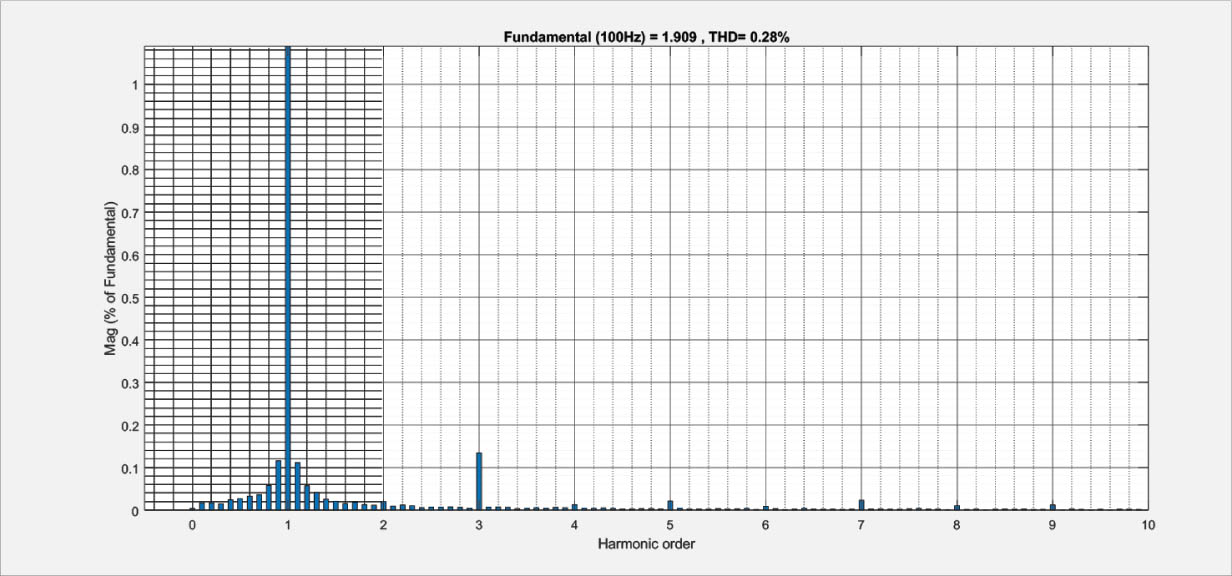
Figure 11.
Current THD in faulty case. THD, total harmonic distortion.