
1. Introduction
Switched reluctance motors (SRMs) have gained increasing attention in recent years due to their relatively simple construction, low production cost and wide constant-power operating range at high speeds, making them an attractive alternative to synchronous permanent magnet motors (SPMMs) in electric mobility applications. In addition to being cost-competitive due to the absence of permanent magnets in the rotor, SRMs exhibit superior thermal dissipation characteristics as a result of their doubly salient stator and rotor structure and the absence of rotor windings. Moreover, there is no risk of permanent magnet demagnetisation at high operating speeds, nor is there a need for a retaining sleeve or bandage to secure magnets on the rotor. Although synchronous permanent magnet motors are available in various designs, including diverse rotor topologies, they are inherently subject to certain drawbacks, such as cogging torque and angular misalignment, which are particularly critical in closed-loop control systems (Sarac and Stefanov, 2020). To address these issues, several authors have proposed optimisation techniques based on genetic algorithms (GAs) and Cuckoo Search to reduce torque ripple (Cvetkovski and Petkovska, 2021). In addition, methods for detecting angular misalignment have been developed based on the analysis of the stator phase current signal. The proposed and comparatively evaluated approaches include spectral analysis and wavelet analysis of the stator current, the stator current envelope and the stator current space vector module (Pietrzak and Wolkiewicz, 2021). Despite the relatively simple construction of switched reluctance motors, developing an accurate analytical model remains a challenging task due to the strong non-linearities arising from the position-dependent inductance profile and the torque production mechanism, which depends on both the inductance variation with rotor position and the square of the stator current. A geometry-based analytical model, incorporating the machine geometry, material magnetisation characteristics and fringing effects, was developed and has been shown to be both accurate and straightforward (Jayapragash and Chellamuthu, 2015). Both offline-trained and online-trained radial basis function (RBF) neural network models were proposed to estimate SRM flux linkage under running conditions. The performance of the proposed models was validated through simulation and experimental investigations conducted on a 12/8 switched reluctance motor prototype (Cai and Deng, 2013). The operating characteristics of switched reluctance motors are strongly influenced by the configuration of the stator and rotor poles (Kachapornkul et al., 2022). The most commonly used configurations are 6/4 and 8/6 stator-to-rotor pole combinations. To prevent a situation where all stator poles simultaneously align with the rotor poles—resulting in zero reluctance torque—the number of stator poles must always exceed the number of rotor poles. The design of electrical machines, including switched reluctance motors, is inherently a multivariable problem involving numerous interrelated parameters. Mamede et al. (2019) investigate the effects of stator and rotor pole arcs, stator and yoke thicknesses, inner and outer stator diameters, air-gap length and the number of winding turns on motor torque. Although general guidelines for high-speed switched reluctance motors recommend an air-gap length of 0.2–0.5 mm, selecting an appropriate air gap is critical to avoid degrading motor performance. An increased air-gap length raises the maximum phase current required to achieve the desired output power (Deepak et al., 2022; Kocan et al., 2021). Kocan et al. (2021) analysed the impact of design parameters of a switched reluctance motor on the output power of a 10 kW, 100,000 rpm machine. Their initial design revealed that modifications to the rotor geometry were necessary to achieve the required power output which contributed to the reduced windage losses. Further improvement in motor efficiency is achieved by reducing the rotor diameter, leading to decreased windage losses. In addition, selecting materials with lower losses contributes to increased overall efficiency. The operation of switched reluctance motors, especially at high speeds, is characterised by significant vibrations, with torque ripple occurring throughout the entire operating range due to the doubly salient structure of the stator and rotor. This limitation constrains the use of SRMs in electric mobility applications. Torque ripple can be mitigated either by modifying the motor’s physical construction or by implementing suitable control strategies within the drive system. According to Lan et al. (2021), current profiling and optimisation of the turn-on and turn-off angles represent two effective control strategies for mitigating torque ripple in switched reluctance motors. Lukman and Ahn (2021) present a motor design methodology aimed at minimising torque ripple. The proposed approach consists of two key elements: a non-uniform air gap on the rotor pole face and a hole introduced within each non-uniform region to maintain the desired air-gap saturation level. A higher number of stator and rotor poles contributes to increased average torque and reduced torque ripple (Melo and Araújo, 2020). However, such a design requires a lot of switching devices in the drive circuit, leading to higher costs and increased switching losses. The choice of steel lamination material can significantly impact the efficiency of SRMs. Yaşa et al. (2018) analyse a switched reluctance motor designed for high-speed spindle applications employing HiperCo material to enable higher magnetic flux saturation. The study demonstrates that the proposed motor configuration achieves increased power density without compromising robustness, reliability or cost-effectiveness. Moreover, the reported efficiency of the 1.7 kW SRM ranges between 70% and 80% across a wide speed range. Another approach involving the use of alternative materials instead of conventional steel laminations is investigated by Przybylski (2023), where soft magnetic composite powders are utilised in the motor core. The analysis demonstrates that the application of soft magnetic powders can contribute to an improvement in overall motor efficiency. Motor efficiency is strongly influenced by appropriate design optimisation. Parameters such as machine length (ML), air-gap length and the number of winding turns can be systematically adjusted to improve overall performance, as reported by Song et al. (2011). Another approach to efficiency improvement, based on stator reconstruction, was proposed by El-Kharashi and Hassanien (2012). In this method, the magnetic flux paths are shortened by incorporating each pair of stator teeth into a single magnetic circuit. As a result, the flux no longer traverses certain regions of the stator back iron, leading to a reduction in core losses and, consequently, an improvement in overall efficiency. Winding design can have a significant impact on torque ripple. Ma et al. (2014) demonstrate that employing a distributed winding in a switched reluctance motor reduces the torque ripple coefficient and increases torque output compared to a conventional winding configuration. Switched reluctance motors are most commonly supplied by asymmetric half-bridge converters, in which each phase is controlled by two power transistors and two diodes, as reported by Abdel-Aziz et al. (2024) and Fang et al. (2021). Fang et al. (2021) investigate various control strategies for switched reluctance motors, including both direct and indirect torque control methods, alongside three approaches for vibration suppression. Additionally, Juarez-Leon and Bilgin (2025) design, develop and experimentally validate a 10-kW silicon-carbide (SiC)–based converter topology. The proposed converter achieves a peak efficiency of 97.03% at the power factor correction stage and 98.90% at the motor drive stage under nominal power conditions. Switched reluctance machines are also employed in generator applications, where efficiency remains a parameter of paramount importance. Zan et al. (2021) proposed a control strategy based on differential evolution as an optimisation mechanism aimed at enhancing the generating capacity and reliability of multi-machine power generation systems from the perspective of efficiency improvement. The proposed approach readjusts the reference current of each parallel-connected generator in order to shift its operating point, thereby enabling efficiency optimisation of the overall parallel generation system.
According to the reviewed literature, the efficiency optimisation of switched reluctance motors has been investigated through the optimisation of ML, air-gap length and the number of winding turns, as well as through modifications of the stator winding, the use of alternative materials for steel laminations and the analysis of the effects of turn-on and turn-off angles on motor efficiency. Therefore, the authors of this paper adopted four design variables which, according to the reviewed literature, have not previously been optimised simultaneously: ML, number of winding turns and the ratio of pole arc to pole pitch for both the stator and rotor, referred to as the stator and rotor pole embrace (EMBS and EMBR respectively). These variables are selected after considering practical manufacturability, as the optimised design requires no additional cost or specialised tools. All four parameters are conventional design variables that can be readily adjusted during the production process, thereby avoiding complex solutions that are not always cost-effective. In this paper, a 10 kW switched reluctance motor rated for 10,000 rpm is modelled in Ansys using data provided by the manufacturer, Kaskod Mtronix, Loksa, Estonia. A parametric analysis is performed by selecting four key design parameters, each varied within predefined limits. The parameters include ML, number of winding turns and stator and rotor pole embrace. By varying these parameters simultaneously, a total of 9,408 motor models are generated. Analysis of the generated models revealed variations in their rated speeds, as the operating speed of a switched reluctance motor depends, among other factors, on its geometry. In particular, the design of the stator and rotor poles—including their size, shape and overall configuration—affects the inductance profile. Since motor torque is directly related to the inductance profile, these design variations have a direct impact on the achievable motor speed. In addition to speed, the efficiency of the generated models is analysed, and several representative models are identified: Model M1, which exhibits the highest efficiency among models with a rated speed of 10,000 rpm; Model M2, which achieves the highest efficiency across all models, irrespective of rated speed; and Model M3, which displays the lowest efficiency among models with a rated speed of 10,000 rpm. The analysis demonstrates that significantly different SRM designs, in terms of operating characteristics, can be obtained by selecting different combinations of the aforementioned design parameters. For Model M1, the influence of each design parameter on motor efficiency is analysed individually. The model is then implemented in Simulink to evaluate the motor’s transient behaviour, with the resulting current, speed and torque profiles compared against those obtained from the Ansys model. This study provides insights into the key design factors affecting the efficiency of switched reluctance motors. Furthermore, the analysis is extended by applying a GA to maximise motor efficiency, using the same set of design variables as in the parametric study but over extended ranges. The results indicate that, although the GA-optimised model achieves the highest efficiency among all evaluated configurations, this maximum efficiency occurs at a speed which is different from 10,000 rpm. This suggests a deviation from the original motor type, SRKM-10T-15N by Kaskod Mtronix, which serves as the baseline for the analysis and optimisation process. Although the switched reluctance motor has a relatively simple construction, it is complex to analyse and optimise due to its non-linear inductance, which varies with rotor position. The selected optimisation variables—stator pole embrace and rotor pole embrace—directly influence the inductance profile and, consequently, the motor’s torque and speed characteristics. The analysis indicates that, although parametric analysis based on parameter sweeping is relatively simple, it enables comprehensive observation of multiple motor performance indicators as output results. This is particularly advantageous in the case of SRMs, where it is necessary to select a motor design that achieves high efficiency while simultaneously satisfying required speed and torque. In contrast, optimisation using GAs for the switched reluctance motor does not inherently ensure that all specified performance requirements are met simultaneously. The analysis indicates that optimisation methods should be carefully selected and applied in accordance with the specific type of motor under consideration. Particular attention must be given to design characteristics, such as the non-linear dependence of inductance on rotor position, which directly influences key operating parameters including speed and torque. These factors are critically important in ensuring that the optimised motor meets the requirements of its intended application.
2. Parametric Models and Analysis
The simulation model in Ansys is based on data from a 10-kW motor supplied by Kaskod Mtronix type SRKM-10T-15N. These motor specifications are used as a reference for developing the software model. The cross-section of half of the machine model is shown in Figure 1. Figure 1 is generated based on the motor geometry defined in Ansys. It illustrates three stator poles and two rotor poles of the half-machine model, along with the stator windings, which are implemented as concentrated windings around the stator poles. The motor is modelled with a 6/4 pole configuration, consisting of six stator poles and four rotor poles. The software model is partially based on the motor’s external dimensions provided by the manufacturer, while the internal geometrical parameters—such as the stator and rotor pole widths, stator and rotor yoke thicknesses and the number of winding turns—are calculated and subsequently implemented in the model. The SRKM-10T-15N motor, together with its catalogue data, serves as the baseline for the optimisation analysis. Specifically, the software model of the switched reluctance motor and its predicted operating characteristics are compared with the corresponding data from the physical SRKM-10T-15N motor. The close agreement between key characteristics—such as phase current, output power, rated speed and rated torque—obtained from both the software and physical models confirms the accuracy of the simulation model. Further validation is performed by implementing parameters derived from the simulation model, including phase resistance and magnetisation characteristics, in the MATLAB/Simulink (Natick, MA, UNITED STATES) environment. The turn-on and turn-off angles of the drive are determined based on the inductance profile of the simulated motor. The transient responses of speed, current and torque obtained from the Simulink model are then compared with those from the original simulation model. The good agreement between these results provides additional verification of the developed simulation model. Motor design often involves numerous design parameters that are correlated and affect the motor operating characteristics. Identifying the optimal design with respect to predefined performance criteria represents a complex task, as each parameter affects motor behaviour in a different manner. Moreover, various combinations of these design parameters yield a large number of possible motor configurations, further increasing the complexity of the optimisation process.
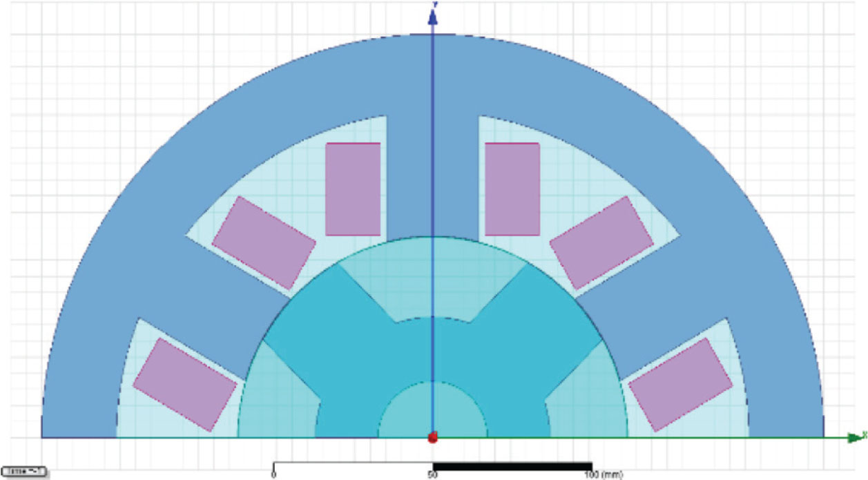
Figure 1.
The motor cross-section.
As the motor design allows for numerous variants, there is potential for further optimisation to achieve improved operating performance. Therefore, four parameters—ML, number of turns per phase winding (WT), EMBS and EMBR—are varied within the boundaries listed in Table 1. The variation in ranges of the varied parameters is kept relatively narrow to ensure that efficiency improvements are achieved cost-effectively, thereby avoiding increased costs associated with a longer motor stack or a higher number of winding turns.
Table 1.
Ranges of parameter variation in optometric analysis.
| Parameter | Range of variation | Step |
|---|---|---|
| ML (mm) | 220–240 | 1 |
| WT (/) | 16–22 | 1 |
| EMBS (/) | 0.45–0.52 | 0.1 |
| EMBR (/) | 0.35–0.42 | 0.1 |
The Ansys software module, (Southpointe 2600 Ansys DriveCanonsburg, PA 15317 USA) Optimetrics, is used to calculate 9,408 motor models generated from different combinations of the four varied parameters. Table 2 presents model M1, which exhibits the highest efficiency among models with a rated speed of 10,000 rpm. Its operating characteristics are compared with the data of the SRKM-10T-15N motor from Kaskod Mtronix. The Ansys software model is developed for the rated operating conditions.
Table 2.
Comparison of M1 and SRKM-10T-15N.
| Parameter | M1 | SRKM-10T-15N |
|---|---|---|
| Power supply (V) | 400 | 400 |
| Rated current (A) | 22.7 | 16 |
| Rated speed (rpm) | 10,000 | 10,000 |
| Nominal torque (Nm) | 9.5 | 9.6 |
| Nominal power (kW) | 10 | 10 |
| Efficiency (%) | 93.09 | / |
Additionally, two more models are selected: model M2, which achieves the highest efficiency regardless of rated speed and model M3, which has the lowest efficiency among models with a rated speed of 10,000 rpm. A comparative overview of all three models, M1–M3, is presented in Table 3. All models are designed with a rated output power of 10 kW to ensure consistent and directly comparable results.
Table 3.
Comparison of models M1, M2 and M3.
| Parameter | M1 | M2 | M3 |
|---|---|---|---|
| ML (mm) | 233 | 240 | 232 |
| WT (/) | 22 | 22 | 16 |
| EMBS (/) | 0.45 | 0.49 | 0.51 |
| EMBR (/) | 0.35 | 0.35 | 0.41 |
| Power supply (V) | 400 | 400 | 400 |
| Rated current (A) | 22.7 | 22.9 | 24.1 |
| Rated speed (rpm) | 10,000 | 8,303 | 10,000 |
| Nominal torque (Nm) | 9.5 | 11.49 | 9.5 |
| Nominal power (kW) | 9.95 | 9.99 | 10 |
| Winding resistance per phase (Ω) | 0.031 | 0.032 | 0.018 |
| Frictional and windage losses (W) | 12 | 9.94 | 12 |
| Iron core loss (W) | 611 | 592 | 1,104 |
| Winding copper loss (W) | 48 | 50 | 31 |
| Diode loss (W) | 7.4 | 8 | 9.5 |
| Transistor loss (W) | 60.8 | 61.6 | 65.3 |
| Total loss (W) | 739.5 | 721.1 | 1,222.2 |
| Input power (kW) | 10.7 | 10.7 | 11.2 |
| Efficiency (%) | 93.09 | 93.3 | 89.05 |
The results in Table 3 reveal that model M3 exhibits the highest total losses, primarily due to the highest iron core losses among the three selected models. This is attributed to the highest current, contributing to increased core losses compared to model M1. In contrast, model M2 shows the lowest iron core losses, which can be ascribed to its longer stack length that reduces magnetic flux density. Model M3 also exhibits the lowest copper losses due to the lowest phase winding resistance. Models M1 and M2 show nearly identical copper losses, resulting from only minor differences in winding resistance and stator current. The magnetic flux density distribution of model M1 is presented in Figure 2.
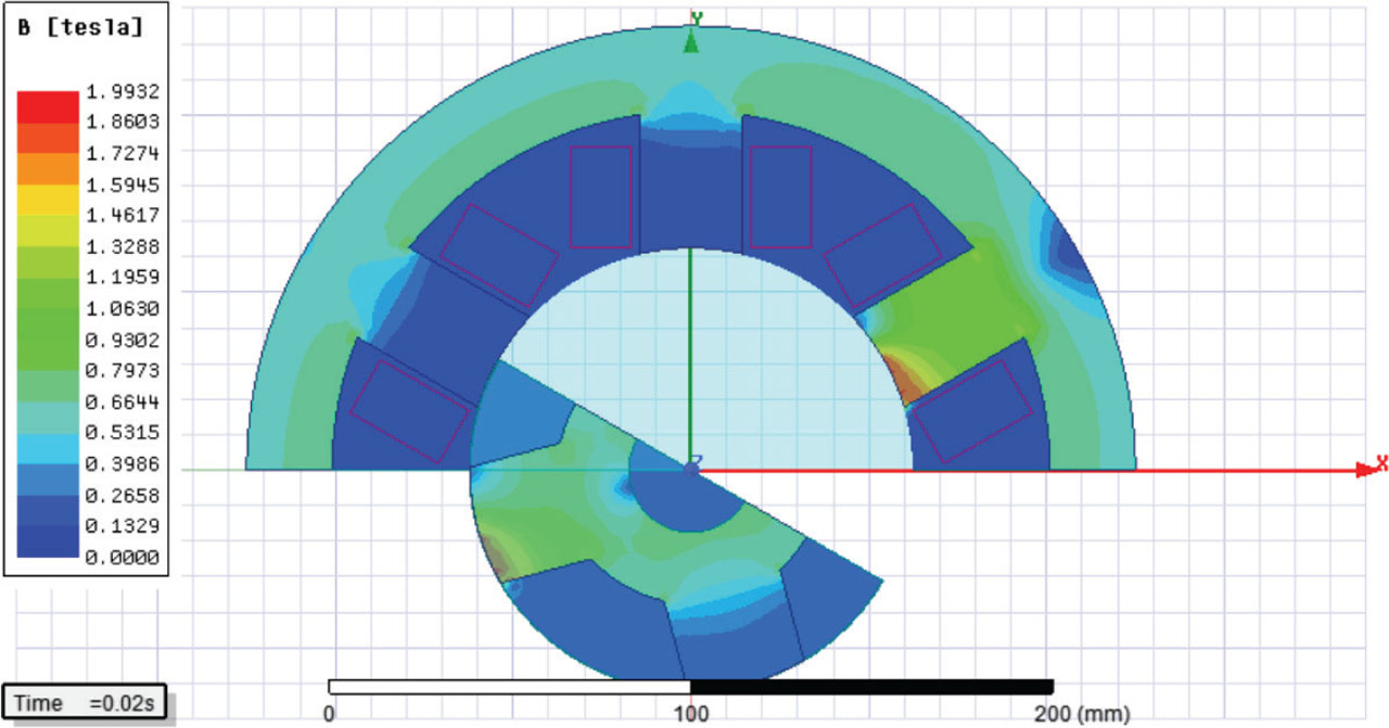
Figure 2.
The flux density distribution of model M1.
Model M1 exhibits small regions of the stator and rotor poles in which the flux density exceeds the knee point of the M19-24G material, used in all three motor models (M1–M3). A similar observation is reported by Abunike et al. (2022). Design experience indicates that limiting the maximum flux density to this level is a recommended practice, as it also contributes to a reduction in acoustic noise (Abunike et al., 2022).
The results presented in Table 3 show that model M2 achieves the highest efficiency. However, this model also exhibits a rated speed of 8,303 rpm and a torque of 11.40 Nm, which differ significantly from the baseline SRKM-10T-15N motor (Table 1). The objective of the optimisation analysis in this study is to identify a design with improved efficiency while maintaining key operating characteristics—such as speed, torque and output power—consistent with those of the reference motor (SRKM-10T-15N). To further investigate this objective, the analysis is extended by applying a GA to maximise motor efficiency. The same four design variables are used, with their corresponding variation ranges defined in Table 4. The optimised solution obtained from the GA is presented in Table 5 and is referred to as Model GA-M.
Table 4.
Ranges of parameter variation in GA analysis.
| Parameter | Range of variation |
|---|---|
| ML (mm) | 115–346 |
| WT (/) | 9–26 |
| EMBS (/) | 0.25–0.75 |
| EMBR (/) | 0.2–0.55 |
Table 5.
Model GA-M from GA optimisation.
| Parameter | GA-M |
|---|---|
| ML (mm) | 328.7 |
| WT (/) | 24.6 |
| EMBS (/) | 0.395 |
| EMBR (/) | 0.358 |
| Power supply (V) | 400 |
| Rated current (A) | 22.4 |
| Rated speed (rpm) | 7,134 |
| Nominal torque (Nm) | 13.35 |
| Nominal power (kW) | 10 |
| Efficiency (%) | 94.9 |
From the results presented in Table 5, it is evident that, under the given conditions (Table 4), model GA-M achieves the highest efficiency of 94.9% at a speed of 7,134 rpm. However, similarly to model M2, model GA-M differs in terms of rated speed and torque from the baseline SRKM-10T-15N motor; thus, the optimised design does not preserve the original operating characteristics of the reference machine. GA optimisation identifies the optimal set of four design parameters that maximise motor efficiency. However, the stator and rotor pole embrace significantly influence the machine inductance and consequently its torque and speed characteristics. The optimised values of ML, WT, EMBS and EMBR, when implemented in the motor model, yield the GA-M configuration with the highest efficiency, but with a substantially lower speed than required. Therefore, parametric analysis provides a more comprehensive perspective for the optimisation of this type of motor, as it enables the simultaneous evaluation of multiple operating characteristics, including efficiency, speed, torque and current. This approach facilitates the selection of a more suitable optimised design that satisfies the overall performance requirements. The single objective function is optimized in GA model, the efficiency. Additional performance criteria, such as cogging torque minimisation, would require a different design approach, including modifications such as an 8/6 pole configuration, rotor skewing, or the optimisation of control variables such as the dwell angle. Figure 3 presents the efficiency of model GA-M as a function of motor speed. This steady-state characteristic is plotted over a range of speeds, with the corresponding efficiency evaluated at each operating point. The results shown in Figure 3 support the data presented in Table 5, confirming that an efficiency of 94.9% is achieved at a speed of 7,134 rpm.
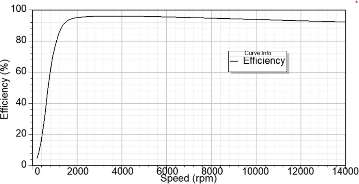
Figure 3.
Efficiency of model GA-M.
The results presented in Table 3 indicate that the four varied parameters significantly affect the motor’s performance characteristics, including speed, torque, current and efficiency. The speed of an SRM is influenced by multiple factors, such as rotor position, turn-on and turn-off angles, applied voltage, machine geometry and back electromotive force (EMF). The motor windings are energised by the drive according to feedback from the rotor position. Consequently, the turn-on and turn-off angles are set based on rotor position, and these angles determine the average torque, which in turn influences the motor speed. The DC link of the drive directly controls the supplied current, which in turn affects the developed torque and ultimately determines the motor speed. Often, SRM analysis is conducted under the assumption that, magnetically, the motor remains unsaturated during operation. If magnetic saturation is neglected, the relation between flux (ϕ) and current (I) can be written as (Texas Instruments, 2020):
The motor inductance L is a function of the position of the rotor, i.e. rotor angle (θ). Substituting Eq. (1) into the equation for magnetic field co-energy (Wc):
and evaluating the integral, the magnetic field co-energy can be written as:Eq. (3) is substituted into the equation for motor torque (T) expressed as a derivative of magnetic field co-energy:
This yields a simplified relationship of torque at a switched reluctance motor:
In this study, the design of the stator and rotor poles—represented by the stator and rotor pole embrace (the ratio of pole arc to pole pitch)—affects the inductance profile and consequently influences both the motor torque and the rated speed. At higher speeds, the motor’s back EMF increases and opposes the applied voltage, potentially exceeding it. This can create challenges in motor control and in achieving the desired speed for a given application. Figure 4 presents the inductance profiles, i.e. the variation of inductance with rotor position expressed in electrical degrees, for all three models (M1–M3) under the rated operating conditions given in Table 3. Figure 4 shows that the inductance profiles differ among the three models, which is expected given the variations in stator and rotor pole geometry for each model. The width of the stator and rotor pole arcs determines the profile of the inductance. Equal pole arcs produce an inductance profile which is triangular with a sharp peak at the aligned position. Wider rotor poles create the flat top on the inductance profile.
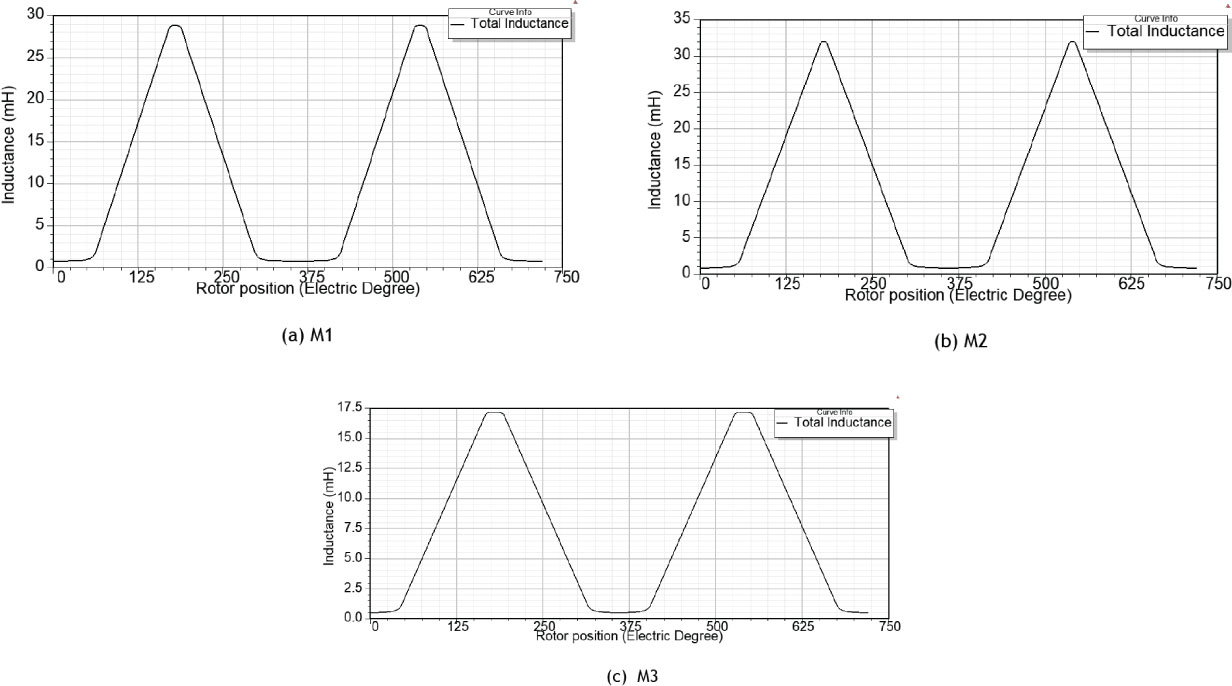
Figure 4.
Inductance profiles of models M1 to M3.
Figure 5 presents the efficiency of models M1–M3 as a function of motor speed in steady-state conditions and supports the data reported in Table 3. Specifically, for each motor model at its rated speed, the corresponding efficiency can be obtained from Figure 5, confirming the efficiency values presented in Table 3. Model M1 is selected for further analysis, as it exhibits the highest efficiency among models with a rated speed of 10,000 rpm and demonstrates sufficient accuracy and close correspondence with the physical motor, SRKM-10T-15N.
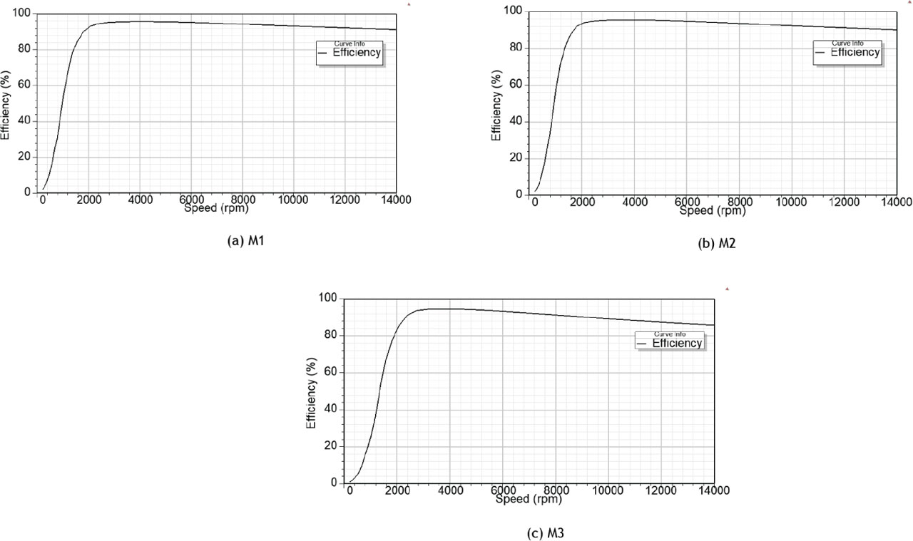
Figure 5.
Efficiency of models M1 to M3.
The analysis highlights the importance of carefully evaluating each of the four design parameters, as well as different combinations of their values, since the resulting motor models can exhibit significant differences in operating characteristics, particularly in terms of speed and efficiency. The influence of each varied parameter on the efficiency of model M1 is presented in Figures 6–9, while the remaining three parameters are kept constant at the values listed in Table 3 for rated operating conditions, namely a supply voltage of 400 V and a rated speed of 10,000 rpm. Figure 6 illustrates the effect of the EMBS on motor efficiency, while the other three parameters are held constant at the values given in Table 3, i.e. EMBR = 0.35, WT = 22 and ML = 233. The EMBS is varied within the limits specified in Table 1. From the results shown in Figure 4, it is evident that higher efficiency can be achieved with a model having the following parameters: WT = 22, ML = 233, EMBR = 0.35 and EMBS = 0.5. This set of parameters corresponds to a model with a rated speed of 8,199 rpm, which differs from the rated speed of the physical motor, SRKM-10T-15N. The impact of the EMBS on efficiency is minimal, as efficiency varies only slightly within the considered range of EMBS, from 93.08% to 93.13%.
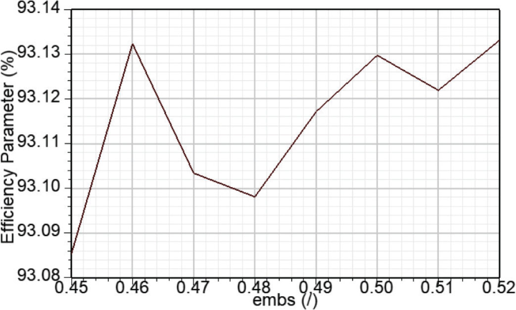
Figure 6.
Impact of EMBS on efficiency. EMBS, stator pole embrace.
The influence of EMBR on motor efficiency is shown in Figure 7. The same methodology as in Figure 6 is applied, where the other three design parameters are kept constant at the values given in Table 3, namely EMBS = 0.45, WT = 22 and ML = 233, while the EMBR is varied within the limits specified in Table 1. The results indicate that an increase in EMBR slightly reduces efficiency. However, across the entire range of EMBR, the efficiency varies only minimally, from 93.09% to 92.91%. The effect of EMBR on efficiency leads to the same conclusion as observed for EMBS, with only a minimal impact on overall motor efficiency.
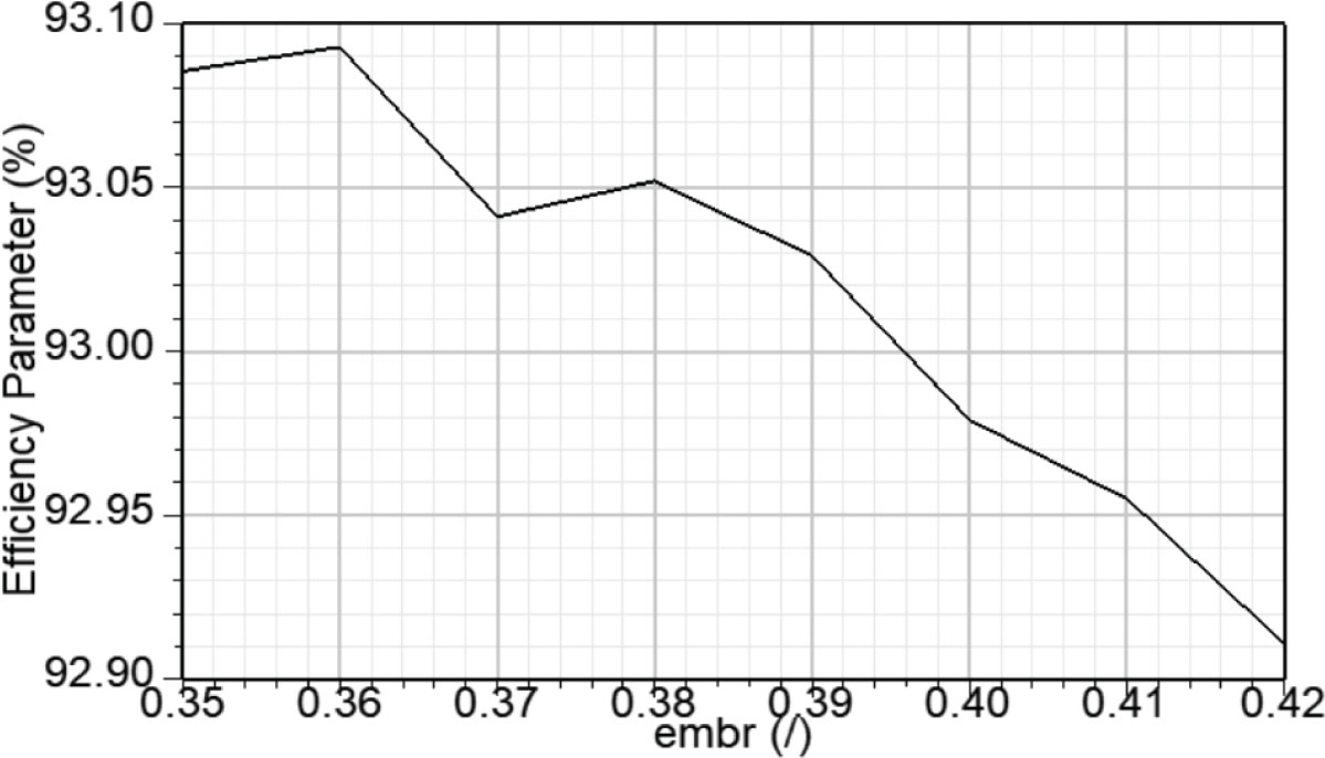
Figure 7.
Impact of EMBR on efficiency. EMBR, rotor pole embrace.
The influence of the WT on efficiency is illustrated in Figure 8. Figure 8 is obtained using the same methodology as in Figures 6 and 7. The results shown in Figure 8 indicate that the number of winding turns significantly affects efficiency. Increasing the number of turns raises the winding resistance but reduces the current. Since copper losses are proportional to the product of resistance and the square of the current, the reduction in current outweighs the increase in resistance, resulting in lower copper losses and higher efficiency. Across the considered range of winding turns, efficiency varies significantly, from 89.2% to 93.09%. At ultra-high speeds, a higher number of turns increases the back EMF, which limits the maximum current and consequently reduces the output power. The number of winding turns should be carefully selected based on the specific application.
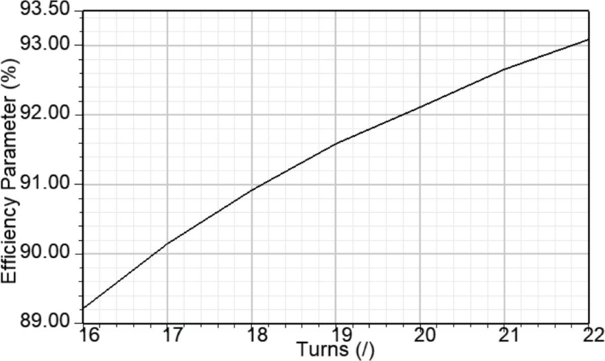
Figure 8.
Impact of winding turns on efficiency.
Figure 9 illustrates the influence of ML on motor efficiency. It is obtained using the same methodology as described for Figures 6 and 7. Increasing the ML improves motor efficiency. In radial-flux machines, a longer machine provides a larger air-gap surface area, which increases the maximum inductance and the resulting electromagnetic force. Consequently, higher torque is produced for the same current level. This trend is confirmed by the results presented in Table 3, where model M2, which has the greatest axial length, exhibits the highest torque and the largest maximum inductance, as shown in Figure 4b. An increased stack length reduces the magnetic flux density, which can consequently lead to lower iron losses and improved efficiency. The high-speed machines employ a 6/4 configuration. Yan et al. (2019) report that increasing the number of stator and rotor poles elevates the flux-density, variation frequency, which in turn increases iron losses and negatively impacts overall machine efficiency. However, the ratio of the motor outer diameter to the stack length is an important design parameter. Depending on the application, either a shorter or a longer stack length may be preferred. In fan applications, a shorter stack is desirable to achieve a compact design, whereas in electric mobility applications, a longer stack length can contribute to higher torque and power output.
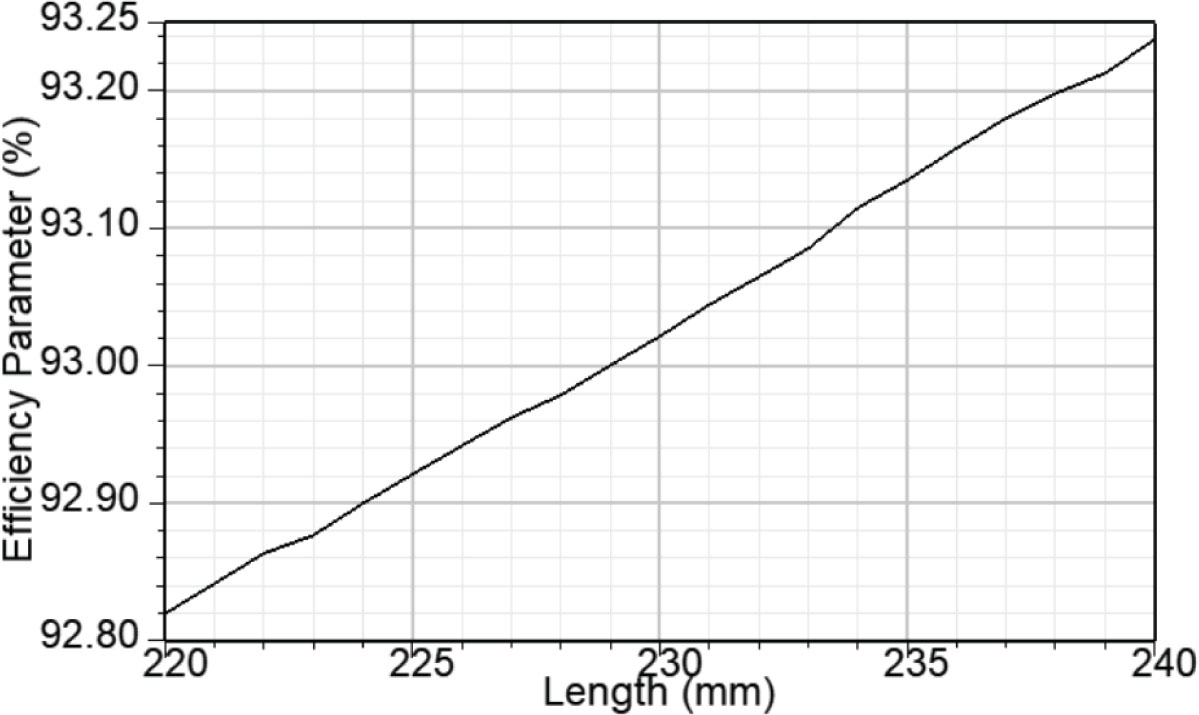
Figure 9.
Impact of ML on efficiency. ML, machine length.
3. Simulink Model and Transient Characteristics
Model M1 is implemented in a Simulink model of a 6/4 switched reluctance motor supplied by an asymmetric half-bridge converter to evaluate the motor’s transient characteristics, since SRM operation without a power converter is not feasible. Accurate Simulink modelling of the SRM requires determination of the turn-on and turn-off angles based on the inductance profile of Model M1. These angles can be optimised to achieve maximum average torque, as reported by Kocan and Rafajdus (2019). Control of a switched reluctance motor is achieved by synchronising the phase current pulses with the rotor position (θ). Positive torque is generated when the phase current is applied during intervals of increasing phase inductance (dL/dθ > 0), whereas regenerative (braking) torque occurs when the current is applied during intervals of decreasing inductance (dL/dθ < 0) (Ćalasan and Vujičić, 2013). The electrical behaviour of the motor is represented by a non-linear model based on its magnetisation characteristics. These characteristics are defined by multiple magnetising curves obtained from the Ansys model and incorporated into the Simulink motor model. The magnetisation characteristics of Model M1 are illustrated in Figure 10.
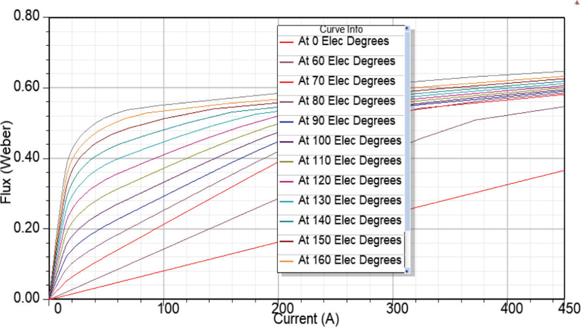
Figure 10.
Magnetisation characteristics of M1.
The Simulink example model of a 6/4 switched reluctance motor is used and modified accordingly to match the analysed model M1 (Mathworks, 2018). In particular, accurate determination of the switching angles and appropriate DC-link sizing are essential to obtaining transient speed, current and torque characteristics which are consistent with those predicted by the Ansys model. The system operates under closed-loop control and is supplied by a three-phase asymmetric power converter comprising three legs, each consisting of two IGBTs and two free-wheeling diodes. During the conduction intervals, the active IGBTs apply a positive source voltage to the stator windings, thereby driving positive phase currents. The switching angles are determined based on the inductance profile of model M1, ensuring that the conduction interval of the switches covers the region of increasing inductance. The inductance profile shown in Figure 4a, from which the switching angles are determined, is presented for rated operating conditions. The Simulink model is likewise analysed under the same rated conditions. Accordingly, in the Simulink model, the turn-on and turn-off angles are set to 14° and 41°(mechanical degrees), respectively. The phase is de-energised before the rotor reaches the aligned position, allowing the current to decay and preventing the onset of negative torque (generator operation). During the free-wheeling intervals, a negative voltage is applied to the windings and the stored magnetic energy is returned to the DC power source through the diodes. The rotor position sensor enables precise control of the turn-on and turn-off angles. Phase currents are independently regulated by three hysteresis controllers, which generate the IGBT drive signals by comparing the measured currents with their reference values. The hysteresis band is typically defined as the tolerance margin above and below the reference current within which the phase current is regulated. The IGBT switching frequency is primarily governed by the width of this band. A narrower hysteresis band reduces torque ripple and acoustic noise; however, it also results in a higher average switching frequency, thereby increasing converter switching losses. In practice, the hysteresis band is commonly selected within the range of 5%–10% of the rated peak current to achieve a trade-off between performance and switching losses. For the analysed model, the hysteresis band is set to 1 A. The reference current is set to 50 A, thereby limiting the motor’s starting current to 50 A (Mathworks, 2018). Figure 11 presents the motor speed as a function of time. All transient characteristics, including speed, current, torque and flux (Figures 12–16), are simulated under a constant load torque of 8 Nm applied to the motor shaft at startup and a moment of inertia of 0.043 kg·m2. The acceleration time depends on the motor’s inertia and the load magnitude. After acceleration, the motor reaches the rated speed of 10,000 rpm, which is consistent with the speed of model M1 reported in Table 2.
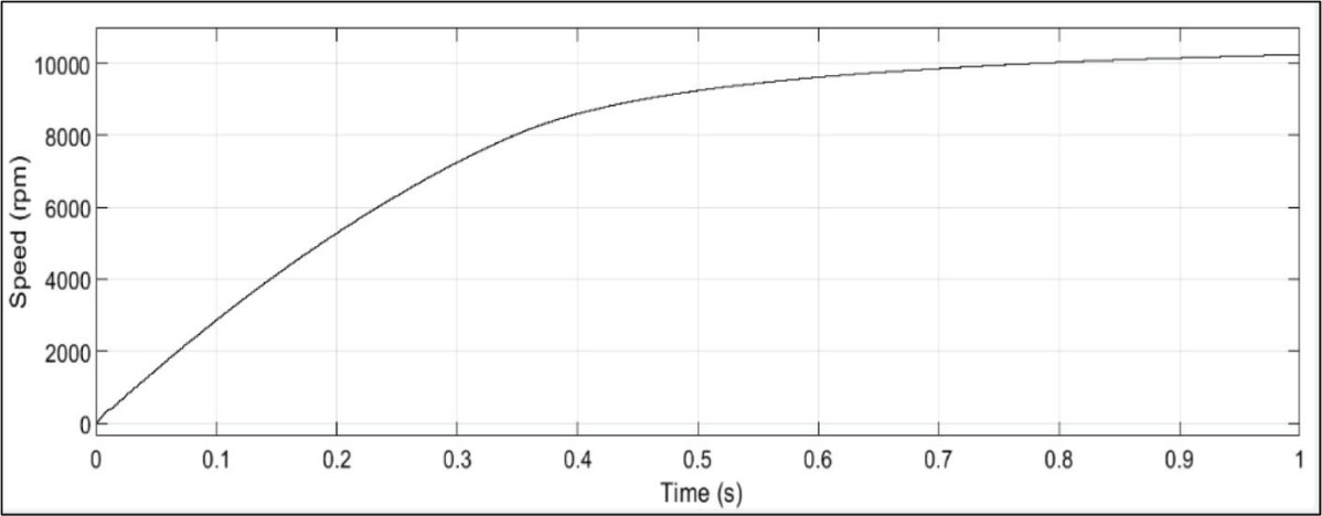
Figure 11.
Transient characteristic of speed.
The transient current characteristics are shown in Figure 12. During startup and acceleration, the current is limited to 50 A by the set reference value. Once the motor reaches the rated speed, the current stabilises at approximately 25 A, which is comparable to the rated current of 22.7 A, calculated for model M1 in the ANSYS simulation (Table 3). An enlarged view of all three-phase currents after the motor reaches the rated speed is presented in Figure 13. From Figure 13, it can be observed that the current has pulse-like waveforms. The current rises when the corresponding phase is energised and decreases when it is de-energised. When the rotor and stator pole are aligned, the inductance reaches its maximum resulting in current to peak before it starts to decrease. The waveform of the phase current, including its amplitude and duration, depends on the selected turn-on and turn-off angles as well as the employed control strategy. Some authors have addressed the problem of estimating the current waveforms required to achieve a desired electromagnetic torque in a switched reluctance motor by introducing a methodology that utilises a transformation from the time domain to the position domain (Bernat et al., 2017).
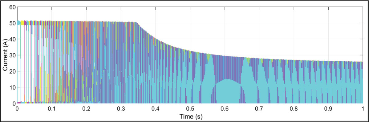
Figure 12.
Transient characteristic of currents.
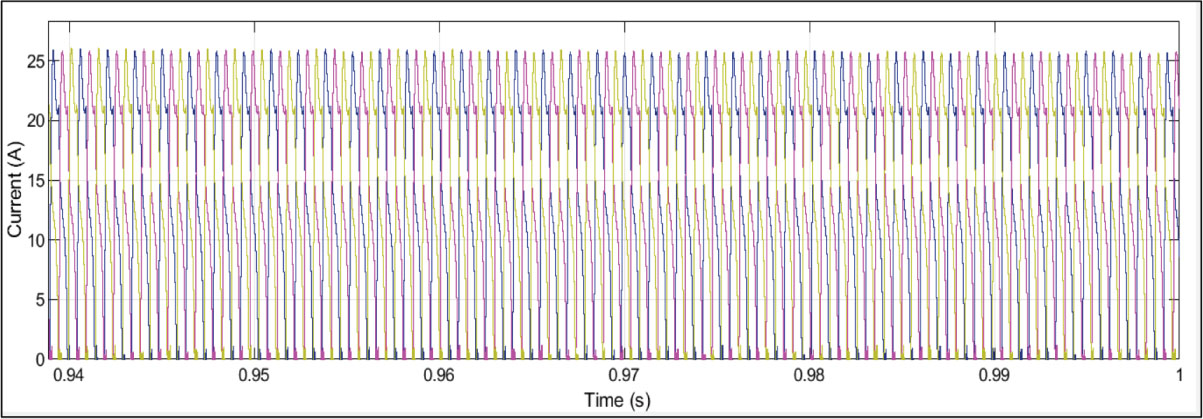
Figure 13.
Enlarged detail of currents.
Figure 14 shows the motor torque. A pronounced torque ripple is observed, resulting from the transitions of current between consecutive phases. As the motor windings are energised sequentially, the rotor poles tend to align with the energised stator poles. This process generates vibrations and acoustic noise due to structural deformations and magnetic torque harmonics, which induce interactions between the stator and rotor. These interactions lead to torque fluctuations, i.e. torque ripple. Consequently, SRM operation is inherently accompanied by noise and vibrations, particularly in the 6/4 configuration compared to the 8/6 configuration. Although the 8/6 configuration reduces torque ripple and noise, it requires a more complex drive system. One approach to minimising torque ripple is to skew the rotor poles or to implement advanced control strategies, such as harmonic injection, in a 6/4 variable-flux reluctance machine (Liu et al., 2024). Torque ripple can be reduced by optimising motor control variables, such as the dwell angle (Mathworks, 2025). Proper commutation of the motor phases is essential for SRM operation, with each switching sequence controlling the turn-on and turn-off of the corresponding phase. The duration of phase activation, defined by the turn-on and turn-off angles, is referred to as the dwell angle. A larger dwell angle contributes to a reduction in torque ripple. However, because the current pulses overlap more, the motor’s power consumption increases, resulting in lower efficiency. Conversely, at smaller dwell angles, the overlap of current pulses is reduced, lowering power consumption and improving efficiency. However, the higher torque ripple resulting from smaller dwell angles can impair motor performance and restrict its use in electric mobility applications. In the analysed Simulink model, the turn-on and turn-off angles are determined based on the inductance profile of model M1, ensuring that the conduction interval covers the region of increasing inductance of the rotor. However, this strategy may lead to increased torque ripple, considering the previously discussed relationship between dwell angle and torque ripple, where smaller dwell angles tend to increase torque ripple, while larger dwell angles reduce it. Therefore, the dwell angle is slightly increased by only two mechanical degrees, resulting in reduced cogging torque, as shown in Figure 15. The SRM torque characteristic can be further optimised by applying appropriately pre-calculated turn-on and turn-off angles as functions of motor current and speed (Mathworks, 2018). Further research and analysis should be conducted in this direction.
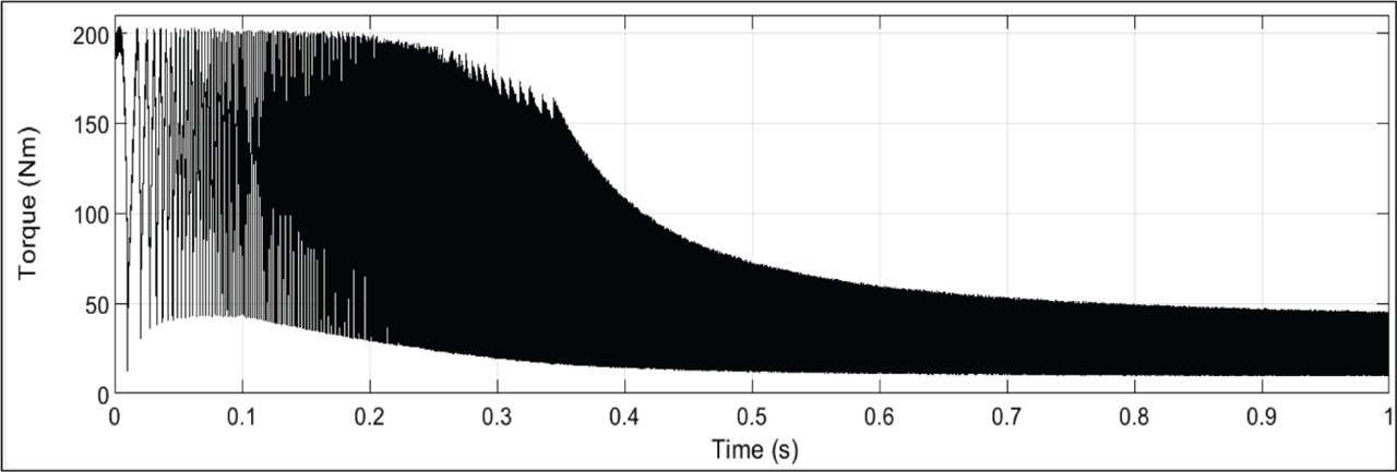
Figure 14.
Transient characteristic of torque.
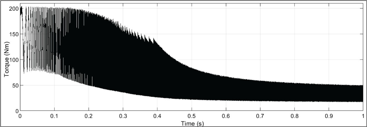
Figure 15.
Transient characteristic of torque with increased dwell angle of control circuit.
Figure 16 presents an enlarged detail view of the flux in the phase windings. According to Mathworks (2018), at speeds above 3,000 rpm, the back EMF becomes sufficiently high so that the converter operates in a voltage-fed mode. In this mode, the power switches are not modulated and remain closed during their active intervals, resulting in a linearly varying flux waveform, as illustrated in Figure 16.
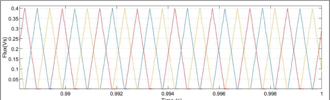
Figure 16.
Enlarged detail view of flux in phase windings.
When comparing the transient characteristics obtained from Simulink with the results from the ANSYS model, it can be observed that the motor speed agrees well between the two methods, with both yielding 10,000 rpm. The phase current shows a slight difference, with 25 A in the transient Simulink simulation and 22.7 A in the ANSYS model. These discrepancies in current and torque are partly due to the approximate modelling of the magnetisation characteristics (Figure 10) in Simulink. Specifically, the magnetisation characteristics of M1 were not directly imported into Simulink; instead, discrete values were extracted from Figure 10 and input into the Simulink model. The accuracy of the magnetisation data in the Simulink model of the motor is therefore highly dependent on the precision of this extraction, which is prone to subjective errors.
4. Conclusion
The switched reluctance motor has emerged as a promising solution for electric mobility due to its cost-effectiveness, robustness and durability. Rising costs and limited availability of permanent magnets have shifted research interest towards SRMs as alternatives to permanent-magnet synchronous motors in electric vehicles. The efficiency of switched reluctance motors represents a critical performance parameter, particularly in the context of ongoing global efforts to reduce electricity consumption and enhance the energy efficiency of electrical systems and devices. Therefore, understanding SRM design and the parameters that influence motor efficiency is essential for further advancement of this technology and its practical applications. The paper emphasises the necessity of a systematic and careful evaluation of various combinations of design parameters, as these combinations generate a wide range of motor models with distinct operating characteristics. The analysis presented in this paper shows that the motor inductance profile, and consequently, the developed torque and speed, depend on the geometry of the stator and rotor poles—for example, the pole embrace, defined as the ratio of pole arc to pole pitch. Among the four design parameters analysed—EMBR, EMBS, number of stator winding turns and ML—the number of winding turns has the most significant effect on motor efficiency, followed by ML. In contrast, the impact of stator and rotor pole embrace on efficiency is negligible. The designed model (ANSYS model) used for the above analysis was validated by inputting its data—such as the stator winding phase resistance and magnetisation curves—into a Simulink model. The Simulink model complements the analysis by enabling the evaluation of transient characteristics, including speed, current and torque, based on the motor model incorporating the magnetisation characteristics obtained from the Ansys model. Furthermore, the Simulink implementation includes the appropriate drive system required for proper motor operation. Accurate determination of the switching angles is essential to ensure consistency and comparability of the results with those obtained from the Ansys model. The results obtained from the Simulink simulation show good agreement with those from the ANSYS model. Further research should focus on analysing and improving motor design and optimising the control variables to minimise torque ripple, as well as evaluating other design parameters such as air-gap length and its impact on motor performance. Additional research directions include the application of multi-objective optimisation techniques that simultaneously consider efficiency and cogging torque, achieved through targeted design modifications. Such an approach would enable the development of optimised motor models that meet high-efficiency requirements while minimising cogging torque, which is critically important in electrical mobility applications.
Further work should also involve the physical realisation and experimental validation of the optimised motor designs. This step would provide a robust foundation for assessing their practical performance. It is expected that real-world prototypes will exhibit deviations from simulated results due to manufacturing constraints, material losses, mechanical friction and additional losses within the drive system. Nevertheless, simulation-based models serve as a starting point for optimisation, offering valuable insights into design parameters that can significantly enhance motor efficiency.