

Figure 1.
The experimental system. DAQ, data acquisition; GUI, graphical user interface.

Figure 2.
Block diagram of the experimental system. DAQ, data acquisition.
Table 1.
Typical specifications of the JGA25-370 12 V encoder gear motor.
| Motor type | Brushed DC gear motor |
|---|---|
| Rated voltage | 12 V DC |
| Motor diameter | 25 mm |
| Motor model | 370 |
| Encoder type | Quadrature Hall-effect encoder |
| Encoder channels | A and B (90° phase shift) |
| Encoder supply voltage | 3.3–5 V DC |
| Encoder pulses | Usually 11 pulses/revolution (PPR) at the motor shaft |
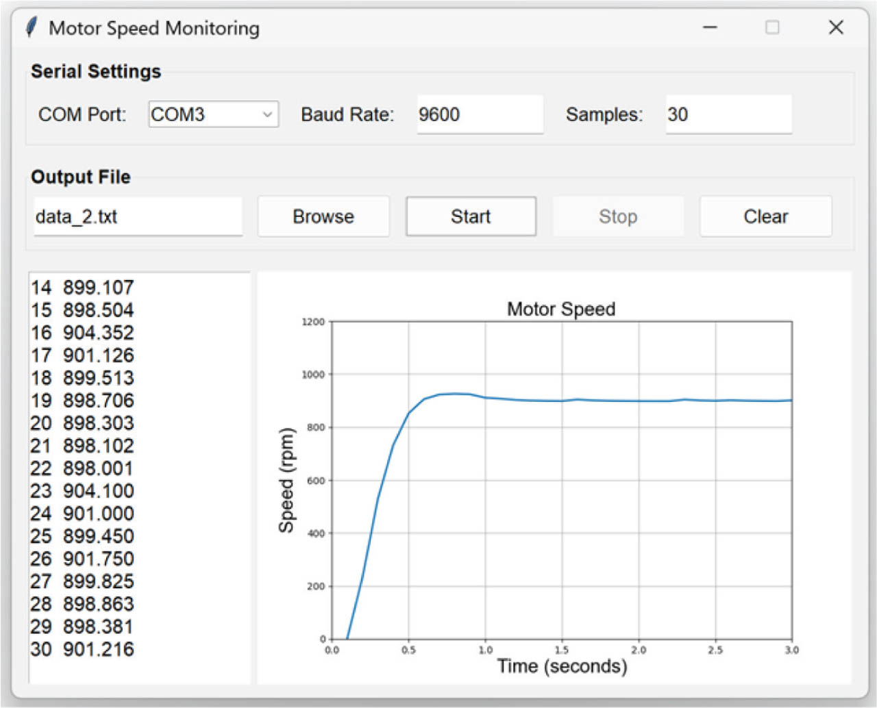
Figure 3.
GUI of the DAQ software. DAQ, data acquisition; GUI, graphical user interface.

Figure 4.
Speed response of the DC gear motor to a step input in duty cycle from 0% to 100%.
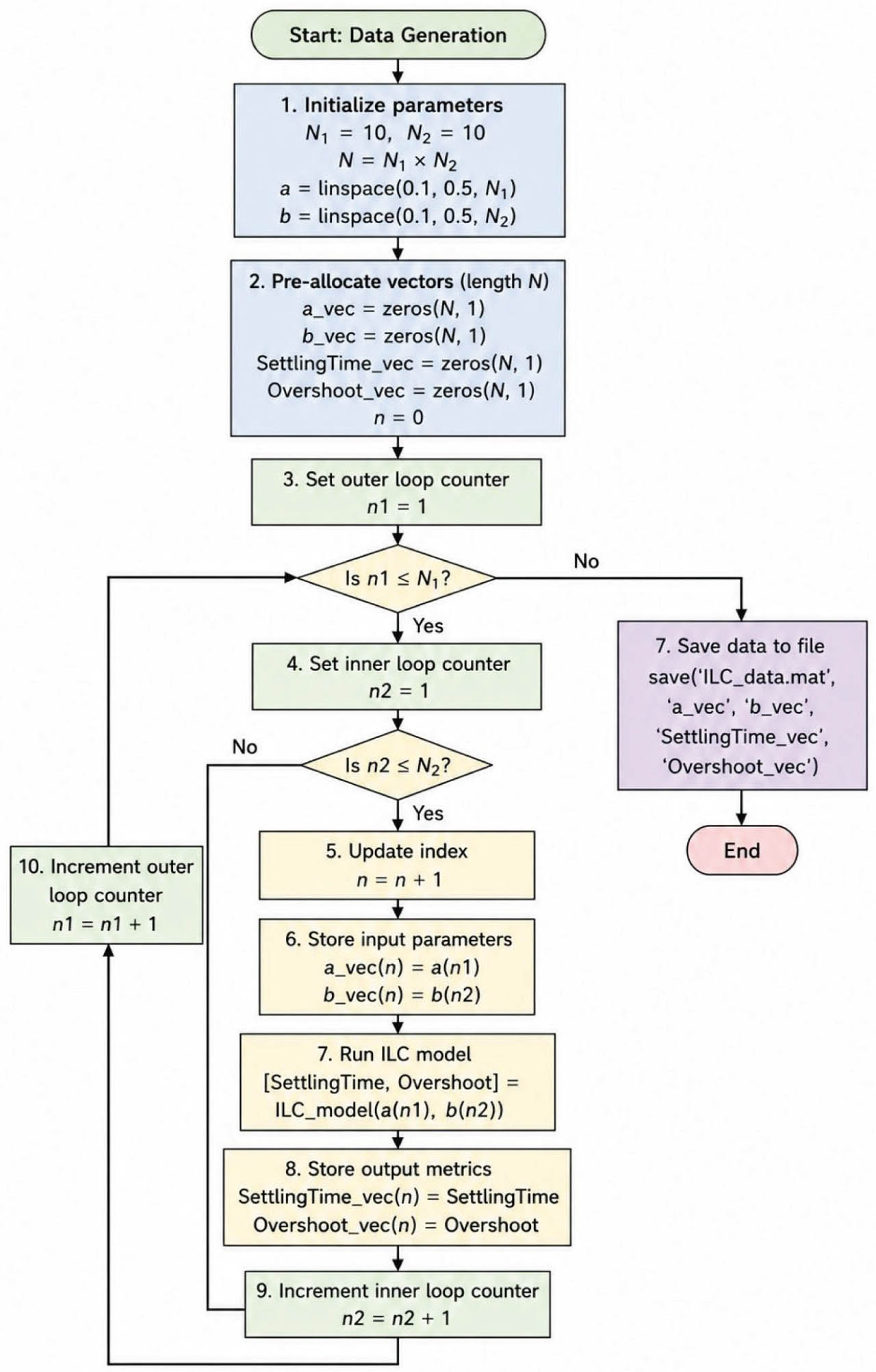
Figure 5.
Flowchart for generating the dataset using MATLAB. ILC, iterative learning control.

Figure 6.
Log evidence versus number of hidden nodes.
Table 2.
Changes of the hyperparameters according to five re-estimation periods.
| Re-estimation period | α | β |
|---|---|---|
| 1 | 0.06818 | 154.24078 |
| 2 | 0.09396 | 152.98557 |
| 3 | 0.15781 | 150.32572 |
| 4 | 0.37790 | 147.54382 |
| 5 | 0.45917 | 146.92314 |

Figure 7.
Principle of determining the gains of the ILC controller using a trained BNN. BNN, Bayesian neural networks; ILC, iterative learning control.

Figure 8.
Flowchart of the simulation of DC gear motor control using a PD-type ILC. ILC, iterative learning control; PD, proportional-derivative.
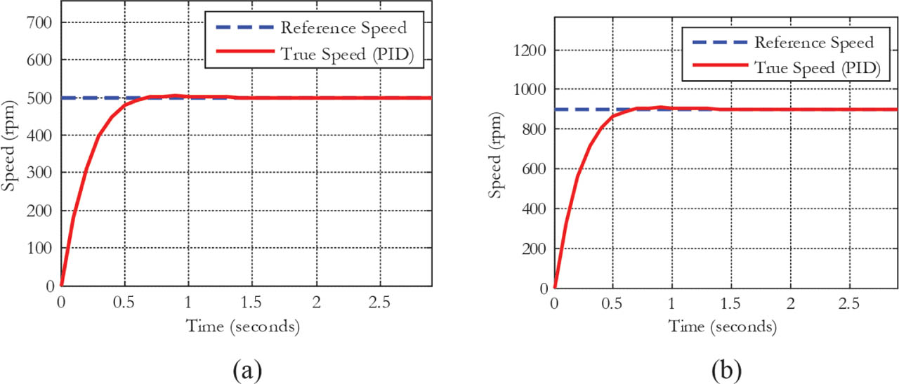
Figure 9.
Simulated motor speed responses to reference speeds of 500 rpm (a) and 900 rpm (b).
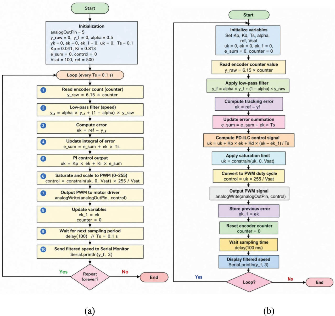
Figure 10.
Flowcharts for implementing the PID controller (a) and the ILC controller (b) on the Arduino Nano. ILC, iterative learning control; PD, proportional-derivative; PI, proportional-integral; PWM, pulse-width modulation.

Figure 11.
Block diagram of the ILC-based DC gear motor control system. ILC, iterative learning control; PD, proportional-derivative; PWM, pulse-width modulation.
Table 3.
The gains of the ILC controller obtained using the minimum values of the settling time and overshoot vectors with a trained BNN.
| Min(settling time vector) | Min(overshoot vector) | KP, ILC | KD, ILC |
|---|---|---|---|
| 0.4625 (s) | 0 (%) | 0.037 | 0.003 |

Figure 12.
True motor speed responses to reference speeds of 500 rpm (a) and 900 rpm (b). BNN, Bayesian neural networks; BNN-ILC, BNN-based ILC; ILC, iterative learning control; PI, proportional-integral.