
Figure 1.

Figure 2.
Figure 3.
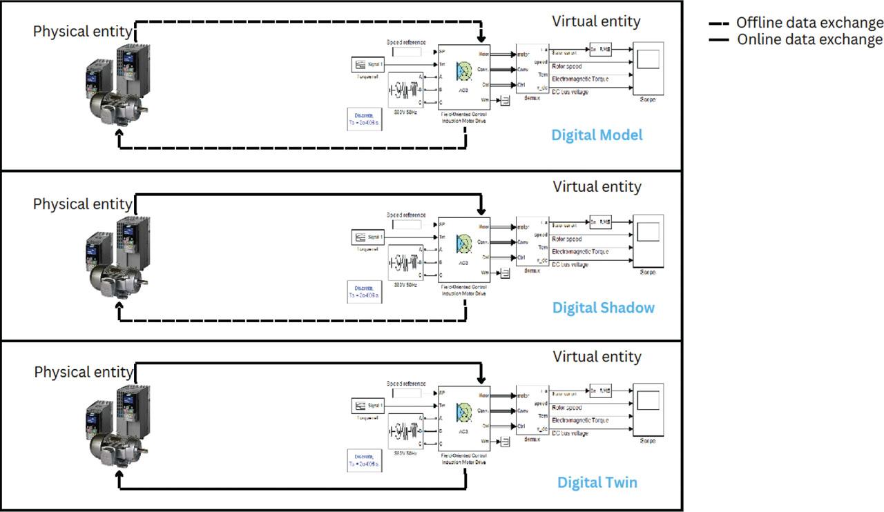
Figure 4.

Figure 5.
Figure 6.
Criteria used to classify digital model, digital shadow DT integration levels in electric drive applications_
| Criterion | Digital model | Digital shadow | DT |
|---|---|---|---|
| Physical-to-virtual data flow | No automatic physical-to-virtual flow | Yes | Yes |
| Online model update | No | Yes | Yes |
| Synchronisation assessment | No or offline only | Yes | Yes |
| Virtual-to-physical decision path | No | No | Yes |
| Typical ED example | Offline Simulink/FEM model | EKF-based monitoring or fault diagnosis | Synchronised model with supervisory action or maintenance decision |
Classification of DT studies in ED: Strengths and limitations_
| Group | References | Common strength | Common limitation |
|---|---|---|---|
| Online monitoring and digital shadow studies | Wang et al. (2019); Cherifi et al. (2022); Brandtstaedter et al. (2018); Ebadpour et al. (2023); Bouzid et al. (2020); Rjabtsikov et al. (2021) | Use online measurements, model updating, observers, reduced-order models, or physics-based simulation to monitor the physical system and improve consistency between measured and simulated behaviour. | Mainly support monitoring, state estimation, fault notification, or operator decision-making. Autonomous virtual-to-physical feedback is generally not demonstrated. |
| Fault diagnosis and classification studies | Adamou and Alaoui (2024); Zayed et al. (2023); Xia et al. (2021); Lopes et al. (2021) | Provide fault-diagnosis approaches using efficiency indicators, FEM-based data generation, hybrid physics-based/data-driven models, optimisation methods machine-learning classifiers. | Focused mainly on fault detection or classification. Corrective action, supervisory control, or closed-loop feedback to the physical drive is not reported. |
| Offline simulation and digital model studies | Gonzalez et al. (2020); Lopes et al. (2021); Bejaoui et al. (2021); Magadán et al. (2023) | Use high-fidelity models, FEM simulations, Simulink-generated datasets, or data-driven models to analyse system behaviour, generate fault data, or support prognostic modelling. | Mostly offline or open-loop approaches. Online synchronisation with the physical system and automatic model updating are limited or absent. |
| RUL prediction and prognostic studies | Sivalingam et al. (2018); Aivaliotis et al. (2019); Lei et al. (2016); Magadán et al. (2023); Venkatesan et al. (2019); Bejaoui et al. (2021) | Estimate degradation, health indicators, damage evolution, or RUL using physics-based, stochastic, ANN/fuzzy-logic, or deep-learning-based prognostic models. | Mainly focused on prediction and health assessment. The prognostic output is generally not connected to operational feedback, control action, or maintenance decision execution. |
| Framework and methodology-oriented studies | Sivalingam et al. (2018); Cherifi et al. (2022); Zayed et al. (2023) | Provide methodological elements for DT development, including DT frameworks, hierarchical modelling, hybrid simulation data-driven diagnostic pipelines. | Full DT implementation remains incomplete because online synchronisation, multiphysics integration, validation, or virtual-to-physical decision paths are not fully demonstrated. |
Demonstrative elements of the IM DT case study_
| Framework element | Implementation in the use case |
|---|---|
| Physical system | Induction motor drive supplied by a Mitsubishi FR-D720S-014SC-EC inverter, with belt-pulley transmission, automotive alternator battery–rheostat adjustable load. |
| Measurement layer | Line voltages, line currents rotor speed were acquired using voltage dividers composed of 2.2 MΩ and 1 kΩ resistors, 0.1 Ω, 3 W, ±1% shunt resistors, TI AMC1300 isolation amplifiers an incremental encoder with a resolution of 1,000 pulses/rev. |
| DAQ and communication | The analogue voltage and current signals were sampled using an NI PCI-6251 DAQ card in combination with an NI BNC-2120 connector block, while the rotor speed was measured from the incremental encoder pulses through counter input ctr0, connected to PFI8 of the DAQ system. |
| Data processing | Time alignment, signal scaling despiking of PWM-induced spikes. |
| Offline commissioning | Electrical parameters estimated from DC, locked-rotor no-load tests; mechanical parameters estimated from coast-down tests. |
| Virtual model | Fifth-order induction motor model expressed in the stationary α -β reference frame |
| Online synchronisation | EKF-based correction of current, flux, speed load-torque states using measured signals. |
| Synchronisation assessment | Residual comparison between measured and estimated current and speed responses. |
| Application layer | Decision support for torque-boost selection based on flux magnitude, current magnitude, speed input power. |