
Recently, Industry 4.0 has digitally transformed the industries. Digital twin (DT), as a part of Industry 4.0, is very important for competitive and economic advantage (Singh et al., 2021). It can be a great tool to increase the competitiveness, productivity efficiency of a company. Internet of Things (IoT) sensors and communication technologies facilitate the integration of the real and virtual worlds by providing real-time data to update the virtual model and ensure it accurately represents the real system. DT brings many advantages in industry, such as reducing the time of development of a product, optimising operations, reducing production and maintenance costs, increasing user engagement fusing information technologies. DT can be used in all phases of a product’s lifecycle, such as the design phase, manufacturing phase, service phase retirement phase, as shown in Figure 1 (Falekas and Karlis, 2021; Liu et al., 2021).
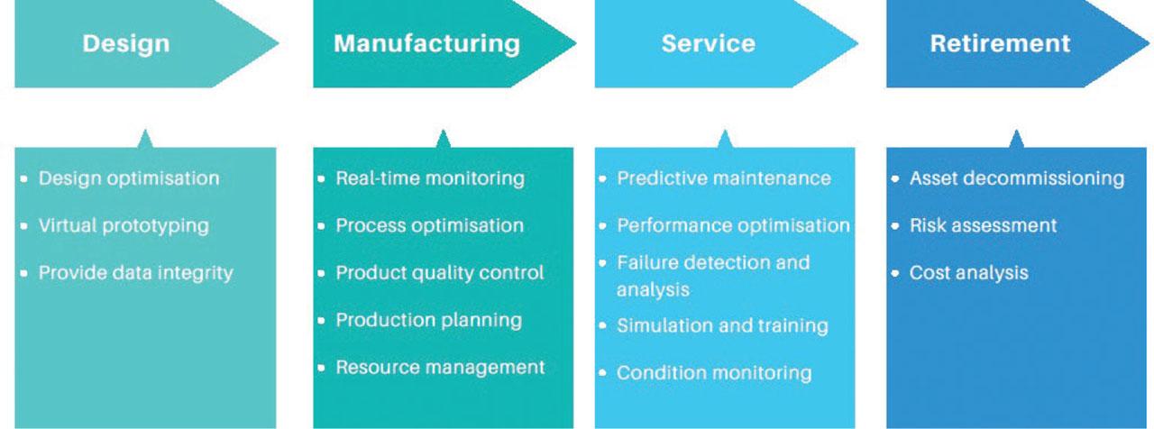
Industrial application of DTs across various lifecycle phases. DT, digital twin.
A difficulty in the DT literature is that the same term is often used for systems with different operating functions. In electric drives (ED), a simulation model, an online observer a supervisory system with feedback functionality are all classified as DTs, although they do not provide the same level of integration. This unclear terminology reduces the practical value of review papers because it becomes difficult to distinguish between studies that only simulate the drive, studies that monitor the drive in real time studies that can influence the physical drive through a feedback mechanism.
DT technology has emerged as a transformative paradigm with applications across a wide range of domains, including smart cities, industrial processes, healthcare, aerospace ocean systems. In smart cities, the integration of IoT sensors and advanced algorithms enables DT to support urban planning, energy optimisation infrastructure management, responding to the rapid growth of connected communities (Fuller et al., 2020; Ibrahim et al., 2022). Within industrial processes, DT facilitates real-time monitoring, design optimisation predictive maintenance by combining real-time and historical data, reducing costs, minimising downtime extending system lifetime (Ibrahim et al., 2022; Katsoulakis et al., 2024). In healthcare, DT is employed for drug testing, disease prevention and treatment, surgical planning patient monitoring, leveraging AI to enhance predictive accuracy, and decision-making (Fuller et al., 2020; Katsoulakis et al., 2024).
In aerospace, DT allows engineers to build virtual prototypes, optimise designs predict failures in engines and airframes, thereby reducing development time and costs while improving safety (Glaessgen and Stargel 2012, Ibrahim et al., 2022). Similarly, in ocean applications, DT integrates diverse datasets, simulation models AI to advance marine monitoring and sustainability initiatives, with projects such as the EU’s (European Union) Blue-Cloud exemplifying large-scale adoption (Barbie et al., 2022; Ibrahim et al., 2022).
Furthermore, DT technology is increasingly being applied to ED, with research focusing on condition monitoring, scenario simulation remaining useful life (RUL) prediction. For condition monitoring, several studies (Adamou and Alaoui, 2024; Bouzid et al., 2020; Brandtstaedter et al., 2018; Cherifi et al., 2022; Ebadpour et al., 2023; Rjabtsikov et al., 2021; Wang et al., 2019) combine physics-based models, including finite-element methods, with updating based on measured data and state or parameter estimation to improve the agreement between simulated and measured behaviour. In this review, these studies are considered building blocks of a DT because they develop the virtual model and the update mechanism that keeps it consistent with the physical system. Accordingly, we classify a work as a digital model when it remains offline, as a digital shadow when operational measurements continuously update the virtual model as a DT only when this online synchronisation is coupled with a feedback loop through which the virtual entity can influence operation, enabling bidirectional interaction.
Simulation-based studies show that physics-based virtual models can generate extensive datasets for fault diagnosis in ED. In our terminology, these works correspond to digital models and do not constitute complete DT implementations unless the virtual model is continuously updated online using operational measurements. In this context, hybrid optimisation and deep-learning frameworks, including sparse denoising autoencoders, transfer learning neural networks, enable accurate classification of multiple fault types in ED systems (Gonzalez et al., 2020; Lopes et al., 2021; Xia et al., 2021; Zayed et al., 2023).
In terms of RUL prediction, research highlights the role of physics-based virtual models for degradation analysis (Aivaliotis et al., 2019; Sivalingam et al., 2018), statistical approaches using stochastic processes, Kalman particle filters (Lei et al., 2016) data-driven models based on deep learning applied to bearing datasets (intelligent maintenance system [IMS], FEMTO-ST institute [FEMTO]-ST, Xi’san Jiaotong University in collaboration with Changxing Sumyoung Technology Co., Ltd. [XJTU–-SY]) (Magadán et al., 2023). Hybrid strategies that combine physics-based and data-driven methods have also been developed for induction motors, achieving high accuracy in fault prognostics (Bejaoui et al., 2021; Venkatesan et al., 2019). Within a DT architecture, these approaches represent key modules of the virtual entity and its analytics layer; when coupled with continuous online data integration, they support monitoring, diagnosis prognostics aimed at improving the performance.
This review provides a comprehensive overview of the applications of DT with a special focus on ED. To collect information, we conducted literature searches. Based on the collected information, the global DTs market (GDTM) size is expected to reach $195.4 billion by 2030, rising at a market growth of 41.3% compound annual growth rate (CAGR) during the forecast period (KBV Research, 2024). This emphasises the increasing popularity of the DT since its introduction. This is reflected in the increasing number of publications that include the keyword DT in titles, abstracts, or as keywords in the Mendeley databases from 2017 to 2025, as shown in Figure 2.
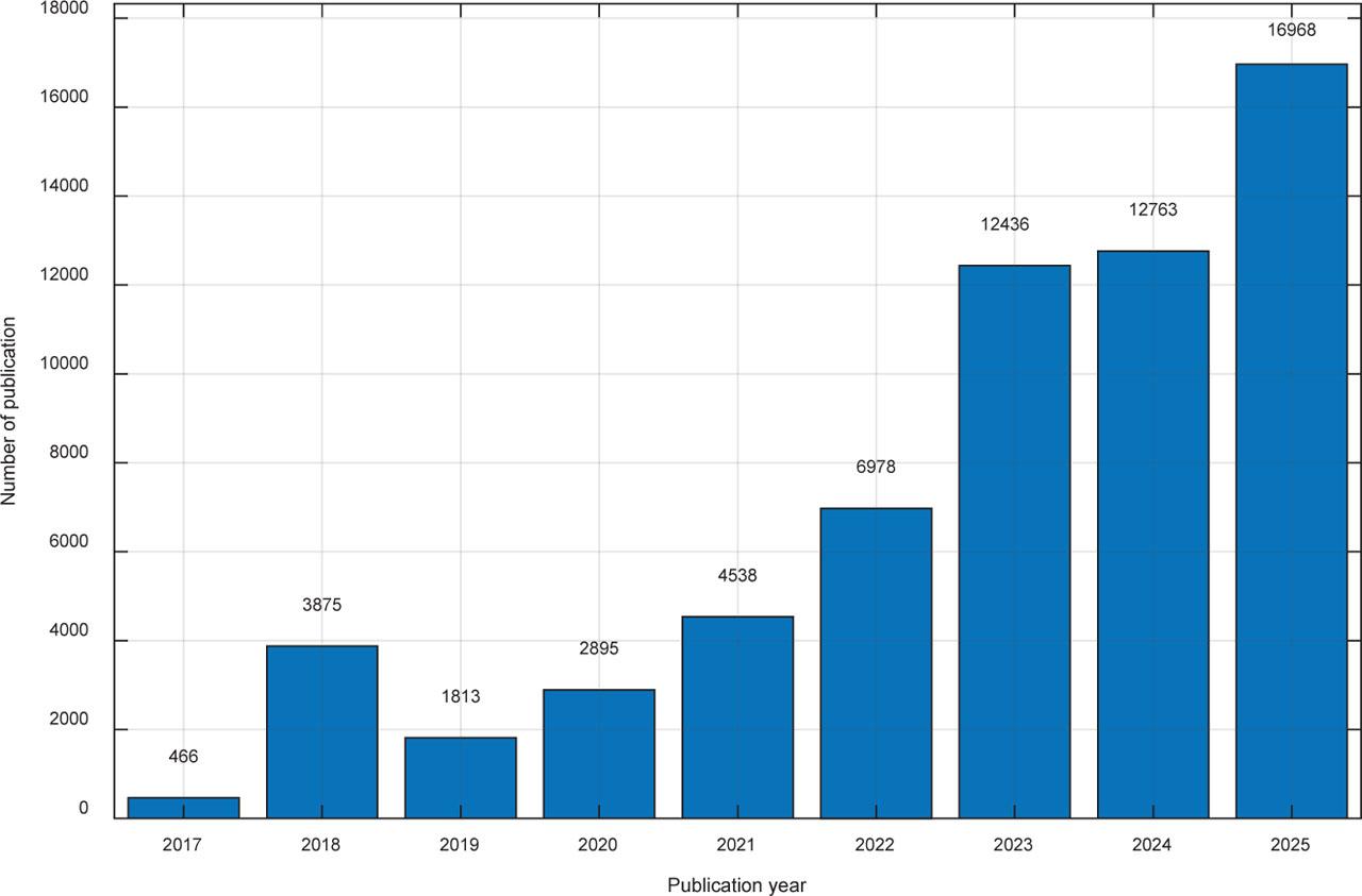
Annual number of publications on DT technology from 2017 to 2025. DT, digital twin.
The contributions of this work are as follows:
- (i)
it provides an electric-drive-specific interpretation of the terms digital model, digital shadow DT, using operational criteria based on physical-to-virtual data flow, online model updating synchronisation assessment;
- (ii)
it presents a critical analysis of existing DT-related studies in ED by comparing their strengths and limitations rather than only describing their applications;
- (iii)
it proposes a six-layer framework for electric-drive DT development that explicitly separates offline commissioning and model calibration from online synchronisation;
- (iv)
it demonstrates the practical use of the framework through an inverter-fed induction motor drive case, where data acquisition (DAQ)-based voltage, current speed measurements are combined with extended Kalman filter (EKF) state estimation to illustrate how the virtual model, represented by a fifth-order induction motor model in the stationary reference frame, can be synchronised with the physical drive.
Therefore, the novelty of the paper lies not in introducing another general DT architecture, but in translating DT concepts into practical and assessable criteria for electric drive systems, where the distinction between modelling, monitoring, synchronisation complete DT functionality is often unclear in the existing literature.
The rest of the paper is organised as follows. In the second section, we present the basic concepts of DT along with its advantages and level of integration. Moreover, an introduction to the characteristics of DT is provided in this section. Section 3 investigates the application of DT in ED, focusing on condition monitoring, scenario simulation RUL prediction. Section 4 introduces the proposed DT framework for electric drive systems, including its layered architecture, synchronisation formulation, model updating approach induction motor drive use case. Section 5 presents the discussion the final section summarises the main conclusions of the study.
The first pioneering principles for twinning systems lie in NASA’s training and simulation facilities during the Apollo 13 mission in 1970. These facilities were essential for mirroring the condition of the seriously damaged spacecraft and testing safe return operations. The concept of DT as a virtual representation of physical objects was formalised in 2002 by Michael Grieves. Further, it was named by NASA engineer John Vickers Lehmann et al. (2023), its definition changed and extended through the years (Chen, 2017; Gabor et al., 2016; Kannan and Arunachalam, 2019; Liu et al., 2025; Madni et al., 2019; Singh et al., 2021; Vrabič et al., 2018; Xu et al., 2019; Zheng et al., 2019). In particular, (Singh et al., 2021) offers a definition that captures key DT aspects, including real-time data exchange and bidirectional mirroring between the physical and digital counterparts.
In this paper, the term DT is used for systems that satisfy two requirements: (i) the virtual entity is synchronised with the physical drive using operational measurements; and (ii) the virtual entity supports a virtual-to-physical action, such as supervisory decision. A system that does not satisfy this first condition is classified as a digital model, whereas a system that satisfies it but does not include the second is classified as a digital shadow. These integration levels are explained in detail in Section 2.2.
Grieves and Vickers (2017) extended the formulation to include the entire product lifecycle introducing four new elements: (i) DT prototype (DTP), which refers to the virtual description of a prototype product, necessary to build the physical twin; (ii) DT instance (DTI), which refers to a specific instance of a physical product with which a particular DT remains connected throughout the product’s entire lifecycle; (iii) DT aggregate (DTA), which refers to a model combining individual DT instances into a comprehensive system; and DT environment (DTE), which refers to the entire digital platform on which the DT operates.
Recently, the DT has emerged as a powerful component of Industry 4.0 due to its advantages. Virtual models within a DT framework can support multi-scenario analysis with reduced need for physical prototyping. Consequently, the time needed for the design and analysis cycles is reduced most importantly, it reduces the cost for physical testing and validation (Singh et al., 2021). Moreover, the DT implementation improves the scheduling maintenance, since it can predict maintenance through real-time sensor data. On the other hand, it supports the ‘what- if’ analyses for risk assessment and system response evaluation. Furthermore, the DT allows real-time remote monitoring and control through the IoT devices, while increasing safety by not exposing people to dangerous environments. Additionally, DTs offers a safe training environment for operators for various processes from machinery operations to emergency scenarios. Finally, DT technology improves documentation and communication by providing stakeholders with accurate and updated information through real-time data and automated reporting.
The DT characteristics and structural elements can be categorised into three main groups: (i) key concepts of a DT, which define the way it is composed and operates; (ii) characteristics of a DT, which refer to the performance of the DT; and (iii) supporting components, which allow human interaction and visualisation.
The first category comprised physical objects, physical environment, virtual entity, virtual environment, physical-to-virtual connection twinning. The physical object exists in the real world it may be a vehicle, an electric drive, or even a factory, which operates in a physical environment, defined by the conditions and assets that affect it. On the other hand, the virtual entity imitates the physical object through 3D or behavioural models within a virtual environment for simulation, analysis optimisation. The monitoring and control of bidirectional data exchange between physical and virtual entities is defined by a physical-virtual connection. Moreover, twinning ensures continuous synchronisation between the virtual and physical entities.
Fidelity, state, parameters, control systems, self-evolving capability, multiscale, multiphysics multidisciplinary nature are included in the second category. The DT fidelity refers to the accuracy of the virtual model in representing the physical entity. Moreover, the DT states refer to the current conditions of the physical and virtual entities, while parameters are their measurable variables. Control systems enable the DT to implement changes in the physical assets. The DT model is multiscale, multiphysics multidisciplinary as it enables representations across multiple scales, multiple physical domains integrates models from multiple disciplines. Lastly, the self-evolving capabilities refer to the real-time adaptations, optimisation diagnosis.
Physical and virtual processes, the user interface hierarchical structure are reported in the last category. Physical processes represent the real behaviour of the physical entity, while the virtual processes on the other hand replicate its dynamics. Moreover, the DT provides a user interface for interaction and visualisation. Lastly, the component-level DTs are structured hierarchically to form larger, product-level DTs.
The level of integration between physical and virtual entities distinguishes the three different stages of DT representation, namely the digital model, the digital shadow the DT. These integration levels are summarised in the following paragraphs, presented according to a hierarchy based on the data exchange flow between physical and virtual entities.
In this paper, the distinction between a digital model, a digital shadow a DT is defined using operational criteria rather than only descriptive terminology. Four criteria are considered:
- (i)
the existence of a physical-to-virtual data flow,
- (ii)
the ability of the virtual model to be updated using measured data,
- (iii)
the evaluation of synchronisation between the physical and virtual systems through residuals or performance indicators, and
- (iv)
the presence of a virtual-to-physical decision path.
Accordingly, a digital model is an offline representation of the electric drive, without automatic updating from measured data (Fuller et al., 2020; Segovia and Garcia-Alfaro, 2022; Singh et al., 2021). A digital shadow receives measured data from the physical system and updates or corrects the virtual representation, but it does not automatically influence the physical drive (Fuller et al., 2020; Segovia and Garcia-Alfaro, 2022; Singh et al., 2021). A DT requires bidirectional integration, where the synchronised virtual model supports decisions that can affect the physical system through control, supervision, maintenance planning, or set-point adaptation (Fuller et al., 2020; Segovia and Garcia-Alfaro, 2022; Singh et al., 2021).
Figure 3 illustrates the three levels of integration of DT and their characteristics in terms of data exchanges between physical entities and their corresponding virtual ones and vice versa.
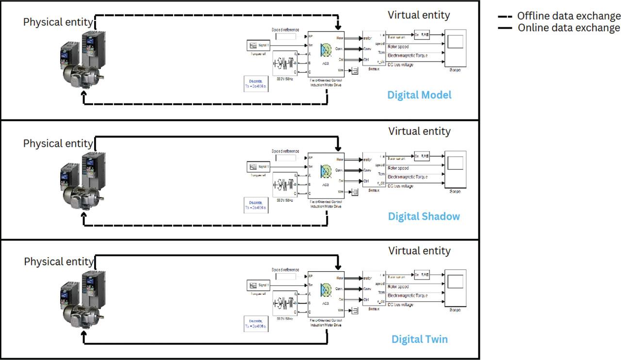
Digital model, digital shadow DT integration levels. DT, digital twin.
Table 1 summarises the criteria used in this review to classify these integration levels, with particular emphasis on their interpretation in electric-drive applications.
Criteria used to classify digital model, digital shadow DT integration levels in electric drive applications.
| Criterion | Digital model | Digital shadow | DT |
|---|---|---|---|
| Physical-to-virtual data flow | No automatic physical-to-virtual flow | Yes | Yes |
| Online model update | No | Yes | Yes |
| Synchronisation assessment | No or offline only | Yes | Yes |
| Virtual-to-physical decision path | No | No | Yes |
| Typical ED example | Offline Simulink/FEM model | EKF-based monitoring or fault diagnosis | Synchronised model with supervisory action or maintenance decision |
DT, digital twin; ED, electric drives; EKF, extended Kalman filter.
In the remainder of this review, we apply these integration levels to categorise the literature and to prevent mislabelling traditional modelling or estimation methods as DT implementations.
The modelling approach adopted in DT studies for ED depends strongly on the target function, such as scenario simulation, condition monitoring, or RUL prediction. To ensure consistent terminology, we reviewed the literature using the integration levels defined in Section 2.2.
Condition monitoring studies in ED are mainly concentrated at the level of model-based monitoring and diagnosis. The main strength is the integration of measured signals to enhance the consistency between the physical system and its virtual representation. However, most works stop at fault indication or model updating and do not report how the output of the virtual model is converted into a validated operational decision, such as an automatic setpoint adjustment, control action, maintenance command, or other virtual-to-physical feedback. This is why several works are classified as digital shadows rather than full DTs in the stricter terminology used here.
Additionally, experimental studies were conducted on the quantification and localisation of rotor unbalance faults using a reference model for fault diagnosis of rotating machinery (Wang et al., 2019). A digital shadow of a rotor system based on rotor dynamics was developed, where critical speed and unbalance response of the rotor under different conditions are obtained by finite element analysis, whereas fault conditions are simulated by incorporating screw holes into the rotating discs. Since the initial model showed discrepancies from measured vibration signals, the unbalanced mass parameter was updated using characteristic variables such as critical speed and unbalance response. Results show that the model updating technique can be used to construct a digital shadow that tracks the actual physical system.
Condition monitoring of an electric drive consisting of two induction motors facing each other and coupled by a drivetrain is performed in Cherifi et al. (2022). The researchers report that the simulation’s results were compared with the real ones taken from measurement the highest relative error was 5%. This result indicates that the digital shadow identifies the fault if a significant deviation from normal operation is detected.
Furthermore, Brandtstaedter et al. (2018) investigated the use of digital shadows for unbalance localisation and rotor temperature prediction in large drive trains. For unbalance localisation, a reduced-order rotor model was validated using bearing sensor data and frequency-based identification. The unbalance was represented as an external force, with its position, direction magnitude estimated by the algorithm. For temperature prediction, a 3D finite-element-based model of a synchronous motor rotor was continuously updated using speed, current stator-winding sensor data. The results showed that digital shadows can support fault localisation and indirect temperature estimation, helping operators improve cooling and start-up procedures.
Additionally, in Ebadpour et al. (2023), the internal states (the stator current components, rotor flux components, rotor speed load torque) of an induction motor drive were estimated using EKF observer along with sensorless field-oriented control, where the EKF acts as a synchronisation module between measured drive signals and the virtual induction motor model.
Moreover, Bouzid et al. (2020) developed a digital shadow for a wound rotor induction machine using a combination of finite element with coupled circuits (CFE-CC) approach. The method uses precomputed inductance functions to reduce computation time while preserving finite-element accuracy. It accounts for space harmonics, magnetic imbalance, rotor faults internal electromagnetic quantities such as bar currents and flux distributions. When coupled with thermal modelling, it can also estimate power-loss distribution and local temperature variations, supporting real-time monitoring and fault diagnosis.
Researchers in Adamou and Alaoui (2024) proposed an innovative approach that utilises an efficiency model-based digital shadow system for in situ failure detection and diagnosis of induction motors to ensure the reliability and continuous functionality of induction motors in industry. When validated on a case study on broken rotor bars using data from five motors, the proposed model achieved 99.99% precision in identifying one to four defective rotor bars and showed superior performance compared to vibration-based Fault Detection and Diagnosis (FDD) approaches.
Lastly, an application of the digital shadow for detecting stator inter-turn short circuit faults in AC motors is introduced in Rjabtsikov et al. (2021). Real-time data, integrated with a spatial model developed in Unity 3D, was coupled with the Linux robot operating system (ROS) to simulate motor behaviour under unbalanced stator currents and to notify users of potential fault occurrences and their progression.
Scenario simulation studies are valuable because they allow faults to be generated without damaging the physical drive. Their main limitation is that they can be mistaken for DT implementations even when they are not connected to the physical asset during operation. In the proposed terminology, such models become part of a DT only after their parameters and states are updated from measured operational data, and their outputs support a clearly specified decision process.
Zayed et al. (2023) proposed an Artificial Intelligence AI-based fault diagnosis framework for industrial DT systems using hybrid optimisation and machine-learning models. Simulated data were generated from updated DT models of a triplex pump and transmission system under several fault conditions, including leaks, blockages, bearing faults, shaft wear, gear faults sensor drift. Feature selection was then performed using optimisation algorithms, such as flower pollination algorithm (FPA), Particle Swarm Optimisation (PSO), Harris Hawks Optimisation (HHO), Jaya Algorithm (JA), Grey Wolf Optimiser (GWO), Salp Swarm Algorithm (SSA), followed by multi-class fault classification using k-Nearest Neighbours (KNN), decision tree random forest models. The study reports that the combination of the FPA algorithm with DT and FPA with Random Forest (RF) algorithm produces the highest fault detection accuracy, reaching 96.8% and 85.6%, respectively. Figure 4 illustrates the Hybrid optimisation and machine learning framework for fault diagnosis.
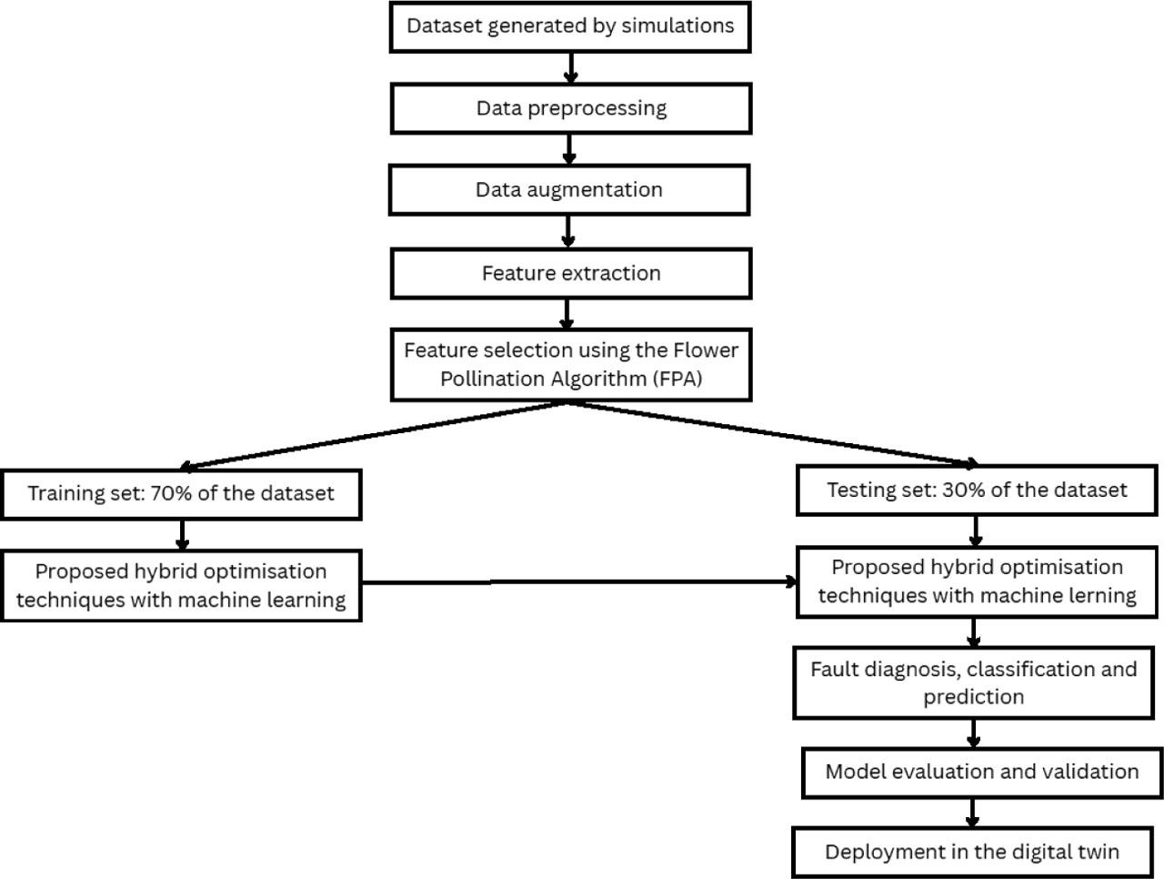
Hybrid optimisation and machine learning framework for fault diagnosis. DT, digital twin; FPA, flower pollination algorithm.
Furthermore, Xia et al. (2021) proposed a high-fidelity DT and deep transfer-learning framework for intelligent fault diagnosis in a triplex pump. A MATLAB-based DT model was continuously updated with real-time data and used to simulate fault conditions such as cylinder leakage, inlet blockage increased bearing friction. The results showed effective fault diagnosis with a small amount of experimental data, outperforming other data-driven methods.
Additionally, Gonzalez et al. (2020) proposed an open-loop high-fidelity Modelica model for a vertical transportation system to analyse and predict system behaviour. Simulated and measured variables, including cable tension, current, acceleration friction, showed good agreement in magnitude, but vibration amplitudes were less accurate due to unmodelled factors such as controller settings, guide-rail properties, input noise guiding-system vibrations. The model was therefore considered suitable for energy-efficiency analysis, but less reliable for comfort evaluation. Additional simulations showed that improved lubrication could have a stronger and more cost-effective impact on system performance than rail-alignment correction.
Lastly, Lopes et al. (2021) developed a 3D Finite Element Method (FEM) model of a three-phase induction motor under healthy and broken-rotor-bar conditions. Time- and frequency-domain analysis of simulated current signals showed increased amplitude at the broken-bar fault frequency, especially in the left sideband of the fundamental frequency. These signals were then used to train a multilayer perceptron neural network for fault classification. The study shows that 3D FEM models can generate useful fault-related quantities, such as current, torque, speed, electromagnetic field flux, supporting intelligent fault diagnosis when experimental fault data are costly or difficult to obtain.
RUL prediction extends research in ED towards maintenance applications. These methods estimate how long a component or system can continue operating before failure or degradation occurs. Existing RUL approaches are commonly grouped into physics-based, statistical, data-driven hybrid methods. Physics-based methods are interpretable because they rely on failure mechanisms, but they can be difficult to parameterise for complex drives. Data-driven methods can identify non-linear degradation trends, but they require representative data and careful validation under different operating conditions. Hybrid methods are therefore promising, provided that the model-updating procedure and the uncertainty of the health estimate are clearly reported.
Sivalingam et al. (2018) presented a physics-based digital model for RUL prediction of offshore wind turbine power converters. The approach combines failure mechanisms, operational data physical laws, with Failure Mode and Effects Analysis (FMEA) used to identify critical failure modes affecting performance and maintenance cost. Supervisory Control and Data Acquisition (SCADA) data were used to define the wind turbine operating profile, while a FAST turbine model generated torque and speed inputs for the generator model. Power losses were then estimated and used in a thermal model to calculate junction temperature. After validation, the analytical generator model was considered suitable for condition assessment and RUL prediction.
Furthermore, (Aivaliotis et al., 2019) proposed a methodology for calculating the RUL of ED systems using physics-based digital shadow models, where virtual models are synchronised with real-time operation by integrating data from ED controllers and sensors. This approach enables the monitoring and prediction of ED system conditions. Moreover, statistical-based models use historical data to fit random coefficient or stochastic process models for RUL prediction.
Lei et al. (2016) proposed a stochastic-process-based method for predicting the RUL of electric-drive systems. The method accounts for degradation uncertainty and uses a Kalman particle filter to estimate system states and predict RUL. Its effectiveness was demonstrated through simulations and accelerated bearing tests, showing high prediction accuracy.
The growing capabilities of Cloud Computing and Big Data have significantly increased their adoption in research. Within this context, researchers in Magadán et al. (2023) proposed a robust health prognostics method to predict the RUL of electric motor bearings under varying conditions without requiring model retraining or fine-tuning. The approach integrates frequency-domain signal analysis with a stacked autoencoder and a bidirectional Long Short-Term Memory (LSTM) neural network. The model is trained using the Intelligent Maintenance Systems (IMS) bearing dataset, evaluated on another IMS dataset further validated with the FEMTO and XJTU-SY bearing datasets, achieving high prediction accuracy.
Furthermore, a digital shadow for an Electrical Vehicles (EV) permanent magnet (PM) synchronous motor using an artificial neural network (ANN) and fuzzy logic was developed to compute the RUL of PM (Venkatesan et al., 2019). Simulation outcomes suggest that the developed digital shadow effectively estimates the RUL of the PM of the synchronous motor.
Lastly, Bejaoui et al. (2021) proposed a hybrid physics-based and data-driven prognostic method for estimating the RUL of squirrel-cage induction motors with broken rotor bars. A MATLAB/Simulink model was used to generate healthy and faulty datasets, from which torque, stator current speed were extracted as degradation-sensitive quantities. Principal component analysis was then applied to construct health indicators, which were used as inputs to an exponential degradation model for RUL estimation. The results showed that the method can accurately estimate RUL after fault degradation is detected. Figure 5 presents the flowchart of the prognosis algorithm for RUL prediction.
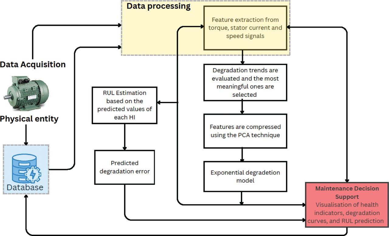
Flowchart of the prognosis algorithm for RUL prediction RUL, remaining useful life.
Table 2 emphasises strengths and limitations of the reviewed papers, showing that most existing works provide valuable DT building blocks, but often remain limited by insufficient online synchronisation, validation, or virtual-to-physical feedback.
Classification of DT studies in ED: Strengths and limitations.
| Group | References | Common strength | Common limitation |
|---|---|---|---|
| Online monitoring and digital shadow studies | Wang et al. (2019); Cherifi et al. (2022); Brandtstaedter et al. (2018); Ebadpour et al. (2023); Bouzid et al. (2020); Rjabtsikov et al. (2021) | Use online measurements, model updating, observers, reduced-order models, or physics-based simulation to monitor the physical system and improve consistency between measured and simulated behaviour. | Mainly support monitoring, state estimation, fault notification, or operator decision-making. Autonomous virtual-to-physical feedback is generally not demonstrated. |
| Fault diagnosis and classification studies | Adamou and Alaoui (2024); Zayed et al. (2023); Xia et al. (2021); Lopes et al. (2021) | Provide fault-diagnosis approaches using efficiency indicators, FEM-based data generation, hybrid physics-based/data-driven models, optimisation methods machine-learning classifiers. | Focused mainly on fault detection or classification. Corrective action, supervisory control, or closed-loop feedback to the physical drive is not reported. |
| Offline simulation and digital model studies | Gonzalez et al. (2020); Lopes et al. (2021); Bejaoui et al. (2021); Magadán et al. (2023) | Use high-fidelity models, FEM simulations, Simulink-generated datasets, or data-driven models to analyse system behaviour, generate fault data, or support prognostic modelling. | Mostly offline or open-loop approaches. Online synchronisation with the physical system and automatic model updating are limited or absent. |
| RUL prediction and prognostic studies | Sivalingam et al. (2018); Aivaliotis et al. (2019); Lei et al. (2016); Magadán et al. (2023); Venkatesan et al. (2019); Bejaoui et al. (2021) | Estimate degradation, health indicators, damage evolution, or RUL using physics-based, stochastic, ANN/fuzzy-logic, or deep-learning-based prognostic models. | Mainly focused on prediction and health assessment. The prognostic output is generally not connected to operational feedback, control action, or maintenance decision execution. |
| Framework and methodology-oriented studies | Sivalingam et al. (2018); Cherifi et al. (2022); Zayed et al. (2023) | Provide methodological elements for DT development, including DT frameworks, hierarchical modelling, hybrid simulation data-driven diagnostic pipelines. | Full DT implementation remains incomplete because online synchronisation, multiphysics integration, validation, or virtual-to-physical decision paths are not fully demonstrated. |
ANN, artificial neural network; DT, digital twin; ED, electric drives; RUL, remaining useful life.
Figure 6 presents the proposed DT architecture for ED as a layered, implementable framework consistent with the integration levels defined in Section 2.2. The architecture differs from generic DT diagrams in three electric drive aspects. First, it separates the offline stage from the online stage. In the offline stage, the machine model, inverter model, load model sensor scaling are calibrated. In the online stage, measured variables, such as voltage, current, speed, temperature, or vibration, are used to update the virtual entity. Second, the acquisition and signal-conditioning layer is considered an essential component of the DT, since measurements in electric-drive systems are often affected by Pulse Width Modulation (PWM) switching, scaling effects of isolation amplifiers, sensor noise, and synchronisation errors. Third, the architecture connects application services with practical actions at the electric drive system level, such as maintenance recommendations, supervisory setpoint adjustments, low-speed torque compensation adjustment, power reduction under overheating conditions, or alarm generation.

Proposed DT framework for electric drive systems. DAQ, data acquisition; DT, digital twin; PLCs, programmable logic controllers.
Therefore, the proposed architecture is not only a layered representation of DT components. It also serves as a practical checklist for determining whether an electric drive implementation should be classified as an offline digital model, an online digital shadow, or a complete DT with a validated feedback path.
Physical system layer represents the real electric-drive system, including the main hardware components and the sensors used to monitor its operation. The hardware includes the power converter, electrical machine, mechanical transmission load, while the measurement devices collect electrical, mechanical thermal variables from these subsystems. Typical measured variables include (i) voltages, generally obtained through voltage dividers or voltage transducers; (ii) currents, measured using shunt resistors, hall-effect sensors, or current transformers; (iii) rotational speed and position, derived from encoders, resolvers, or tachometers; (iv)torque, measured by torque sensors or transducers; (v) vibration, captured using accelerometers; and (vi) temperature, monitored through resistance temperature detectors or thermistors. In applications requiring galvanic isolation and signal adaptation, isolated amplifiers may be employed at the sensor interface to improve safety and measurement reliability.
Acquisition and communication layer forms the interface between the physical system layer and the upper digital layers. Its main role is to collect the signals generated by the measurement elements, convert them into usable digital data ensure their transmission to the data processing and virtual model layers. This layer typically includes acquisition hardware such as DAQ devices, programmable logic controllers (PLCs) SCADA gateways, together with communication protocols such as OPC UA, Modbus MQTT. Through these components, the layer enables the transfer of electrical, mechanical thermal measurements from the physical entity to the digital environment in a structured and timely manner, thereby supporting both offline analysis and online synchronisation.
Data processing layer is responsible for transforming the acquired raw measurements into reliable and structured data for modelling for the upper virtual model layer. It performs the processing required to ensure that signals from the acquisition and communication layer are consistent, synchronised suitable for subsequent modelling tasks. As shown in the proposed architecture, this layer contains three main functions: (i) data preparation, including scaling and resampling; (ii) time alignment, including signal synchronisation; and (iii) signal cleaning, including filtering and denoising. Through these operations, the layer improves data quality, removes noise ensures that electrical, mechanical thermal measurements can be meaningfully integrated into physics-based, data-driven, or hybrid models.
The virtual model layer represents the digital representation of the electric drive system and provides the modelling core of the proposed architecture. Its role is to reproduce the behaviour of the physical system in the digital environment using mathematical, data-driven, or combined modelling approaches. As shown in the proposed framework, this layer includes three-model categories: (i) a physics-based model, describing the electrical, mechanical thermal subsystems using mathematical equations; (ii) a data-driven model, representing these subsystems through models learned from measured data; and (iii) a hybrid model, which integrates physics-based and data-driven approaches to exploit the advantages of both. Through these alternative modelling structures, the layer enables system representation at different levels of fidelity and serves as the basis for calibration and runtime adaptation in the upper layer.
Model calibration and runtime adaptation layer ensure consistency between the physical system and its virtual representation during both commissioning and operation. It includes (i) offline calibration, which covers parameter estimation and model validation (ii) online adaptation, which covers state and parameter estimation together with model updating during operation. In this layer, the dashed green arrow denotes the runtime synchronisation and model-update pathway. It indicates the physical-to-virtual pathway through which acquired and pre-processed measurements are used for online state estimation, parameter estimation model updating. Thus, the green dashed pathway represents the continuous physical-to-virtual data flow that keeps the virtual model synchronised with the current operating state of the real electric drive system.
Application layer represents the service level of the proposed architecture, where the calibrated and continuously synchronised, virtual model is used to support advanced functions related to the operation, monitoring maintenance of the electric-drive system. As shown in the framework, this layer includes decision support, predictive maintenance, performance analysis, fault detection what-if simulation. These functions translate the outputs of the virtual model into actionable information for fault diagnosis, prognosis, operational evaluation the analysis of alternative scenarios. In this layer, the dashed red arrow denotes the closed-loop feedback pathway from the application layer back to the physical system. It indicates that the results generated by the decision support service can be translated into actions or recommendations affecting the real system, such as maintenance interventions or supervisory setpoints. In this sense, the red dashed pathway represents the virtual-to-physical link required to move beyond monitoring and model updating towards a fully DT implementation.
Let uk, denote the measured or reconstructed inputs of the drive at sampling instant k, such as stator voltages, inverter commands, or frequency reference. Let yk denote measured outputs, such as stator currents, speed, temperature, vibration, or input power. This physical-to-virtual data flow is consistent with general DT architectures, where measurements from the physical system are processed and mapped to update the virtual representation (Thelen et al., 2022; Zheng et al., 2019). A general discrete-time virtual model can be written as:
The synchronisation between the physical drive and its virtual representation can be evaluated using the output residual:
To keep the formulation independent of a specific estimator, the state correction can be written in a general observer form as
The correction gain may be designed from a linearised output model. The measurement Jacobian is given by:
For example, in Kalman estimators, this Jacobian contributes to the computation of the correction gain. In deterministic observers, it may be used to analyse convergence or to design observer gains. Thus, the same synchronisation framework can support different observer structures depending on the available measurements, noise level, computational constraints robust requirements.
In addition to state correction, parameter adaptation can be formulated as a moving-window optimisation problem:
The choice of Nw should balance responsiveness and robustness. A short window allows faster parameter adaptation but may increase sensitivity to measurement noise and transient disturbances. A longer window improves noise averaging and parameter stability, but may delay adaptation when the operating condition changes.
The regularisation coefficient λ controls how strongly the updated parameters are constrained around the nominal values. A small λ allows larger parameter changes, but may lead to unrealistic drift when the data are noisy or poorly informative, whereas a large value of λ improves physical consistency and numerical stability, but may prevent the model from adapting to real parameter changes.
Moving window optimisation and regularised parameter estimation are commonlfy used in system identification and moving horizon estimation to update model parameters while maintaining stability and physical consistency (Alessandri et al., 2008; Rao et al., 2003). The first term in Eq. (8) minimises the mismatch between measured outputs and virtual-model predictions over the recent time window. The second term penalises excessive deviation from the nominal parameter vector and prevents unrealistic parameter drift. In this way, model updating is performed only when supported by measured drive behaviour, while the regularisation term keeps the parameter values physically meaningful.
To demonstrate the practical applicability of the proposed framework, the workflow was applied to an inverter-fed induction motor drive operating under V/f control. The physical layer consisted of a 130 W induction motor supplied by a 200 W variable-frequency drive. The motor shaft was mechanically connected to a belt-pulley transmission, which transferred the mechanical power to an automotive alternator. The alternator was connected to a battery and an adjustable rheostat in series, allowing different loading conditions to be imposed during the experiment.
The measured electrical variables were the line voltages and line currents of the induction motor. The line voltages were acquired through voltage dividers, while the line currents were measured using shunt resistors. Isolation amplifiers were included in the measurement chain to provide galvanic isolation before data acquisition. The mechanical variable was the rotor speed, obtained from an incremental encoder.
In the acquisition and communication layer, the analogue measurement channels were sampled using a data-acquisition device. The acquired voltage and current signals were converted into physical units using the corresponding scaling factors. The data-processing layer performed time alignment, signal scaling despiking of PWM-induced spikes. These steps provided the processed voltage, current speed signals required for model calibration, synchronisation validation.
During the offline commissioning stage, the induction motor model was calibrated to obtain a physically consistent baseline before online operation. The electrical parameters were estimated from DC, locked-rotor no-load tests using least-squares phasor extraction, while the mechanical parameters were identified from coast-down experiments using non-linear least-squares fitting. The calibrated model was then validated by comparing simulated and measured current and speed responses. This validation step demonstrates the first stage of the framework, where the virtual model is adjusted until it can reproduce the main behaviour of the physical drive.
The virtual-model layer was implemented using a fifth-order induction motor model expressed in the stationary α-β reference frame. For online synchronisation, an EKF was used with the following state vector:
At the application layer, the synchronised model was used as a basis for decision support. For example, when the V/f drive includes a torque-boost parameter, the DT can compare candidate parameter values using measured and estimated quantities such as rotor flux magnitude, current magnitude, speed input power. The selected operating condition should reduce power consumption while maintaining acceptable flux, current speed. In this way, the use case demonstrates the complete pathway from measurement acquisition, signal processing, offline calibration, online synchronisation, residual evaluation decision-support generation.
Table 3 presents the demonstrative elements of the induction motor DT use case.
Demonstrative elements of the IM DT case study.
| Framework element | Implementation in the use case |
|---|---|
| Physical system | Induction motor drive supplied by a Mitsubishi FR-D720S-014SC-EC inverter, with belt-pulley transmission, automotive alternator battery–rheostat adjustable load. |
| Measurement layer | Line voltages, line currents rotor speed were acquired using voltage dividers composed of 2.2 MΩ and 1 kΩ resistors, 0.1 Ω, 3 W, ±1% shunt resistors, TI AMC1300 isolation amplifiers an incremental encoder with a resolution of 1,000 pulses/rev. |
| DAQ and communication | The analogue voltage and current signals were sampled using an NI PCI-6251 DAQ card in combination with an NI BNC-2120 connector block, while the rotor speed was measured from the incremental encoder pulses through counter input ctr0, connected to PFI8 of the DAQ system. |
| Data processing | Time alignment, signal scaling despiking of PWM-induced spikes. |
| Offline commissioning | Electrical parameters estimated from DC, locked-rotor no-load tests; mechanical parameters estimated from coast-down tests. |
| Virtual model | Fifth-order induction motor model expressed in the stationary α -β reference frame |
| Online synchronisation | EKF-based correction of current, flux, speed load-torque states using measured signals. |
| Synchronisation assessment | Residual comparison between measured and estimated current and speed responses. |
| Application layer | Decision support for torque-boost selection based on flux magnitude, current magnitude, speed input power. |
DAQ, data acquisition; DT, digital twin; EKF, extended Kalman filter.
The review indicates that electric drive DT research is well developed in modelling, but the connection from virtual-model outputs to real operational actions is still insufficiently demonstrated. Many studies provide detailed physics-based models, finite-element models, observers, or machine-learning classifiers, but they do not always close the loop between the virtual output and the physical drive. As a result, they are valuable building blocks for DT development but should not automatically be classified as full DT implementations.
The proposed framework addresses this issue by defining three clear requirements. First, measured data must be used to update the virtual entity. Second, the synchronisation accuracy between the physical drive and the virtual model must be evaluated. Third, the application layer must generate a decision or recommendation that can influence the operation of the drive. These requirements make the classification more consistent and help prevent conventional models or monitoring systems from being incorrectly labelled as full DTs.
For ED, the acquisition and data-processing layers are especially important. PWM switching, sensor bandwidth, scaling errors and DAQ synchronisation can affect the quality of the virtual model. Therefore, a DT for ED cannot be evaluated only by the fidelity of the model; it must also be evaluated by the quality of the measurement and the consistency of online synchronisation. The same framework can be extended to multi-drive or networked drive systems by applying physical-to-virtual synchronisation at the individual drive level and coordinating the synchronised models through a supervisory layer. In this case, scalability depends on synchronised data acquisition, communication latency, computational load the definition of system-level residuals that capture interactions among coupled drives.
The proposed use case illustrates how the framework can be implemented in practice. Offline tests are used to estimate parameters and validate the model. During online operation, measured data update the EKF virtual entity, while residuals are used to evaluate how closely the virtual model follows the physical drive. At the application layer, supervisory decision support compares possible operating actions, such as torque-boost adjustment, input power, flux, speed current constraints.
Practical adoption of the proposed framework has some limitations. Its accuracy depends on reliable sensors, DAQ resolution, correct scaling time synchronisation. In addition, online EKF synchronisation, residual evaluation parameter adaptation increase computational load, especially for high sampling rates or multi-drive systems. Finally, reliable communication and well-defined decision thresholds are needed to avoid incorrect supervisory recommendations.
Since the present paper is a review, the use case is presented as an implementation workflow rather than as a detailed experimental validation. A full experimental validation will be reported in a separate study. Here, the purpose is to show how offline calibration, online synchronisation, residual evaluation decision support can be organised within an electric drive DT framework.
Future work should focus on detailed experimental validation of the proposed framework under different operating conditions and fault scenarios. The validation should evaluate how parameter uncertainty affects the framework, whether the proposed control actions improve energy efficiency how accurately faults can be detected.