
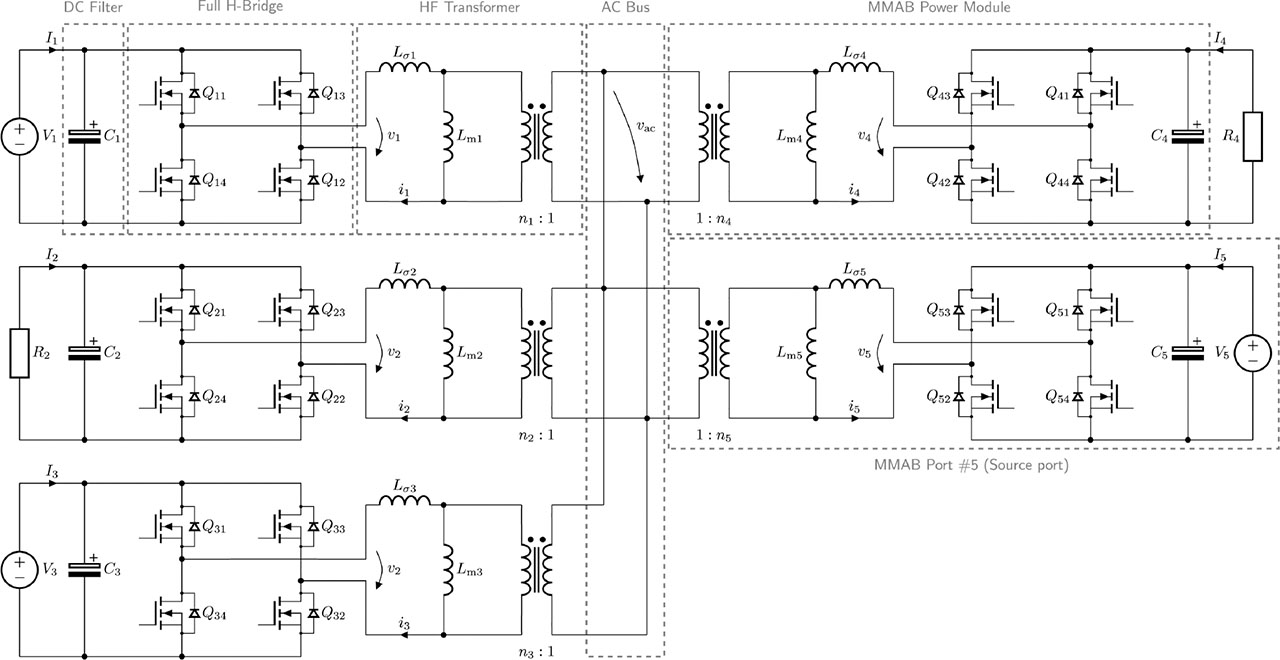
Figure 1.
MMAB converter topology. MMAB, modular multi-active bridge.
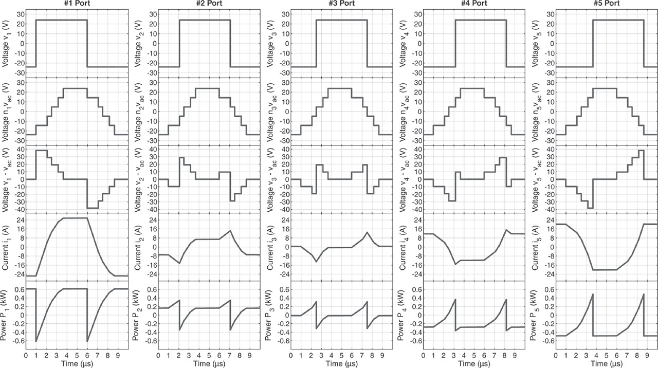
Figure 2.
Typical operating waveforms of the five-port MMAB converter. The waveforms are obtained with the following parameters: Vi = 24 V; Lσi = 1.4μH; Lmi = 600 μH; ni = 6 / 3; i ∈ {1,..., k}; ϕ1 = 0.149; ϕ2 = 0.039; ϕ3 = −0.003; ϕ4 = −0.068; ϕ5 = −0.118; P1 = 360 W; P2 = 120 W; P3 = 0 W; P4 = −180 W; P5 = −300 W. MMAB, modular multi-active bridge.

Figure 3.
Lossless equivalent circuit of MMAB converter. MMAB, modular multi-active bridge.
Table 1.
Single-core performance benchmarks of MabDec library.
| Number of ports | 2 | 3 | 4 | 5 | 6 | 7 | 8 |
|---|---|---|---|---|---|---|---|
| Decoupling time | 10.13 us | 21.24 us | 36.99 us | 59.58 us | 88.79 us | 123.63 us | 168.24 us |
| Function geninv() | 7.60 us | 16.84 us | 30.42 us | 50.19 us | 76.52 us | 108.63 us | 149.99 us |
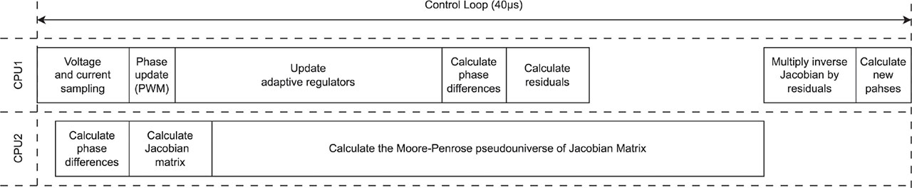
Figure 4.
Parallelisation of CPU1 and CPU2.
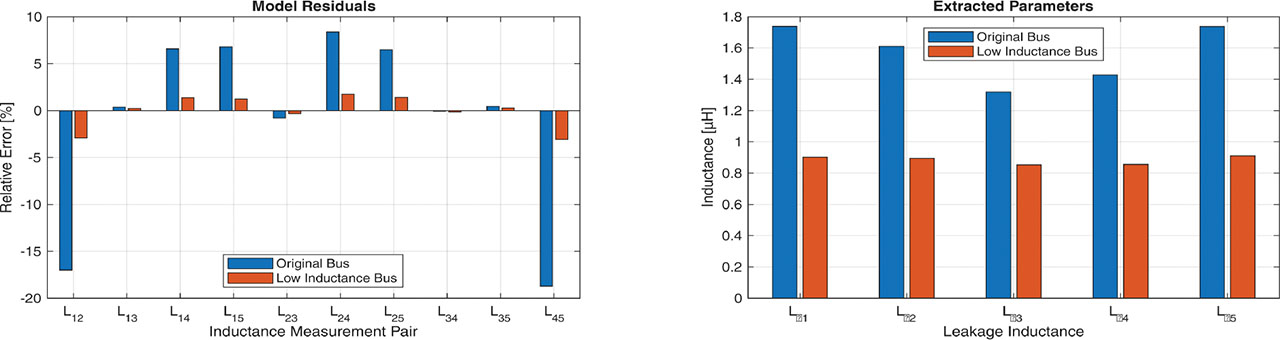
Figure 5.
Graphs of relative error of identification and identified inductance.
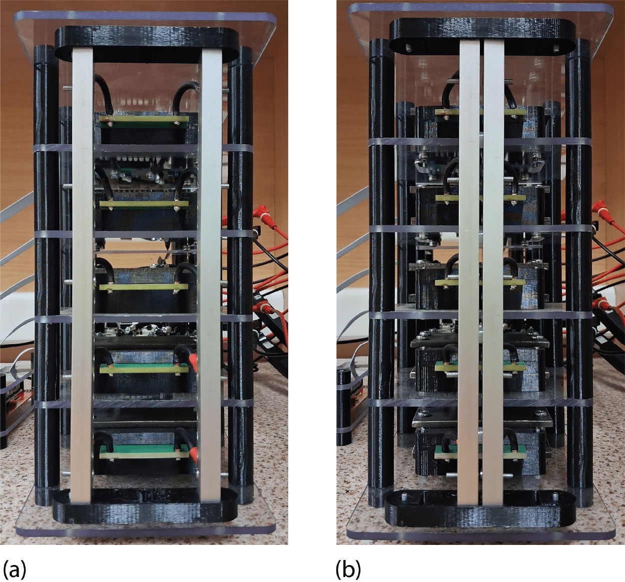
Figure 6.
AC Bus: (a) Original bus; (b) Low inductance bus.
Table 2.
MMAB converter nameplate parameters.
| Port #1 | Port #2 | Port #3 | Port #4 | Port #5 | Unit | |
|---|---|---|---|---|---|---|
| Maximum power | 360 | 360 | 360 | 360 | 360 | W |
| Maximum current | 15 | 15 | 15 | 15 | 15 | A |
| Nominal voltage | 24 | 24 | 24 | 24 | 24 | V |
| Leakage inductance | 0.902 | 0.893 | 0.853 | 0.856 | 0.911 | μH |
| Magnetising inductance | 600 | 600 | 600 | 350 | 350 | μH |
| Transformer ratio | 6:3 | 6:3 | 6:3 | 6:3 | 6:3 | - |
| Port capacitance | 880 | 880 | 880 | 880 | 880 | μF |
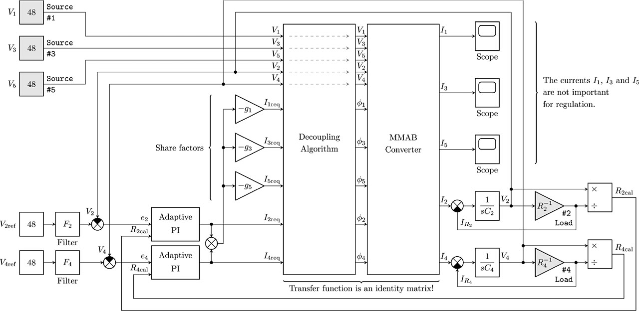
Figure 7.
Block diagram of control system. MMAB, modular multi-active bridge; PI, proportional integral.
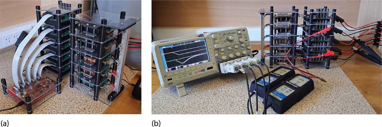
Figure 8.
Experimental prototype of the five-port MMAB converter: (a) detail of the DSP-based control board; (b) current and voltage sensing stage. MMAB, modular multi-active bridge. DSP, digital signal processor.
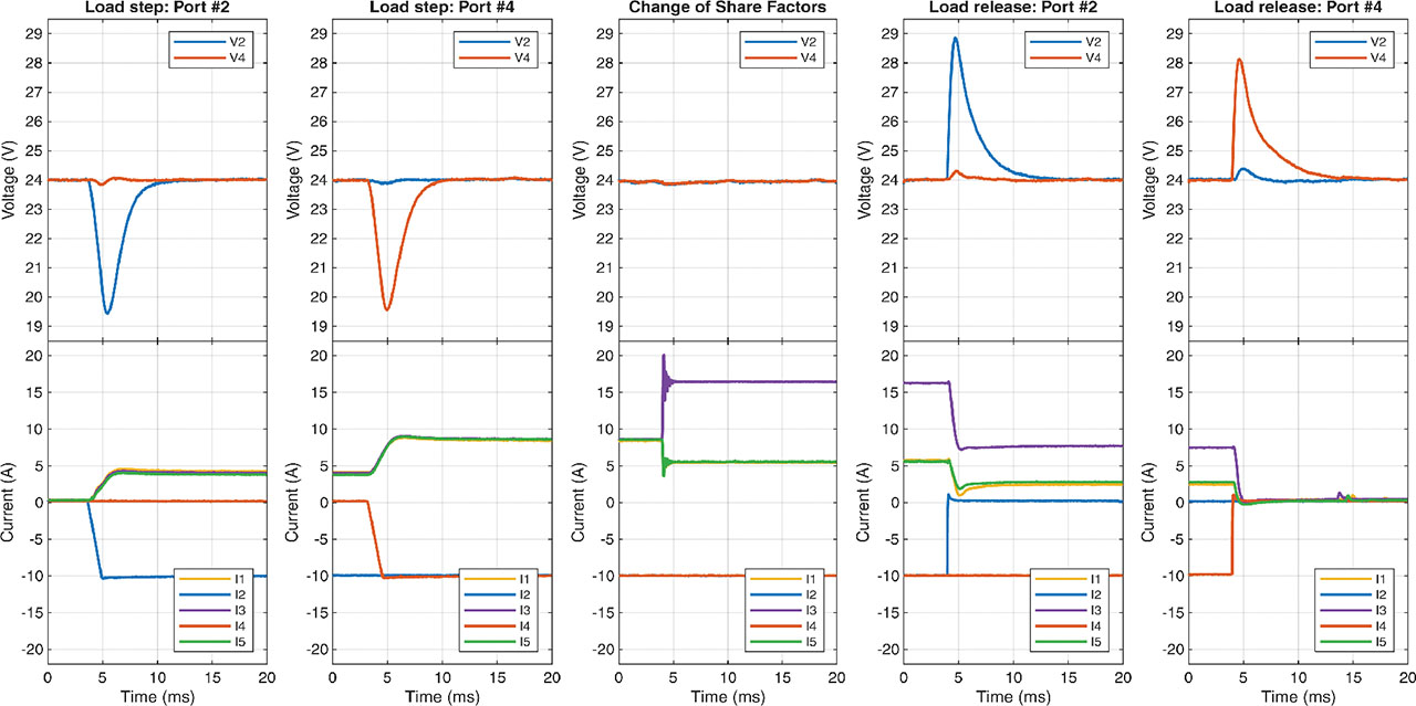
Fig. 9.
Experimental results: (left) load step; (centre) share factor change; (right) load release.